Table of Contents
Advertisement
Advertisement
Table of Contents

Subscribe to Our Youtube Channel
Related Manuals for Paradox Spectra 1759EX V1.0


Summary of Contents for Paradox Spectra 1759EX V1.0
- Page 1 1759EX V1.0 & I E F E R E N C E N S T A L L A T I O N A N U A L 1 7 5 9 E X...
-
Page 3: Table Of Contents
Bell on Communication Failure ............37 Configuring The LED Keypads ............12 Dial Tone Delay................37 Programming Using A Paradox Memory Key ........13 Maximum Dialing Attempts............... 37 Delay Between Dialing Attempts ............38 A C C E S S C O D E S ..........1 4 Alternate Dial Option ................ - Page 4 PC Password ..................45 PC Telephone Number ..............45 Call WinLoad Software ..............45 Answer WinLoad Software ............... 45 Auto Event Buffer Transmission ............46 Call Back WinLoad ................46 U S E R O P E R A T I O N ......... . 4 7 Trouble Display .................
-
Page 5: I N T R O D U C T I O N
P A R T 1 : I N T R O D U C T I O N 1 . 1 F E A T U R E S • Up to 15 fully programmable zones • Two completely independent partitions. Many of the features and options in the Spectra System can be independently set for each partition such as event reporting, entry/exit delay, auto-arming and many more. -
Page 6: Detectors, Keypads And Expansion Modules
D E T E C T O R S , K E Y P A D S A N D E X P A N S I O N M O D U L E S If you would like to obtain more information on our line of keypads, security system accessories or other security products, please contact your local Paradox distributor or visit our web site at http://www.paradox.ca. 1.3.1... - Page 7 1.3.10 IGITAL ETECTORS The Paradox Digigard (50/60/70) digital motion detectors can immediately identify the signal produced by a moving human body and will not be triggered by any other occurrences in the protected area.
-
Page 8: Installation
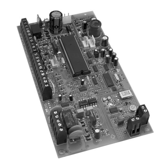
P A R T 2 : I N S T A L L A T I O N 2 . 1 L O C A T I O N A N D M O U N T I N G Before mounting the cabinet, push the five white nylon mounting studs into the back of the cabinet. - Page 9 Figure 2.2: Spectra 1759EX Control Panel Overview Refer to AC Power and Backup Battery Connections on page 6. Refer to Single Zone Inputs on To connect the 5A Alarm Relay and the PGMs, refer to Relay and PGM Connections on page 9. page 9 To connect AC power, refer to AC Power and Backup Battery Connections on page 6.
-
Page 10: Auxiliary Power Terminals
2 . 5 A U X I L I A R Y P O W E R T E R M I N A L S The auxiliary power supply terminals can be used to power motion detectors, keypads and other modules or accessories in the security system. -
Page 11: Single Zone Inputs
Figure 2.3: Relay and PGM Connections AUX+ or External Power Supply. See Programmable Output Connections on page 8 2 . 9 S I N G L E Z O N E I N P U T S Detection devices such as motion detectors and door contacts are connected to the control panel's zone input terminals. Figure 2.4 (below) demonstrates single zone input terminal connections recognized by Spectra. -
Page 12: Keyswitch Connections
Each keypad has one zone input terminal, allowing you to connect one motion detector or door contact directly to a keypad. The keypad can then communicate the status of the zone to the control panel. A maximum of two keypad zones can be used with each control panel. -
Page 13: Winload Software For Windows
Program the Spectra Series control panels remotely or on-site using the Winload Software for Windows®. For more information, contact your local Paradox Distributor or visit our web site at http://www.paradox.ca. If you are using the WinLoad software, you must program the features explained on pages 45 and 46. -
Page 14: Configuring The Led Keypads
Figure 3.1: Data Display Mode (LED Keypads Only) To access the Data Display Mode, press the [enter] key after entering a section and before entering any data. The three LEDs as indicated will begin to flash indicating that you are in the Data Display Mode. 1 6 8 6 H 1 6 8 6 V 1 6 8 9... -
Page 15: Programming Using A Paradox Memory Key
P R O G R A M M I N G U S I N G A P A R A D O X M E M O R Y K E Y Copy the sections of one Spectra control panel into the Paradox Memory Key (PMC-3). Then copy the contents of the Memory Key into as many Spectra control panels as needed. -
Page 16: A C C E S S C O D E
P A R T 4 : A C C E S S C O D E S The Spectra 1759EX control panel supports the following access codes: INSTALLER CODE: Used to program all control panel settings except User Access Codes. SYSTEM MASTER CODE (001) Provides full access. -
Page 17: Lock Master Code
4.4.2 ARTITION SSIGNMENT S e c t i o n s [ 3 0 2 ] t o [ 3 4 8 ] : U s e r C o d e s 0 0 2 t o 0 4 8 O p t i o n O F F = D e n y a c c e s s t o p a r t i t i o n 2 ( d e f a u l t ) [ 2 ]... -
Page 18: What Is An Expansion Input
P A R T 5 : Z O N E P R O G R A M M I N G The Spectra 1759EX control panel’s zone assignment depends on where the detection devices are connected (see Table 4). Table 4: Zone Recognition Table Device connected to 1759EX which input? -
Page 19: Reassign Zones To Expansion Inputs
5 . 3 R E A S S I G N Z O N E S T O E X P A N S I O N I N P U T S S e c t i o n [ 1 2 6 ] : G e n e r a l O p t i o n s O p t i o n [ 8 ] O F F = R e a s s i g n Z o n e s t o E x p a n s i o n I n p u t s D i s a b l e d ( d e f a u l t ) O p t i o n [ 8 ] O N = R e a s s i g n Z o n e s t o E x p a n s i o n I n p u t s E n a b l e d... -
Page 20: Zone Definitions
Figure 5.1: Spectra Zone Programming [001] = Zone 1 [009] = Zone 9 [002] = Zone 2 [010] = Zone 10 Press the [003] = Zone 3 [011] = Zone 11 ] key [004] = Zone 4 [012] = Zone 12 ENTER [005] = Zone 5 [013] = Zone 13... -
Page 21: Exclusive Zone Definitions
5.5.3 OLLOW ONES S e c t i o n s [ 0 0 1 ] t o [ 0 1 5 ] : Z o n e s 1 t o 1 5 , F i r s t D i g i t = When an armed Follow Zone opens, the control panel will immediately generate an alarm, unless an Entry Delay zone opens first: •... -
Page 22: Zone Partition Assignment
Figure 5.2: Bell Output During Fire Alarm Figure 5.3: Delayed 24Hr. Fire Zone 5 . 7 Z O N E P A R T I T I O N A S S I G N M E N T S e c t i o n s [ 0 0 1 ] t o [ 0 1 5 ] : Z o n e s 1 t o 1 5 The control panel provides the option of partitioning the security system into two completely independent systems. - Page 23 [4] OFF / [5] ON: Audible Pulsed Alarm When the conditions for an alarm have been met, the control panel can transmit the appropriate Zone Alarm report code (see page 33) and provides a pulsed output (see Figure 5-2 on page 20) for any bells or sirens connected to the control panel’s bell output.
-
Page 24: Zone Speed
5 . 9 Z O N E S P E E D S e c t i o n s [ 0 5 0 ] t o [ 0 6 4 ] : Z o n e s 1 t o 1 5 0 0 1 t o 2 5 5 X 1 0 m s , D e f a u l t = 6 0 0 m s The Zone Speed defines how quickly the control panel will respond to an open zone. -
Page 25: Viewing The Wireless Transmitter Signal Strength
6.1.2 ELETING SSIGNED IRELESS RANSMITTERS S e c t i o n s [ 6 0 1 ] t o [ 6 0 8 ] How Do I Delete Assigned Wireless Transmitters? Press the [ ] key. ENTER Enter your [ INSTALLER CODE Enter the desired [ ] (from sections [601] to [608]). -
Page 26: Supervision Options
On an LED Keypad: The serial number digits will appear one at a time by illuminating the corresponding LED light. To view the next digit, press the [ ] key. ENTER On an LCD Keypad: The first three digits of the serial number will appear. Press the [ ] key three times to view the ENTER next three digits. - Page 27 Spectra 1759EX to accept transmissions from an Omnia remote control only. Enabling option [8] configures the Spectra 1759EX to accept transmissions from a Parakey remote control only. 6.5.2 1759EX SSIGNING A EMOTE ONTROL TO THE PECTRA S e c t i o n s [ 7 3 1 ] t o [ 7 3 8 ] : R e m o t e C o n t r o l s 1 t o 8 r e s p e c t i v e l y Remote controls are assigned to the module using the Automatic Learning method.
-
Page 28: Button Options
Table 7: Remote Control Button Programming Remote Control Button Programming (refer to Table 8) Section [711] ____/____/____/____/____/____/____/____ Remote Control # 1 A+B C+D A+C B+D [712] ____/____/____/____/____/____/____/____ Remote Control # 2 A+B C+D A+C B+D [713] ____/____/____/____/____/____/____/____ Remote Control # 3 A+B C+D A+C B+D [714] ____/____/____/____/____/____/____/____... -
Page 29: Switch To Stay Arming
P A R T 7 : A R M I N G A N D D I S A R M I N G O P T I O N S 7 . 1 S W I T C H T O S T A Y A R M I N G S e c t i o n [ 1 3 3 ] = P a r t i t i o n 1 , S e c t i o n [ 1 3 4 ] = P a r t i t i o n 2 O p t i o n O F F = S w i t c h t o S t a y A r m i n g D i s a b l e d ( d e f a u l t ) -
Page 30: No Movement Auto-Arming
7.6.1 IMER S e c t i o n [ 1 1 1 ] = P a r t i t i o n 1 , [ 1 1 2 ] = P a r t i t i o n 2 Select the section corresponding to the desired partition and program the time (use the 24-hour clock i.e. -
Page 31: Bell Squawk On Arm/Disarm With Keypad
7 . 1 1 B E L L S Q U A W K O N A R M / D I S A R M W I T H K E Y P A D S e c t i o n [ 1 3 0 ] : A r m i n g / D i s a r m i n g O p t i o n s O p t i o n O F F = B e l l S q u a w k o n A r m / D i s a r m D i s a b l e d ( d e f a u l t ) [ 7 ]... -
Page 32: Tamper Recognition
8 . 3 T A M P E R R E C O G N I T I O N S e c t i o n [ 1 3 2 ] : Z o n e O p t i o n s [1] OFF / [2] OFF: Tamper Recognition Disabled (default) If the system is armed or disarmed, the control panel will display the zone as open in the keypad display, but will not generate an alarm. -
Page 33: Panic Lockout Timer
Whether the system is partitioned or not, the control panel will report all panic alarms to partition 1. 8 . 5 P A N I C L O C K O U T T I M E R S e c t i o n [ 0 9 4 ] When a panic alarm is activated, the control panel can ignore the disarm signal from a remote control for a specified period. - Page 34 P A R T 9 : R E P O R T I N G A N D D I A L E R S E T T I N G S The following section explains all the features and options that must be programmed in order for your security system to properly report system events to a central station.
-
Page 35: Reporting/Dialer (Enable/Disable)
9 . 1 R E P O R T I N G / D I A L E R ( E N A B L E / D I S A B L E ) S e c t i o n [ 1 3 5 ] : D i a l e r O p t i o n s O p t i o n [ 3 ] O F F = R e p o r t i n g / D i a l e r D i s a b l e d ( d e f a u l t ) O p t i o n [ 3 ] O N = R e p o r t i n g / D i a l e r E n a b l e d... - Page 36 9.2.6 LARM ESTORE EPORT ODES S e c t i o n s [ 1 9 1 ] t o [ 1 9 4 ] A report code can be programmed for each of the 15 available zones. The control panel can transmit these report codes to the central station identifying which zone was restored.
-
Page 37: Central Station Telephone Numbers
9.2.11 YSTEM ROUBLE ESTORE ODES S e c t i o n s [ 2 0 8 ] t o [ 2 1 0 ] Whenever the system restores one of the troubles listed in section 9.2.10, the control panel can send the appropriate report code to the central station identifying the type of system trouble restore. -
Page 38: Pager Delay
Table 10: Reporting Formats Value Entered Reporting Format Ademco Slow (1400Hz, 1900Hz, 10BPS) Silent Knight Fast (1400Hz, 1900Hz, 10BPS) SESCOA (2300Hz, 1800Hz, 20BPS) Ademco Express (DTMF 4+2) 5 (Default) Ademco Contact ID Pager Format If Hexadecimals (0 to FF) are used to program the report codes, verify that the pager also supports Hexadecimals. -
Page 39: Event Call Direction
9 . 7 E V E N T C A L L D I R E C T I O N Section [137] Option [1] ON = Call Telephone #1 for Arm/Disarm Report Codes in sections [160] to [186] (page 33) Option [2] ON = Call Telephone #2 for Option [3] ON = Call Telephone #1 for Alarm/Restore Report Codes in sections [187] to [196] (pages 33 to 34) -
Page 40: Delay Between Dialing Attempts
9 . 1 3 D E L A Y B E T W E E N D I A L I N G A T T E M P T S S e c t i o n [ 0 8 2 ] 000 to 255 seconds, Default = 20 seconds This delay determines the amount of time the control panel will wait between each dialing attempt. -
Page 41: Pgm Activation Event
S e c t i o n [ 1 3 5 ] : D i a l e r O p t i o n s [1] OFF / [2] OFF: TLM Disabled [1] OFF / [2] ON: Trouble Only Upon line test failure, a TLM Trouble will appear in the keypads’... -
Page 42: Pgm Deactivation Event
1 0 . 2 P G M D E A C T I V A T I O N E V E N T S e c t i o n s [ 1 2 1 ] , [ 1 2 3 ] , [ 1 2 5 ] After PGM activation, the PGM will return to its normal state (deactivate) when the programmed PGM Deactivation Event occurs. -
Page 43: Hardware Reset
P A R T 1 1 : S Y S T E M S E T T I N G S 1 1 . 1 H A R D W A R E R E S E T Performing a hardware reset will set all control panel settings to factory default except for the Panel ID and PC Password. Also, the event buffer will not be erased. -
Page 44: Keypad Tamper Supervision
If Confidential Mode is enabled and no actions are performed on the keypads for the time defined by the Confidential Mode Timer, all the keypads’ LEDs will be off and LCD screens will show “Paradox Family” until either a key is pressed or an access code is entered. -
Page 45: Installer Quick Functions Keys
1 1 . 1 1 I N S T A L L E R Q U I C K F U N C T I O N S K E Y S After entering the Installer Code, you can press a key to perform specific actions as described below. 11.11.1 I NSTALLER ] + [... -
Page 46: Wireless Transmitter Low Battery Supervision
After removing an expansion bus module from the communication bus, the control panel keeps the module’s programmed sections in memory. Therefore, if you add or replace a module or when you have downloaded the contents of the Paradox Memory Key (see section 3.4), you can reprogram the modules with the settings saved in the control panel. To do so, enter section [750] and press [ ]. -
Page 47: Panel Answer Options
P A R T 1 2 : S E T T I N G S F O R W I N L O A D S O F T W A R E 1 2 . 1 P A N E L A N S W E R O P T I O N S The following two options define how the control panel answers an incoming call from a computer using the WinLoad Software for Windows®. -
Page 48: Auto Event Buffer Transmission
instructions on the ADP-1 adapter. When the computer has dialed, press [ ] followed by the Installer Code, then press the ENTER ] key to manually answer the WinLoad software from the control panel. FORCE 1 2 . 7 A U T O E V E N T B U F F E R T R A N S M I S S I O N S e c t i o n [ 1 3 6 ] : D i a l e r O p t i o n s O p t i o n O F F = A u t o E v e n t B u f f e r T r a n s m i s s i o n D i s a b l e d ( d e f a u l t ) -
Page 49: Trouble Display
P A R T 1 3 : U S E R O P E R A T I O N 1 3 . 1 T R O U B L E D I S P L A Y The Spectra system continuously monitors fourteen possible trouble conditions. When a trouble condition occurs, the [ ] key or ] indicator will illuminate on the LED keypads or “Trouble”... -
Page 50: Programming Access Codes
Table 12: Trouble List LED # Description Details Keypad Fault If the keypad is no longer communicating with the control panel, the [ ] or [ TRBL FORCE will flash, the [ ] key will illuminate (the LCD keypad displays “Keypad Fault”) FORCE or [16] and the keypad will emit four consecutive beeps at 5-second intervals. -
Page 51: Stay Arming
keypad will emit a Rejection Beep. When you have correctly armed the system, the appropriate indication will turn on and the Exit Delay will be initiated. Please note that Regular Arming can also be activated through Auto-Arming, Keyswitch Arming or One-Touch Arming. -
Page 52: One-Touch Arming
How do I Program Bypass Entries? Press the [ ] key. Key in a valid [ ACCESS CODE Select one or more [ ] you wish to bypass. ZONES Once you have entered the desired bypass entries, press the [ ] key to accept these entries. -
Page 53: Auto-Arming
1 3 . 1 2 A U T O - A R M I N G ( N O T T O B E U S E D W I T H U L I N S T A L L A T I O N S ) Each partition can be programmed to arm every day at the time specified by the Auto-Arm Timer or for the period specified by the No Movement Timer. - Page 54 FCC REGISTRATION NUMBER:5A7CAN-22633 - AL - E CAUTION: RINGER EQUIVALENCE NUMBER:0.1B (U.S. & CANADA) Changes or modifications not expressly approved by PARADOX USOC JACK: RJ31X (USA), CA31A (CANADA) SECURITY SYSTEMS could void the user's authority to operate equipment.
- Page 55 Technical support can also be reached by fax at (450) 491-2313, or via e-mail at support@paradox.ca. © 2002 Paradox Security Systems Ltd. Spectra, WinLoad, InTouch, ParaVox, Digital Vision and Digigard are trademarks of Paradox Security Systems Ltd. P E C T R A E R I E S...
- Page 56 I N D E X N u m e r i c s 24Hr. Buzzer Zone ............19 Call Back Feature ............46 24Hr. Delayed Fire Zone ..........19 Call Upload/Download Software ........43 24Hr. Standard Fire Zone ..........19 Call WinLoad Software ............
- Page 57 Follow Zones ..............19 No Exit Delay When Arming with Remote Control ..29 Force Arming ..............49 No Movement Auto-Arming ..........28 Force Zones ..............21 Number of Rings ............. 45 Global PGM ..............39 One-Touch Arming ............ 28 Ground ................
- Page 58 ........25 ..............15 Assigning to User Access Codes Stay Arming ............24 Assignment Mode User Operation ..............47 ..............25 Deleting ............... 24 Programming ......25 Programming Remote Control Buttons Winload Software ............11 Report Codes ..............33 Wireless Transmitters Reporting and Dialer settings ..........
- Page 60 780 boul. Industriel, St. Eustache, Montréal, Québec J7R 5V3 Fax: (450) 491-2313 www.paradox.ca 02/2002 1759EX-EI00 PRINTED IN CANADA...
Need help?
Do you have a question about the Spectra 1759EX V1.0 and is the answer not in the manual?
Questions and answers