Paradox PCS265 - Communicator Module Installation And Programming Manual
- Installation and programming manual (2 pages)
Advertisement
- 1 Installation
- 2 SIM Card Connection
- 3 Panel Connections
- 4 RS485 Connection
- 5 Antenna Extension Connection
- 6 IP Module Connection
- 7 Powering-up the PCS265
- 8 LED Functionality
- 9 Programming
- 10 Additional Programming Options
- 11 List of SMS Commands
- 12 Technical Specifications
- 13 Warranty
- 14 Patents
- 15 Documents / Resources
Installation

- Mounting hole
- Antenna connector
- Wall tamper hole
- Serial connector
- RS485 / power terminal
- Upgrade connector
- Battery terminal
- Cover tamper switch
SIM Card Connection
The PCS265 supports two standard 4G/3G/2G or GSM provider SIM cards. To install the SIM cards, open the SIM Card tray and insert card into slot, as shown. SIM Card 1 is used as "Primary" and SIM Card 2 for "Backup".

Panel Connections
Connect the PCS265's serial out to the serial connector on the panel.

- For 4G/3G/2G reporting, connect to the Serial port of the panel.
- For GSM reporting, connect to the EBUS port of the panel.
RS485 Connection
A CVT485 module can be connected onto the control panel's EBUS in order to lengthen the distance (up to 300 m. / 1000 ft.) between the panel and the PCS265. Refer to the drawing for connections.

Antenna Extension Connection
Use an antenna extension kit to improve RF reception if your module's signal strength is weak. Antenna kits are purchased separately.
IP Module Connection
The PCS265 can be connected to an IP Internet Module's PCS port. For more information on how to configure this option, please refer to the IP module's Installation manual.
Powering-up the PCS265
Once your hardware connections are completed, the PCS265 module will begin its power up sequence.
- Power LED will turn solid green
- Status LED will be red and switch to green after approximately 10 seconds
- SIM card 1 LED will slowly flash orange while searching for the GSM network; once found the LED will be solid orange
If configured for 4G/3G/2G reporting, you will need to configure network provider information. Refer to the Programming section.
Note: Ensure that the PCS265's battery is always present and that the battery is replaced when low; do not allow the battery to deplete.
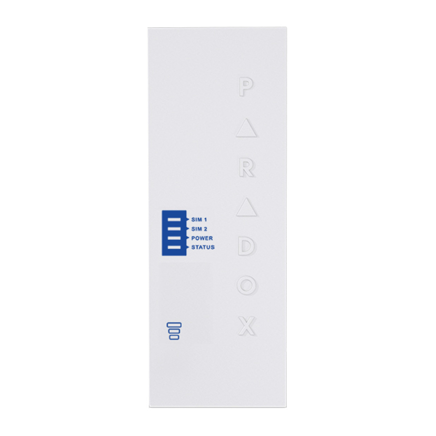
LED Functionality
| LED | Functionality |
| SIM1 and SIM2 | Slow orange flashing - Searching the network Solid blue - 4G/3G Solid orange - GSM Solid green - 2G (n/a for North and South America) Quick flashing - Exchanging data (the color of the flashing LED corresponds to the color of 4G/3G/2G or GSM depending on which is being used) Off - SIM card 1 or 2 is not installed, not active, or currently not in use |
| Power | Solid green Off - No power |
| Status | Red - Error condition, no firmware Red/Green alternating - updating firmware Green - No error and/or battery fully charged Amber - Battery charging |
| Signal Strength | Three LEDs indicate network strength |
| All LEDs (except power) | Flashing - No data communication |
Programming
In order to configure the PCS265 for reporting, you will need to first configure your SIM cards. Please note that SIM Card 1 can be configured via panel programming and SIM Card 2 via SMS.
4G/3G/2G Reporting (Serial Port Connection)
Network Provider Information
| MG/SP | EVO | Feature |
| [921] | [2960] | APN part 1 (characters 1-16) |
| [922] | [2961] | APN part 2 (characters 17-32) |
| [923] | [2962] | APN user name part 1 (1-16) |
| [924] | [2963] | APN user name part 2 (17-32) |
| [925] | [2964] | APN password part 1 (1-16) |
| [926] | [2965] | APN password part 2 (17-32) |
 This information can be obtained from your mobile network provider. | ||
Network Provider Information via SMS
| Command | Description |
| P[password].APN2.NAME. [Access Point Name] | Used to program the SIM Card 2 Access Point Name |
| P[password].APN2.USER.[Access Point Name] | Used to program the SIM Card 2 Access Point User |
| P[password].APN2.PSW.[Access Point Name] | Used to program the SIM Card 2 Access Point Password |
| P[password].APN2.CLEAR | Used to clear the SIM Card 2 Access Point Name |
| P[password].VAPN2.[CALL BACK PHONE NUMBER] | Used to view the SIM Card 2 Access Point Name information |
4G/3G/2G Reporting Options
| MG/SP | EVO | Feature | Details |
| [918] [919] | [2976] to [2983] | Account / Partition Registration | MG/SP: Sections represent account/ partition 1 and 2 EVO: Sections represent account / partition 1 to 8 |
| [806] | [2975] | [7] Off + [8] Off = landline only [7] Off + [8] On = 4G/3G/2G primary / landline backup (default) [7] On + [8] Off = landline only [7] On + [8] On = landline and 4G/3G/2G in parallel | |
| Receiver Settings | MG/SP | |||
| Receiver #: | 1 | 2 | Backup | |
| IP address* | [929] | [936] | [943] | |
| IP port ** | [930] | [937] | [944] | |
| IP address | [931] | [938] | [945] | |
| WAN 2 | [932] | [939] | [946] | |
| IP port WAN2 Receiver password | [933] | [940] | [947] | |
| Security Profile | [934] | [941] | [948] | |
| Module registration - Press [ARM] to register | [935] | [942] | [949] | |
| Receiver Settings | EVO | |||
| Receiver #: | 1 | 2 | 3 | 4 |
| IP address* | ||||
| IP port ** | ||||
| IP address | [2984] | [2986] | [2988] | [2990] |
| WAN 2 | ||||
| IP port WAN2 | ||||
| Receiver password | ||||
| Security Profile | ||||
| * For 1 or 2 digit numbers, add "0's" before the digit: e.g., 138.002.043.006 ** Default = 10000 Enter [MEM] for blank space | ||||
GSM Reporting (EBUS Connection)
Reporting Options
| MG/SP | EVO | Details |
| [805] | [2950] | [1] Off + [2] Off = landline only (default) [1] Off + [2] On = landline primary / GSM backup (default) [1] On + [2] Off = GSM primary / landline backup [1] On + [2] On = GSM only |
| [815] to [817] | [3071] to [3074] | Telephone numbers |
| [811] to [812] | [3061] to [3068] | Account numbers |
SMS Messages for Backup
| Command | Description |
| P[PASSWORD].SMS[GSM MODEM TELEPHONE #].[IPRS-7 PASSWORD] | Used to program the receiver's SMS parameters |
Additional Programming Options
SMS Language
| Language | Value | Language | Value |
| English (default) | 000 | Bulgarian | 016 |
| French | 001 | Romanian | 017 |
| Spanish | 002 | Slovak | 018 |
| Italian | 003 | Chinese | 019 |
| Swedish | 004 | Serbian | 020 |
| Polish | 005 | Malay | 021 |
| Portuguese | 006 | Slovenian | 022 |
| German | 007 | Lithuanian | 023 |
| Turkish | 008 | Finnish | 024 |
| Hungarian | 009 | Estonian | 025 |
| Czech | 010 | French Canadian | 026 |
| Dutch | 011 | Belgian | 027 |
| Croatian | 012 | Latvian | 028 |
| Greek | 013 | Albanian | 029 |
| Hebrew | 014 | Macedonian | 030 |
| Russian | 015 |
List of SMS Commands
| Command | Description | ||
| P[password].A[IP address].P[port number] | Used for 4G/3G/2G remote access | ||
| P[password].IP.[call back phone number] | Used to obtain the IP address and IP port of the PCS265 and whether or not the "bandwidth saver" option is being used | ||
| P[password].RESET | Used to reset the PCS265 | ||
| P[password].BWS.ON | Used to enable bandwidth saver mode | ||
| P[password].BWS.OFF | Used to disable bandwidth saver mode | ||
| P[password].VOLOUT.[GSM output volume] | Used to set the GSM output volume; values range between 50 to 100 | ||
| P[password].STATUS.[phone number] | Used to obtain the signal strength, signal quality, 4G/3G/2G connection status, and APN settings of the current SIM card | ||
| P[password].APN1.NAME.[Access Point Name] | Used to program the SIM Card 1 APN | ||
| P[password].APN1.USER.[Access Point Name] | Used to program the SIM card 1 APN User Name | ||
| P[password].APN1.PSW.[Access Point Name] | Used to program the SIM card 1 APN Password | ||
| P[password].APN1.CLEAR ] | Used to clear the SIM Card 1 APN | ||
| P[password].VAPN1.NAME.[Access Point Name] | Used to view the SIM card 1 APN | ||
| P[password].APN2.NAME.[Access Point Name] | Used to program the SIM card 2 APN | ||
| P[password].APN2.USER.[Access Point Name] | Used to program the SIM card 2 APN User Name | ||
| P[password].APN2.PSW.[Access Point Name] | Used to program the SIM card 2 APN Password | ||
| P[password].APN2.CLEAR | Used to clear the SIM card 2 APN | ||
| P[password].VAPN2.[CALL BACK PHONE NUMBER] | Used to view the SIM card 2 APN information | ||
| P[password].[IP1W1/ IP1W2/ IP2W1/ IP2W2/ IP3W1/ IP3W2/ IP4W1/ IP4W2].[domain name] | Set domain name for 4G/3G/2G receiver | ||
| P[password].[IP1W1/ IP1W2/ IP2W1/ IP2W2/ IP3W1/ IP3W2/IP4W1/ IP4W2].CLEAR | Clear domain name for 4G/3G/2G receiver | ||
| P[password].DNS.[ip address] | Set domain name server (DNS) IP address | ||
| P[password].DNS.CLEAR | Clear domain name server (DNS) IP address | ||
| P[password].VIP.[phone number] | Get domain name server (DNS) info | ||
| C[user code].[ARM/ OFF].A[area number], [area number], [area number]TO[area number] | Arm/Disarm | ||
| P[password].---S | Disable SWAN polling (V4.32.002 and higher) | ||
| P[password].+++S | Enable SWAN polling (V4.32.002 and higher) |
Technical Specifications
| Specifications | Description |
| RF Power | Class 4 (2W) @ 850/1900 MHz Class 2 (1W) @ 1800/1900 MHz UMTS 850/1900 @ 0.25W (America) UMTS 900/2100 @ 0.25W (Europe) |
| Antenna Bandwidth | 5 bands, wideband |
| Voltage Input | 12 VDC nominal |
| Consumption during GPRS/GSM transmission | 60mA standby 300 mA maximum |
| Encryption | 128-bit (AES) |
| SMS Protocol | 7-bit (GSM: 3GPP TS 23.038/ GSM03.38) or 16-bit (UCS2 ISO/IEC10646) |
| SIM Cards | 4G/3G GSM (2G - n/a for North and South America) |
| Humidity | 0 - 90% non-condensing |
| Operating Temperature | -20 - 50°C (-4 to 122°F) |
| Dimensions | 20.8 x 7.5 x 2 cm / 8.2 x 2.9 x 0.8 in. |
| Certifications | EN 50131-1 Grade 3 Class II, EN 50136-1 ATS Category SP5 |
Safety Note: This device may operate continuously in temperature of 55°C (131°F) for a maximum period of 7 days.
Warranty
The Limited Warranty Statement can be found on the website www.paradox.com/terms.
Patents
Your use of the Paradox product signifies your acceptance of these terms and conditions. The following US patents may apply 5,886,632 and 6,215,399. Other Canadian and international patents may apply.
©2019 Paradox Security Systems (Bahamas) Ltd. All rights reserved. Specifications may change without prior notice.

Documents / Resources
References
Download manual
Here you can download full pdf version of manual, it may contain additional safety instructions, warranty information, FCC rules, etc.
Download Paradox PCS265 - Communicator Module Installation And Programming Manual
Advertisement


Need help?
Do you have a question about the PCS265 and is the answer not in the manual?
Questions and answers