Paradox IP150+ Manual
- Installation manual (2 pages) ,
- Programming manual (2 pages) ,
- Installation manual (10 pages)
Advertisement
- 1 Introduction
- 2 Before You Begin
- 3 Installation
- 4 Attaching the IP150 + to the Panel
- 5 LED Indicators
- 6 Port Settings
- 7 Creating a Site
- 8 Configuring the IP150 + Using BlueEye
- 9 Reporting to the IPC10 Receiver
- 10 Setting Up IP Reporting at Keypad or BabyWare
- 11 Email Configuration
- 12 Firmware Upgrade
- 13 Reset IP150 + to Default Settings
- 14 Firmware Version Fallback
- 15 Technical Specifications
- 16 Documents / Resources
Introduction
The IP150 + Internet Module provides access to Paradox systems. The IP150 + reports only to the IPC10 Paradox receiver/converter and BlueEye, based on MQTT technology making it stable, fast, and reliable.
The IP150 + is remotely upgradeable from InField and the BlueEye application. It supports all Paradox + panels and should operate with most Paradox panels produced after 2012.
THINGS YOU SHOULD KNOW, PLEASE READ:
While the IP150 + programming is similar to the IP150+, there are some differences you should know:
- You can configure static IP in BlueEye installer menu for BlueEye but BlueEye does not support static IP connection and IP150 + must have internet connection.
- IP150 + reports in Contact ID format only to the IPC10 (make sure the panel is set to Contact ID reporting), and from IPC10 to CMS MLR2-DG, Ademco 685, or Ademco CID-TCP.
- IP150 + supports and supervises up to two IPC10 reporting receivers.
- When IP150 + is connected, only the BlueEye application will connect; Insite Gold will not connect to the IP150 +.
- PCS port is not enabled, the combo configuration is not supported in MQTT reporting.
Before You Begin
Make sure you have the following in order to configure your IP150 + Internet Module:

- Router
- 4-pin serial cable (included)
- CAT5 Ethernet cable (maximum 90m (295 ft.), not included)
- BlueEye app
- Connect IP150 + to the serial port on your panel and Ethernet port of your router
Installation
IP150 +
The IP150 + should be installed in the panel metal box enclosure to be tamper-protected. Clip the IP150 + to the top of the metal box, as shown in Figure 3.
Serial to the Panel
Connect the serial output of the IP150 + to the Serial port of the Paradox panels. If it is Paradox + Series, connect it to Serial1 as it is the main reporting channel, as shown in Figure 2. If the panel is powered up, the on-board LEDs will illuminate to indicate the IP150 +'s status.
Ethernet
Connect the Ethernet cable to an active Ethernet socket and the left side of the IP150 +, as shown in Figure 2.
Figure 3
Metal Box

Attaching the IP150 + to the Panel
To connect the IP150 +, plug in the Serial cable to panel, refer to Figure 2. After a few seconds, the RX/TX LED starts flashing; this indicates that the IP150 + is powered and is communicating with the panel.
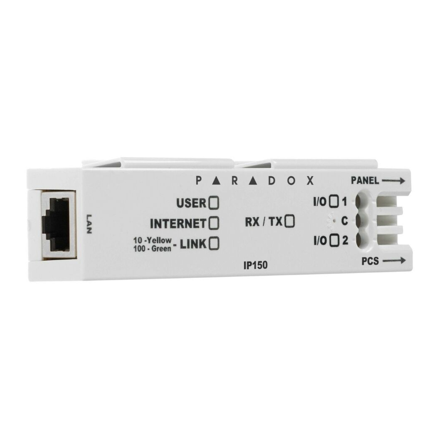
LED Indicators
| LED | Description |
| User | Green - On when a user is connected via BlueEye/BabyWare/InField/ NEware. |
| Internet | ON - Connected to Internet and connected to Swan-Q Flashing every 1 second - connected to Internet, not connected to Swan-Q (no site token) OFF - no internet |
| Link | ON - Connected to Ethernet (GREEN 100mbps Orange 10mbps,) |
| RX/TX | ON - when connected to panel Flashes when data is transmitted or received through/from panel OFF when no connection to panel |
| I/O 1 | N/A |
| I/O 2 | N/A |
Port Settings
Please make sure that the ISP or router/firewall is not blocking the following ports that need to be permanently open (TCP/UDP, and inbound and outbound):
| Port | Description (used for) |
| UDP 53 | DNS |
| UDP 123 | NTP |
| UDP 5683 | COAP (back up) |
| TCP 8883 | MQTT port SWAN and IPC10 receiver |
| TCP 443 | OTA (firmware upgrade + certificate download) |
| TCP Port 465, 587 | Usually for email server, may differ depending on the email server used. |
Creating a Site
- Open the BlueEye app.
- Select the Menu, and then select Installer Menu.
- Press on the 3-dot menu and select Create New Site.
- Enter the Panel SN, Site Name, and email address.
- Tap on Create New Site.
- Site is created.
Configuring the IP150 + Using BlueEye
Configuring IP150 + in a Connected Site

- Open the BlueEye app.
- Select the Menu and then Installer Menu; the Installer Site List screen will be displayed.
- Select the Site.
- Enter the Installer Remote connection code (previously called PC code).
- Select the Modules Programming option from the Installer Services tab.
- Select Module Configuration.
- Select IP150 +.
Reporting to the IPC10 Receiver
To configure reporting, enter at the Paradox panel via keypad, BabyWare, or the CMS Account number IP address(es) of the receiver(s), IP Port, and the security profiles (2-digit number) that indicates the supervision time. Up to two receivers can be used to report with the IP150 +. If you are currently reporting to four receivers, once you upgrade to an IP150 +, you will no longer be able to configure or report to four receivers.
NOTE: 10-digit account numbers will be supported in EVOHD+ panels, and MG+/SP+ in the future.
Security Profiles
Security profiles cannot be modified.
| ID | Supervision |
| 01 | 1200 seconds |
| 02 | 600 seconds |
| 03 | 300 seconds |
| 04 | 90 seconds |
Setting Up IP Reporting at Keypad or BabyWare
NOTE: The IP150 + can only report CID format, make sure reporting is set to CID (Ademco contact ID).
- Ensure the panel's report code format is set to Ademco Contact ID:
MG/SP: section [810]
Enter value 4 (default)
EVO/EVOHD+: section [3070]
Enter value 5 1) Enter the IP reporting account numbers (one for each partition):
MG/SP: section [918] / [919]
EVO: section [2976] to [2977] EVOHD+ section [2976] - Enter the monitoring station's IP address(es), IP port(s), and security profile(s) (information must be obtained from the monitoring station).
| MG/SP Sections | ||
| IP Receiver | #1 | #2 |
| IP Address 1 | [929] | [936] |
| IP Port 1 | [930] | [937] |
| IP Profile | [934] | [941] |
| EVOHD+ Sections | ||
| IP Receiver | Main | Backup |
| IP Address 1 | [2984] | [2986] |
| IP Port 1 |  |  |
| IP Profile | The IP profile for this receiver is the same as the Main receiver IP profile | |
| EVO Sections | ||
| IP Receiver | #1 | #2 |
| IP Address 1 | [2984] | [2986] |
| IP Port 1 |  | |
| IP Profile | ||
| MG/SP Sending IP Credentials to Receiver | ||
| IP Receiver | #1 | #2 |
| Save and Send/Status | [935] | [942] |
| EVO/EVOHD+ Sending IP Credentials to Receiver | ||
| IP Receiver | Main | Parallel |
| Save and Send/Status | [2985] | [2987] |
Notes:
The IP150 + can report only to two receivers as follows:
- For EVOHD/192, Main and Parallel OR Backup receivers can be configured.
- For EVOHD+, Main and Backup receivers can be configured (hardcoded).
- For MG+/SP+/MG/SP, Main and Parallel receivers can be configured (hardcoded).
Email Configuration
Configure the IP150 +'s email server settings.
Email Addresses
You can configure your IP150 + to send email notifications to up to four email addresses to receive notification of system events.
To configure an email address:
- Enable the Address toggle button.
- Enter the Email address. Use the test button to verify that the recipient's address is correct.
- Select the Areas and Event groups that generate email notifications.
![]()

NOTE: Enter the username without the @domain.
Firmware Upgrade
- Firmware upgrading is available from the BlueEye app using the installer Menu, or Infield software.
- Select the site from the sites list.
- Enter the PC password in the field and press Connect.
- Select Modules Programming.
- Select Modules Updates.
- Select IP150 +_LATEST.
- The list of firmware available will appear, select the firmware to use.
Reset IP150 + to Default Settings
To reset the IP150 + module to its default settings, ensure that the module is turned on and then insert a pin/straightened paper clip (or similar) into the pinhole located between the two I/O LEDs. Press down gently until you feel some resistance; hold it down for approximately five seconds. When the I/O and RX/TX LEDs start flashing, release it, and then press it again (figure 2). The I/O and RX/TX LEDs will remain lit during the reset.
Firmware Version Fallback
To revert the IP150 + module to its previously installed firmware version, unplug the power cable from the panel and insert a pin/straightened paper clip (or similar object) into the pinhole located between the two I/O LEDs. Press down gently until you feel some resistance; plug in the power cable while holding the pin down for approximately five seconds and release it when the I/O 2 LED starts flashing (figure 2). The I/O LED will turn solid and start blinking (resetting to the backup version). Once complete, the IP150 + will reboot automatically to the previously installed firmware version.
Technical Specifications
The following table provides the technical specifications for the IP150 + Internet Module.
| Specification | Description |
| Panel Compatibility | Compatible with EVOHD+, SP+, MG+, and most Paradox panels produced after 2012 |
| Upgrade | Remotely via InField or BlueEye app |
| IP Receiver | IPC10 (up to two supervised receivers simultaneously) |
| Encryption | AES 128-bit |
| IPC10 to CMS Output Format | MLR2-DG, Ademco 685, or Ademco CID-TCP |
| Current Consumption | 100 mA |
| Operating Temperature | -20 c to +50 c |
| Input Voltage | 10V to 16.5 Vdc, supplied by the panel serial port |
| Enclosure Dimensions | 10.9 x 2.7 x 2.2 cm (4.3 x 1.1 x 0.9 in) |
| Approvals | CE, EN 50136 ATS 5 Class II |
For any comments or suggestions, send an email to manualsfeedback@paradox.com.
Documents / ResourcesDownload manual
Here you can download full pdf version of manual, it may contain additional safety instructions, warranty information, FCC rules, etc.
Advertisement


Need help?
Do you have a question about the IP150+ and is the answer not in the manual?
Questions and answers