Table of Contents
Advertisement
Document Type: Service Manual
Version 1.1 10162017
SERVICE MANUAL
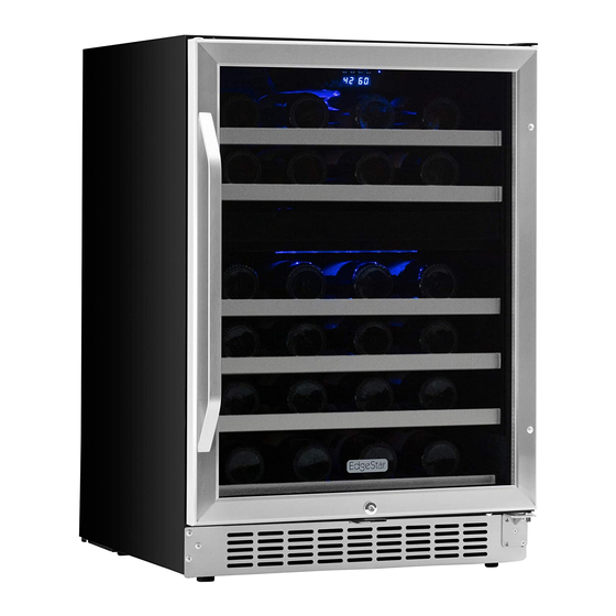
Multi Zone Cooler
MODEL:
CWR461DZ, CWR262DZ, CWF340DZ, CWR1101DZ,
CWR1551DZ, CWR1551DD, CWR1431TZ
CAUTION: READ ALL SAFETY PRECAUTIONS IN THIS
MANUAL BEFORE SERVICING THE UNIT
EdgeStar, 8606 Wall St, Suite 1800, Austin, TX 78754
support.edgestar.com • service@edgestar.com • edgestar.com
*Warranty service should be performed by an authorized service representative only.
Advertisement
Table of Contents
Troubleshooting

Subscribe to Our Youtube Channel
Related Manuals for EdgeStar CWR461DZ


Summary of Contents for EdgeStar CWR461DZ
- Page 1 CWR1551DZ, CWR1551DD, CWR1431TZ CAUTION: READ ALL SAFETY PRECAUTIONS IN THIS MANUAL BEFORE SERVICING THE UNIT EdgeStar, 8606 Wall St, Suite 1800, Austin, TX 78754 support.edgestar.com • service@edgestar.com • edgestar.com *Warranty service should be performed by an authorized service representative only.
-
Page 2: Table Of Contents
CONTENTS SAFETY PRECAUTIONS ................................2 PARTS IDENTIFICATION .................................3-7 DISASSEMBLY..................................8-22 DOOR .......................................8 WOODEN SHELVES................................8 WIRES SHELVES..................................8 LAMP………… ..................................9-12 DISPLAY BOARD BOARD & CONTROL BOARD......................12-15 POWER BOARD & TRANSFORMER ..........................15-16 SENSOR & FAN................................16-19 COMPRESSOR PTC STARTER & OVERLOAD PROTECTOR........…………………………….…….19-22 TROUBLESHOOTING.................................23-26 COMPRESSOR COMPONENTS ............................23 ANOTHER ELECTRIC COMPONENT ..........................24 SERVICE DIAGNOSIS CHART.............................25 REFRIGERATING CYCLE ..............................26... -
Page 3: Parts Identification
2. PARTS IDENTIFICATION Model:CWR461DZ Models:CWR262DZ - 3 -... - Page 4 2. PARTS IDENTIFICATION Models:CWF340DZ Models:CWR1101DZ - 4 -...
- Page 5 2. PARTS IDENTIFICATION Models:CWR1551DZ - 5 -...
- Page 6 2. PARTS IDENTIFICATION Models:CWR1551DD - 6 -...
- Page 7 2. PARTS IDENTIFICATION Models:CWR1431TZ Seamless Stainless Door Carbon Filter Light Internal Fan Shelf Upper Control Panel Door Handle Lower control Panel Door Lock Leveling foot Front Vent - 7 -...
-
Page 8: Disassembly
3. DISASSEMBLY 3-1 DOOR (Models:CWR461DZ , CWR262DZ ) 3-2 WOODEN SHELVES Loosen 2 bolts fixing the lower door axis to the lower (Models:CWR461DZ , CWR262DZ hinge to remove the door. (Figure 1) CWR1101DZ, CWR1551DZ, CWR1551DD, CWR1431TZ) Open the door completely. -
Page 9: Lamp
3. DISASSEMBLY 3-3 LAMP LED light in lower zone (Models:CWR461DZ , CWR262DZ , CWR1101DZ, CWR1551DZ , Loosen one screws. (figure 10) LED light in upper zone Loosen four screws. (figure 6) Figure screws Unplug the led light connector. (figure 11) - Page 10 3. DISASSEMBLY 2. Unplug the led light connector. (figure 15) 7. Loosen two screws. (figure 20) Screw Figure 20 Figure 15 (Models:CWR1551DD ) 3. Loosen two screws. (figure 16) LED Light in upper zone 1. Loosen four screws. (figure 21) Figure 16 Figure 21 4.
- Page 11 3. DISASSEMBLY (Models: CWR1431TZ ) LED light in lower zone LED light in upper zone 1. Remove four screws from the middle air duct board (figure 1. Loosen one screws. (figure 32) Screw Figure 32 Figure 26 Remove the middle air duct board cover. Unscrew four screws (figure 27) 2.
-
Page 12: Display Board Board & Control Board
The LED light is like below. (figure 40) Figure 44 The display board is like below. (figure 45) Figure 40 3-4 DISPLAY BOARD & CONTROL BOARD (Models:CWR461DZ, CWR262DZ, CWR1101DZ, CWR1551DZ) Loosen four screws. (figure 41) Pull out the electrical box. Figure 45 (Models:CWF340DZ) - Page 13 3. DISASSEMBLY Push up the top insert Assembly. (figure 47) Unplug all cable connectors. The control board is like below. (figure 52) Figure 47 Figure 52 Unplug the cable connector. (figure 48) (Models:CWR1551DD ) 1. Loosen four screws. (figure 53) Figure 48 Figure 53 Loosen six screws.
- Page 14 3. DISASSEMBLY 6.Loosen the display PCB board connector. Pull out the air (Models: CWR1431TZ ) duct board C.Take out the front display PCB board cover from PCB board for lower zone left side(figure 62) 1. Remove five screws from the air duct board (figure 57) Front cover Figure 62 7.
-
Page 15: Power Board & Transformer
12.Loosen the display PCB board connector. Pull out the air duct board C.Take out the front display PCB board cover from left side(figure 68) Figure 72 (Models:CWR461DZ, CWR1101DZ, CWR1551DZ) Loosen three screws. (figure 73) Figure 68 Front display PCB board cover 13. -
Page 16: Sensor & Fan
3. DISASSEMBLY power board & transformer are like below. (figure 76) power board & transformer are like below. (figure 80) Figure 76 Figure 80 3-6 SENSOR & FAN (Models:CWR1551DD) (Models:CWR262DZ) Loosen three screws. (figure 77) 1. Loosen six screws. Pull out the rear air duct cover. (figure 8 1 ) Screw Figure 77... - Page 17 3. DISASSEMBLY (Models:CWR461DZ) Loosen screw. You can replace the sensor ,heater & fan.(figure 87) Loosen six screws. Pull out the rear air duct cover. (figure 8 4 ) defrost sensor evaporator Screw screw wire housing heater cold catalyst Figure 87 Figure 84 Loosen 1 screw.
- Page 18 3. DISASSEMBLY (Models:CWF340DZ) Loosen screw. You can replace the sensor ,heater & Loosen screws. Pull out the rear air duct cover. fan.(figure 93) (figure 9 0 ) screw wire housing Screw heater sensor evaporator screw wire housing Figure 90 heater Loosen 1 screw.
-
Page 19: Compressor Ptc Starter & Overload Protector
3-7 COMPRESSOR PTC STARTER & OVERLOAD PROTECTOR (Models:CWR262DZ) 1. Remove the clamp that is used to fix the compressor junction box. (figure 96) Figure 99 (Models:CWR461DZ) Loosen one screw. (figure 100) Figure 96 2. Remove the compressor junction box. (figure 97) Figure 97 Figure 100... - Page 20 3. DISASSEMBLY Remove the compressor junction box. (figure 101) (Models:CWR1101DZ) Loosen one screw. (figure 104) Figure 101 Dismantle the compressor PTC starter and overload protector. (figure 102) Figure 104 Remove the compressor junction box. (figure 105) Figure 102 Figure 105 Dismantle the compressor PTC starter and overload protector.
- Page 21 3. DISASSEMBLY The compressor PTC starter and overload protector is 3. Dismantle the compressor PTC starter and overload like below. (figure 107) protector. (figure 110) Figure 107 (Models:CWR1551DZ, CWR1551DD) Figure 110 1、Open the box near compressor, take out the box.(figure 108) 4.
- Page 22 3. DISASSEMBLY Dismantle the compressor PTC starter and overload Dismantle the compressor PTC starter and overload protector. (figure 113) protector. (figure 116) Figure 113 Figure 116 3、 The compressor PTC starter and overload protector is like below. (figure 114) The compressor PTC starter and overload protector is like below.
-
Page 23: Troubleshooting
4. TROUBLESHOOTING 4-1 COMPRESSOR COMPONENTS Check the Check the resistance resistance of among M-C, S-C and Motor M-S in Motor Replace Compressor. Compressor. Compressor. If its normal Check the resistance Check the of two terminals in resistance of PTC-Starter. If its Replace PTC-Starter. -
Page 24: Another Electric Component
4. TROUBLESHOOTING 4-2 ANOTHER ELECTRIC COMPONENTS ▼ Cooling is impossible Compressor doesn't run. Check if current flows to the Cause. following components. a. Starting devices Shorted or broken. Poor contacting b. OLP or shorted. c. Compressor coil Coil shorted. Replace Poor contacting d. -
Page 25: Service Diagnosis Chart
4. TROUBLESHOOTING 4-3 SERVICE DIAGNOSIS CHART Problem Possible Cause Appliance does not operate. Not plugged in. The appliance is turned off. The circuit breaker tripped or a blown fuse. Appliance is not cold enough. Check the temperature control setting. External environment may require a higher setting. -
Page 26: Refrigerating Cycle
4. TROUBLESHOOTING 4-4 REFRIGERATING CYCLE ▼ Troubleshooting Chart CAUSE STATE OF UNIT STATE OF EVAPORATOR TEMPERATURE COMMENTS OF COMPRESSOR • A little refrigerant discharges Appliance does PAR TIAL Low owing sound of A little high - • Normal cooling is possible when LEAKAGE not get cold Refrigerant is heard and... -
Page 27: Description Of Pcb
5. DESCRIPTION OF PCB (Models:CWR461DZ, CWR262DZ, CWR1101DZ, CWR1551DZ) Figure 55 (Models:CWF340DZ) Figure 57 - 27 -... -
Page 28: Description Of Pcb
5. DESCRIPTION OF PCB (Models:CWR1551DD) (Models:CWR1431TZ) - 28 -... - Page 29 DATE REVISION NOTES: 9/22/2017 Initial Document 10/16/2017 Minor Text and Title Revision EdgeStar, 8606 Wall St, Suite 1800, Austin, TX 78754 support.edgestar.com • service@edgestar.com • edgestar.com *Warranty service should be performed by an authorized service representative only.
Need help?
Do you have a question about the CWR461DZ and is the answer not in the manual?
Questions and answers
Have a edge star model cwr1551dl Nothing comes on when I plug it in No compressor start up..no digital display No lights..what could be the most common issue
Common issues that could cause the EdgeStar CWR461DZ to not power on, with no compressor startup, digital display, or lights, include:
1. The cooler is not plugged in.
2. There is a power failure or insufficient power at the outlet.
3. A house fuse has blown or the circuit breaker is tripped.
Solutions:
- Ensure the unit is plugged into an outlet with sufficient power.
- Replace any blown fuse or reset the circuit breaker.
This answer is automatically generated