Sign In
Upload
Download
Table of Contents
Contents
Add to my manuals
Delete from my manuals
Share
URL of this page:
HTML Link:
Bookmark this page
Add
Manual will be automatically added to "My Manuals"
Print this page
×
Bookmark added
×
Added to my manuals
Manuals
Brands
EdgeStar Manuals
Freezer
VBR Series
Service manual
EdgeStar VBR Series Service Manual
Beverage cooler
Hide thumbs
1
Table Of Contents
2
3
4
5
6
7
8
9
10
11
12
13
14
15
16
17
18
19
20
21
22
23
24
25
26
page
of
26
Go
/
26
Contents
Table of Contents
Troubleshooting
Bookmarks
Table of Contents
Table of Contents
Contents
Safety Precautions
Electrical Safety
General Safety
Specifications
Exploded View and Parts List
Service Precautions for R600A System
Controls and Electical System
Control Functions
Alarm System
Other Functions
Test Mode
Wiring Diagram and Schematic
Sensor Resistance Table
Parts Replacement Procedures
Replacing the Ventilation Grill / Lock Assembly
Replacing the Led Light
Replacing the Control Pcb
Replacing the Power Pcb
Replacing the Evaporator Fan Motor and Temperature Sensor
Replacing the Condenser Fan Motor
Leveling the Door / Hinge Adjustments
Replacing the Door Gasket
Replacing the Evaporator Assembly
Replacing the Compressor, Compressor Ptc Starter and Overload Protector
Replacing the Filter Drier
Replacing the Condenser
Troubleshooting
Advertisement
Quick Links
1
Exploded View and Parts List
2
Controls and Electical System
3
Control Functions
4
Parts Replacement Procedures
5
Replacing the Evaporator Fan Motor and Temperature Sensor
6
Troubleshooting
Download this manual
Document Type: Service Manual
Version: V1.1 06042019
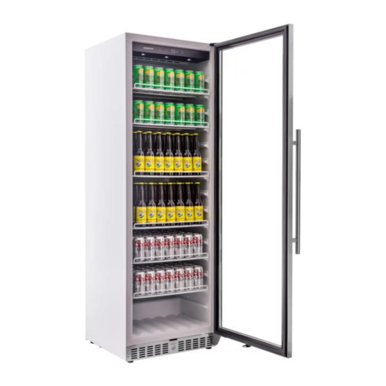
SERVICE MANUAL
EDGESTAR VBR SERIES BEVERAGE COOLER
Model:
VBR240
VBR440
VBR640
EdgeStar, 8606 Wall St, Suite 1600, Austin, TX 78754
support.edgestar.com • service@edgestar.com • edgestar.com
Table of
Contents
Previous
Page
Next
Page
1
2
3
4
5
Advertisement
Table of Contents
Need help?
Do you have a question about the VBR Series and is the answer not in the manual?
Ask a question
Questions and answers
Related Manuals for EdgeStar VBR Series
Beverage Dispenser EdgeStar VBR440 Owner's Manual
Beverage cooler (20 pages)
Freezer EdgeStar VBR240 Service Manual
Beverage cooler (26 pages)
Freezer EdgeStar VBR640 Service Manual
Beverage cooler (26 pages)
Freezer EdgeStar Upright Freezer Owner's Manual
Edgestar upright freezer owner's manual (9 pages)
Freezer EdgeStar CBR1501SG Owner's Manual
Built-in beverage cooler (17 pages)
Freezer EdgeStar CBR901SG Owner's Manual
Built-in beverge cooler (17 pages)
Freezer EdgeStar CWR461DZ Service Manual
Multi zone cooler (29 pages)
Freezer EdgeStar FP430 Owner's Manual
Portable fridge/freezer (16 pages)
Freezer EdgeStar BBR900BL Service Manual
Single zone cooler (41 pages)
Freezer EdgeStar FP430 Service Manual
Portable freezer (16 pages)
Freezer EdgeStar FP630 Service Manual
Portable freezer (10 pages)
Freezer EdgeStar CMF151L-1 Owner's Manual
Compact freezer (17 pages)
Freezer EdgeStar CMF151L-1 Owner's Manual
Compact freezer (10 pages)
Freezer EdgeStar BR1500SSOD Service Manual
15" built-in kegerator (12 pages)
Freezer EdgeStar FP430-FP860 Owner's Manual
Portable freezer (8 pages)
Freezer EdgeStar BWC120SS Owner's Manual
Beverage cooler (4 pages)
This manual is also suitable for:
Vbr240
Vbr440
Vbr640
Table of Contents
Save PDF
Print
Rename the bookmark
Delete bookmark?
Delete from my manuals?
Login
Sign In
OR
Sign in with Facebook
Sign in with Google
Upload manual
Upload from disk
Upload from URL


Need help?
Do you have a question about the VBR Series and is the answer not in the manual?
Questions and answers