
Related Manuals for Agilent Technologies 34972A


Summary of Contents for Agilent Technologies 34972A
- Page 1 Agilent 34970A/34972A Data Acquisition / Switch Unit User’s Guide Agilent Technologies...
-
Page 2: Technology Licenses
© Agilent Technologies, Inc. 2009- Technology Licenses This product utilizes Microsoft Windows 2012 CE. Agilent highly recommends that all The hardware and/or software Windows-based computers connected to No part of this manual may be repro- Windows CE instruments utilize current... -
Page 3: Safety Notices
Return the product to an outlet. Any interruption of the protec- assumes no liability of the customer’s Agilent Sales and Service Office for tive (grounding) conductor or discon- failure to comply with the require- service and repair to ensure that safety nection of the protective earth terminal ments. -
Page 4: Safety Symbols
Australian EMC Framework www.agilent.com/find/assist regulations under the terms of the Radio Communications for information on contacting Agilent in your country of specific Contains one or more of location. You can also contact your the 6 hazardous substances above the maximum... - Page 5 Note: Unless otherwise indicated, this manual applies to all serial numbers. The Agilent Technologies 34970A/34972A combines precision measurement capability with flexible signal connections for your production and development test systems. Three module slots are built into the rear of the instrument to accept any combination of data acquisition or switching modules.
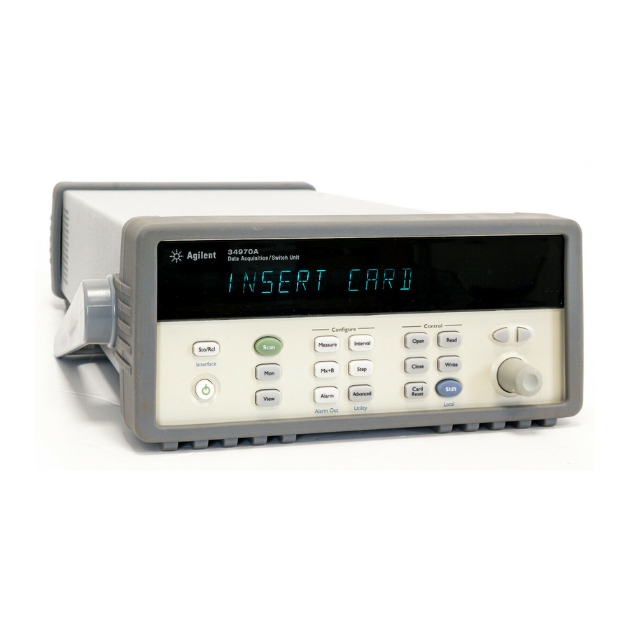
- Page 6 The Front Panel at a Glance Denotes a menu key. See the next page for details on menu operation. 1 State Storage / Remote Interface Menus 8 Advanced Measurement / Utility Menus 2 Scan Start / Stop Key 9 Low-Level Module Control Keys 3 Measurement Configuration Menu 10 Single-Channel Monitor On / Off Key 4 Scaling Configuration Menu...
- Page 7 The Front-Panel Menu at a Glance Several of the front-panel keys guide you through menus to configure various parameters of the instrument (see previous page). The following steps demonstrate the menu structure using the key. 1. Press the menu key. You are automatically guided to the first level of the menu.
- Page 8 Reading memory overflow; new readings will overwrite the oldest readings. MEM (34970A) A USB drive is connected to the instrument (annunciator on), or data is MEM (34972A) being written to or read from the USB drive (annunciator flashing). USB logging is active.
- Page 9 The 34970A Rear Panel at a Glance 1 Slot Identifier (100,200, 300) 4 Power-Line Fuse-Holder Assembly 2 Ext Trig Input / Alarm Outputs / Channel 5 Power-Line Voltage Setting Advance Input / Channel Closed Output 6 Chassis Ground Screw (for pinouts, see pages 99 and 145) 7 GPIB (IEEE-488) Interface Connector 3 RS-232 Interface Connector Use the...
- Page 10 The 34972A Rear Panel at a Glance ExtT rig / Alarms (5V) 168520 ICES/NM B-001 Line: 50/60/400 Hz Fuse: 500m AT ISM 1 (250V) 100V 120V (127V) LXI Class C N10149 240V 220V (230V) Opt. 001...
- Page 11 BenchLink Data Logger 3 at a Glance The Agilent BenchLink Data Logger 3 software provides a convenient way to collect and analyze your data. The software uses a familiar spreadsheet environment, streamlining your data gathering needs. Simply identify the measurements you want to acquire, initiate the process, and see the data displayed on the computer screen.
- Page 12 The Plug-In Modules at a Glance For complete specifications on each plug-in modules, refer to the module sections in chapter 8. 34901A 20-Channel Armature Multiplexer • 20 channels of 300 V switching • Two channels for DC or AC current measurements (100 nA to 1A) •...
- Page 13 34903A 20-Channel Actuator / General-Purpose Switch • 300 V, 1 A actuation and switching • SPDT (Form C) latching relays • Breadboard area for custom circuits • For detailed information and a module diagram, see page 205. Use this module for those applications that require high-integrity contacts or quality connections of non-multiplexed signals.
-
Page 14: A Multifunction Module
34907A Multifunction Module • Two 8-bit Digital Input/Output ports, 400 mA sink, 42 V open collector • 100 kHz Totalize input with 1 Vpp sensitivity • Two 16-bit, ±12 V Calibrated Analog Outputs • For detailed information and module block diagrams, see page 211. Use this module to sense status and control external devices such as solenoids, power relays, and microwave switches. - Page 15 Specifications Chapter 8 lists the technical specifications for the mainframe and plug-in modules. If you have questions relating to the operation of the 34970A/ 34972A, call 1-800-452-4844 in the United States, or contact your nearest Agilent Technologies Sales Office. If your 34970A/34972A fails within one year of original purchase, Agilent will replace it free of charge.
-
Page 17: Table Of Contents
To Read the Totalizer Count 51 To Output a DC Voltage 52 To Configure the Remote Interface - 34970A 53 To Configure the Remote Interface - 34972A 55 To Store the Instrument State 57 Chapter 3 System Overview Data Acquisition System Overview 60... - Page 18 Digital Output Operations 157 DAC Output Operations 159 System-Related Operations 160 Single-Channel Monitoring 171 Mass Memory (USB) Subsystem - 34972A 174 USB Drive Front Panel - 34972A 181 Remote Interface Configuration - 34970A 183 Remote Interface Configuration - 34972A 188...
- Page 19 Contents Chapter 5 Error Messages Execution Errors 219 Instrument Errors 224 Self-Test Errors 235 Calibration Errors 236 Plug-In Module Errors 239 Chapter 6 Application Programs Example Programs for Excel 7.0 243 Example Programs for C and C++ Chapter 7 Tutorial System Cabling and Connections 257 Measurement Fundamentals 265 Low-Level Signal Multiplexing and Switching 300...
-
Page 21: Chapter 1 Quick Start
Quick Start... -
Page 22: Quick Start
Quick Start One of the first things to do with your instrument is to become acquainted with the front panel. We have written the exercises in this chapter to prepare the instrument for use and help you get familiar with some of its front-panel operations. -
Page 23: To Prepare The Instrument For Use
To Prepare the Instrument for Use 1 Check the list of supplied items. Verify that you have received the following items with your instrument. If anything is missing, contact your nearest Agilent Technologies Sales Office or Agilent authorized reseller. • One power cord. - Page 24 The self-test will begin when you release the key following the beep. If the self-test fails, see the 34970A/34972A Service Guide for instructions on returning the instrument to Agilent for service.
-
Page 25: Benchlink Data Logger Software
BenchLink Data Logger Software The Agilent BenchLink Data Logger 3 software comes standard with the 34970A/34972A (if the internal DMM is ordered) and provides the basic data logger capabilities. Or, for increased capabilities, purchase the optional Agilent BenchLink Data Logger Pro software. This application provides advanced data logging and decision making with no programming required. - Page 26 Chapter 1 Quick Start BenchLink Data Logger Software On-Line Help System The software is shipped with an extensive on-line Help system to help you learn the features of the software as well as troubleshoot any problems that might arise as you are using the software. As you are installing the software, you will notice that the on-line Help system is available in several languages.
-
Page 27: To Connect Wiring To A Module
Chapter 1 Quick Start To Connect Wiring to a Module To Connect Wiring to a Module 1 Remove the module cover. 2 Connect wiring to the screw terminals. 20 AWG Typical 6 mm 3 Route wiring through strain relief. 4 Replace the module cover. Cable Tie Wrap (optional) 5 Install the module into mainframe. - Page 28 Chapter 1 Quick Start To Connect Wiring to a Module Thermocouple DC Voltage / AC Voltage / Frequency Thermocouple Types: B, E, J, K, N, R, S, T Ranges: 100 mV, 1 V, 10 V, 100 V, 300 V See page 351 for thermocouple color codes. 2-Wire Ohms / RTD / Thermistor 4-Wire Ohms / RTD ...
-
Page 29: To Set The Time And Date
Chapter 1 Quick Start To Set the Time and Date To Set the Time and Date All readings during a scan are automatically time stamped and stored in non-volatile memory. In addition, alarm data is time stamped and stored in a separate non-volatile memory queue. 1 Set the time of day. -
Page 30: To Configure A Channel For Scanning
Chapter 1 Quick Start To Configure a Channel for Scanning To Configure a Channel for Scanning Any channel that can be “read” by the instrument can also be included in a scan. This includes readings on multiplexer channels, a read of a digital port, or a read of the count on a totalizer channel. - Page 31 Chapter 1 Quick Start To Configure a Channel for Scanning Note: Press to sequentially step through the scan list and take a measurement on each channel (readings are not stored in memory). This is an easy way to verify your wiring connections before initiating the scan. 3 Run the scan and store the readings in non-volatile memory.
-
Page 32: To Copy A Channel Configuration
Chapter 1 Quick Start To Copy a Channel Configuration To Copy a Channel Configuration After configuring a channel to be included in the scan list, you can copy that same configuration to other channels in the instrument (including digital channels on the multifunction module). This feature makes it easy to configure several channels for the same measurement. -
Page 33: To Close A Channel
Chapter 1 Quick Start To Close a Channel To Close a Channel On the multiplexer and switch modules, you can close and open individual relays on the module. However, note that if you have already configured any multiplexer channels for scanning, you cannot independently close and open individual relays on that module. -
Page 34: If The Instrument Does Not Turn On
The instrument is shipped from the factory with a 500 mA fuse installed. This is the correct fuse for all line voltages. See the next page if you need to replace the power-line fuse. To replace the 500 mAT, 250 V fuse, order Agilent part number 2110-0458. - Page 35 2 Remove the line voltage selector from the fuse-holder assembly from the rear panel. assembly. Fuse: 500 mAT (for all line voltages) Agilent Part Number: 2110-0458 3 Rotate the line-voltage selector until the 4 Replace the fuse-holder assembly in the correct voltage appears in the window.
-
Page 36: To Adjust The Carrying Handle
Chapter 1 Quick Start To Adjust the Carrying Handle To Adjust the Carrying Handle To adjust the position, grasp the handle by the sides and pull outward. Then, rotate the handle to the desired position. Bench-top viewing position Carrying position... -
Page 37: To Rack Mount The Instrument
You can mount the instrument in a standard 19-inch rack cabinet using one of three optional kits available. Instructions and mounting hardware are included with each rack-mounting kit. Any Agilent System II instrument of the same size can be rack-mounted beside the 34970A/ 34972A. - Page 38 Chapter 1 Quick Start To Rack Mount the Instrument To rack mount a single instrument, order adapter kit 5063-9240. To rack mount two instruments side-by-side, order lock-link kit 5061-9694 and flange kit 5063-9212. Be sure to use the support rails inside the rack cabinet. To install one or two instruments in a sliding support shelf, order shelf 5063-9255, and slide kit 1494-0015 (for a single instrument, also order filler panel 5002-3999).
-
Page 39: Chapter 2 Front-Panel Overview
Front-Panel Overview... - Page 40 • To Output a DC Voltage, on page 52 • To Configure the Remote Interface - 34970A, on page 53 • To Configure the Remote Interface - 34972A, on page 55 • To Store the Instrument State, on page 57...
-
Page 41: Front-Panel Menu Reference
Chapter 2 Front-Panel Overview Front-Panel Menu Reference Front-Panel Menu Reference This section gives an overview of the front-panel menus. The menus are designed to automatically guide you through all parameters required to configure a particular function or operation. The remainder of this chapter contains examples of using the front-panel menus. - Page 42 • View the first 20 alarms in the alarm queue (reading and time alarm occurred). • View up to 10 errors (34970A) or 20 errors (34972A) in the error queue. • Read the number of cycles for the displayed relay (relay maintenance feature).
- Page 43 • Select the GPIB address. • Configure the RS-232 interface (baud rate, parity, and flow control). Configure the remote interface (34972A). • Configure the LAN settings (IP Address, Hostname, DHCP, etc.) • Configure the USB settings (Enable, USB ID, etc.)
-
Page 44: To Monitor A Single Channel
Chapter 2 Front-Panel Overview To Monitor a Single Channel To Monitor a Single Channel You can use the Monitor function to continuously take readings on a single channel, even during a scan. This feature is useful for troubleshooting your system before a test or for watching an important signal. -
Page 45: To Set A Scan Interval
Chapter 2 Front-Panel Overview To Set a Scan Interval To Set a Scan Interval You can set the instrument’s internal timer to automatically scan at a specific interval (e.g., start a new scan sweep every 10 seconds) or when an external TTL trigger pulse is received. You can configure the instrument to scan continuously or to stop after sweeping through the scan list a specified number of times. -
Page 46: To Apply Mx+B Scaling To Measurements
Chapter 2 Front-Panel Overview To Apply Mx+B Scaling to Measurements To Apply Mx+B Scaling to Measurements The scaling function allows you to apply a gain and offset to all readings on a specified multiplexer channel during a scan. In addition to setting the gain (“M”) and offset (“B”) values, you can also specify a custom measurement label for your scaled readings (RPM, PSI, etc.). -
Page 47: To Configure Alarm Limits
Chapter 2 Front-Panel Overview To Configure Alarm Limits To Configure Alarm Limits The instrument has four alarms which you can configure to alert you when a reading exceeds specified limits on a channel during a scan. You can assign a high limit, a low limit, or both to any configured channel in the scan list. - Page 48 Chapter 2 Front-Panel Overview To Configure Alarm Limits 4 Set the limit value. The alarm limit values are stored in non-volatile memory for the specified channels. The default values for the high and low limits are “0”. The low limit must always be less than or equal to the high limit, even if you are using only one of the limits.
-
Page 49: To Read A Digital Input Port
Chapter 2 Front-Panel Overview To Read a Digital Input Port To Read a Digital Input Port The multifunction module (34907A) has two non-isolated 8-bit input/output ports which you can use for reading digital patterns. You can read the live status of the bits on the port or you can configure a scan to include a digital read. -
Page 50: To Write To A Digital Output Port
Chapter 2 Front-Panel Overview To Write to a Digital Output Port To Write to a Digital Output Port The multifunction module (34907A) has two non-isolated 8-bit input/output ports which you can use for outputting digital patterns. 1 Select the Digital Output port. Select the slot containing the multifunction module and continue turning the knob until DIN is displayed (channel 01 or 02). -
Page 51: To Read The Totalizer Count
Chapter 2 Front-Panel Overview To Read the Totalizer Count To Read the Totalizer Count The multifunction module (34907A) has a 26-bit totalizer which can count pulses at a 100 kHz rate. You can manually read the totalizer count or you can configure a scan to read the count. 1 Select the totalizer channel. -
Page 52: To Output A Dc Voltage
Chapter 2 Front-Panel Overview To Output a DC Voltage To Output a DC Voltage The multifunction module (34907A) has two analog outputs capable of outputting calibrated voltages between ±12 volts. 1 Select a DAC Output channel. Select the slot containing the multifunction module and continue turning the knob until DAC is displayed (channel 04 or 05). -
Page 53: To Configure The Remote Interface - 34970A
3 Save the change and exit the menu. Note: Your computer’s GPIB interface card has its own address. Be sure to avoid using the computer’s address for any instrument on the interface bus. Agilent’s GPIB interface cards generally use address “21”. - Page 54 Chapter 2 Front-Panel Overview To Configure the Remote Interface - 34970A RS-232 Configuration 1 Select the RS-232 interface. RS-232 2 Select the baud rate. Select one of the following: 1200, 2400, 4800, 9600, 19200, 38400, 57600 (factory setting), or 115200 baud. 19200 BAUD 3 Select the parity and number of data bits.
-
Page 55: To Configure The Remote Interface - 34972A
Chapter 2 Front-Panel Overview To Configure the Remote Interface - 34972A To Configure the Remote Interface - 34972A The instrument is shipped with both a Local Area Network (LAN) interface and a Universal Serial Bus (USB) interface. Both interfaces can be enabled at the same time and both interfaces are selected when the instrument is shipped from the factory. - Page 56 Chapter 2 Front-Panel Overview To Configure the Remote Interface - 34972A USB Configuration 1 Select the USB interface. USB INTERFACE 2 Enable or disable the USB interface. Select either USB ENABLED or USB DISABLED. USB ENABLED 3 View the USB ID String The instrument will display its USB identification (USB ID) string.
-
Page 57: To Store The Instrument State
Chapter 2 Front-Panel Overview To Store the Instrument State To Store the Instrument State You can store the instrument state in one of five non-volatile storage locations. A sixth storage location automatically holds the power-down configuration of the instrument. When power is restored, the instrument can automatically return to its state before power-down (a scan in progress before power-down will also be resumed). - Page 58 Chapter 2 Front-Panel Overview To Store the Instrument State...
-
Page 59: Chapter 3 System Overview
System Overview... -
Page 60: Data Acquisition System Overview
• Control Output, on page 83 Data Acquisition System Overview You can use the Agilent 34970A/34972A as a stand-alone instrument, but there are many applications where you will want to take advantage of the built-in PC connectivity features. A typical data acquisition system is shown below. -
Page 61: Chapter 3 System Overview Data Acquisition System Overview
DMM is ordered). styles Data transfers up to Data transfers up to 85,000 characters/sec. 750,000 characters/sec. You can overcome these cable length limitation using special communications hardware. For example, you can use the Agilent E5810A LAN-to-GPIB Gateway interface or a serial modem. - Page 62 A variety of software is available to configure your data acquisition hardware and manipulate and display your measurement data. One particularly useful feature is 34972A’s Web Interface. Simply enter the IP address of your instrument in your browser’s navigation bar to launch the Web Interface.
- Page 63 Data Logging and Monitoring Agilent BenchLink Data Logger 3, which is included with your 34970A/ 34972A is a Windows®-based application that makes it easy to use the instrument with your PC for gathering and analyzing measurements. Use this software to set up your test, acquire and archive measurement data, and perform real-time display and analysis of your measurements.
- Page 64 PC connectivity. The 34970A is shipped with both an GPIB (IEEE-488) interface and an RS- 232 interface. Only one interface can be enabled at a time. The 34972A is shipped with Local Area Network (LAN) and Universal Serial Bus (USB) connectivity.
- Page 65 Plug-In Modules The 34970A/34972A offers a complete selection of plug-in modules to give you high-quality measurement, switching, and control capabilities. The plug-in modules communicate with the floating logic via the internal isolated digital bus.
- Page 66 Chapter 3 System Overview Data Acquisition System Overview Model Number Module Name Common Uses Measurement Input 34901A 20-Channel Mux with T/C Scanning and direct measurement of Compensation temperature, voltage, resistance, frequency, and current (34901A only) 34902A 16-Channel Reed Mux with T/C using the internal DMM.
- Page 67 Chapter 3 System Overview Data Acquisition System Overview System Cabling The plug-in modules have screw-terminal connectors to make it easy to connect your system cabling. The type of cabling that you use to connect your signals, transducers, and sensors to the module is critical to measurement success.
- Page 68 Chapter 3 System Overview Data Acquisition System Overview Transducers and Sensors Transducers and sensors convert a physical quantity into an electrical quantity. The electrical quantity is measured and the result is then converted to engineering units. For example, when measuring a thermocouple, the instrument measures a DC voltage and mathematically converts it to a corresponding temperature in °C, °F, or Measurement...
-
Page 69: Alarm Limits
Data Acquisition System Overview Alarm Limits The 34970A/34972A has four alarm outputs which you can configure to alert you when a reading exceeds specified limits on a channel during a scan. You can assign a high limit, a low limit, or both to any configured channel in the scan list. -
Page 70: Signal Routing And Switching
Signal Routing and Switching The switching capabilities of the plug-in modules available with the 34970A/34972A provide test system flexibility and expandability. You can use the switching plug-in modules to route signals to and from your test system or multiplex signals to the internal DMM or external instruments. - Page 71 Chapter 3 System Overview Signal Routing and Switching Multiplexer Switching Multiplexers allow you to connect one of multiple channels to a common channel, one at a time. A simple 4-to-1 multiplexer is shown below. When you combine a multiplexer with a measurement device, like the internal DMM, you create a scanner.
- Page 72 Chapter 3 System Overview Signal Routing and Switching Matrix Switching A matrix switch connects multiple inputs to multiple outputs and therefore offers more switching flexibility than a multiplexer. Use a matrix for switching low-frequency (less than 10 MHz) signals only. A matrix is arranged in rows and columns. For example, a simple 3x3 matrix could be used to connect three sources to three test points as shown below.
- Page 73 Chapter 3 System Overview Signal Routing and Switching Form C (SPDT) Switching The 34903A Actuator contains 20 Form C switches (also called single-pole, double-throw). You can use Form C switches to route signals but they are typically used to control external devices.
-
Page 74: Measurement Input
Chapter 3 System Overview Measurement Input Measurement Input The 34970A/34972A allows you to combine a DMM (either internal or external) with multiplexer channels to create a scan. During a scan, the instrument connects the DMM to the configured multiplexer channels one at a time and makes a measurement on each channel. - Page 75 Chapter 3 System Overview Measurement Input The internal DMM provides a universal input front-end for measuring a variety of transducer types without the need for additional external signal conditioning. The internal DMM includes signal conditioning, amplification (or attenuation), and a high resolution (up to 22 bits) analog-to-digital converter.
- Page 76 You can select the resolution and reading speed from 6 digits (22 bits) at 3 readings per second to 4 digits (16 bits) at up to 600 readings per second. The Advanced menu from the 34970A/34972A front panel allows you to control the integration period for precise rejection of noise signals.
- Page 77 Chapter 3 System Overview Measurement Input Main Processor The main processor, located in the floating logic section, controls the input signal conditioning, ranging, and the ADC. The main processor accepts commands from, and sends measurement results to, the earth-referenced logic section. The main processor synchronizes measurements during scanning and control operations.
- Page 78 Chapter 3 System Overview Measurement Input You can configure the event or action that controls the onset of each sweep through the scan list (a sweep is one pass through the scan list): • You can set the instrument’s internal timer to automatically scan at a specific interval as shown below.
-
Page 79: Scanning With External Instruments
Scanning with External Instruments If your application doesn’t require the built-in measurement capabilities of the 34970A/34972A, you can order it without the internal DMM. In this configuration, you can use the 34970A/34972A for signal routing or control applications. If you install a multiplexer plug-in module, you can use the 34970A/34972A for scanning with an external instrument. - Page 80 Chapter 3 System Overview Measurement Input To control scanning with an external instrument, two control lines are provided. When the 34970A/34972A and the external instrument are properly configured, you can synchronize a scan sequence between the two. Channel Closed OUT...
- Page 81 Chapter 3 System Overview Measurement Input The Multifunction Module The multifunction module (34907A) adds two additional measurement input capabilities to the system: digital input and event totalize. The multifunction module also contains a dual voltage output (DAC) which is described in more detail on page 68. Digital Input The multifunction module has two non-isolated 8-bit input/output ports which you can use for reading digital patterns.
- Page 82 Chapter 3 System Overview Measurement Input Totalizer The multifunction module has a 26-bit totalizer which can count pulses at a 100 kHz rate. You can manually read the totalizer count or you can configure a scan to read the count. 26 Bits Totalize Channel 03...
-
Page 83: Control Output
Control Output Control Output In addition to signal routing and measurement, you can also use the 34970A/34972A to provide simple control outputs. For example, you can control external high-power relays using the actuator module or a digital output channel. The Multifunction Module The multifunction module (34907A) adds two additional control output capabilities to the system: digital output and voltage (DAC) output. - Page 84 Chapter 3 System Overview Control Output Voltage (DAC) Output The multifunction module has two analog outputs capable of outputting calibrated voltages between ±12 volts with 16 bits of resolution. Each DAC (Digital-to-Analog Converter) channel can be used as a programmable voltage source for analog input control of other devices.
- Page 85 Chapter 3 System Overview Control Output The Actuator / General Purpose Switch You can think of the 34903A Actuator as a control output because it is often used to control external power devices. The actuator provides 20 independent, isolated Form C (SPDT) switches. Channel Open Channel Closed (NC Contact Connected)
- Page 86 Chapter 3 System Overview Control Output For control applications, the actuator has the following advantages: • Higher voltage and power rating than the digital output channels. The actuator switches can also be used to control power devices. • When used with high-power devices, however, it is critical that you provide protection to the switch from capacitive and inductive loads to ensure maximum relay life (for more information on attenuators, see the discussion on page 309).
-
Page 87: Chapter 4 Features And Functions
Features and Functions... -
Page 88: Features And Functions
Features and Functions You will find that this chapter makes it easy to look up all the details about a particular feature of the 34970A/34972A. Whether you are operating the instrument from the front panel or over the remote interface, this chapter will be useful. This chapter is divided into the following sections: •... -
Page 89: Scpi Language Conventions
• A vertical bar (| ) separates multiple parameter choices. Rules for Using a Channel List Many of the SCPI commands for the 34970A/34972A include a scan_list or ch_list parameter, which allow you to specify one or more channels. The channel number has a form (@scc), where s is the slot number (100, 200, or 300) and cc is the channel number. -
Page 90: Scanning
Chapter 4 Features and Functions Scanning Scanning The instrument allows you to combine a DMM (either internal or external) with multiplexer channels to create a scan. During a scan, the instrument connects the DMM to the configured multiplexer channels one at a time and makes a measurement on each channel. Any channel that can be “read”... - Page 91 Chapter 4 Features and Functions Scanning • You can store up to 50,000 readings in non-volatile memory during a scan. Readings are stored only during a scan and all readings are automatically time stamped. If memory overflows (the MEM annunciator will turn on), a status register bit is set and new readings will overwrite the first readings stored (the most recent readings are always preserved).
- Page 92 • If the internal DMM is installed and enabled, the instrument will automatically use it for scanning. For externally-controlled scans, you must either remove the internal DMM from the 34970A/34972A or disable it (see “Internal DMM Disable” on page 145).
-
Page 93: Power Failure
Chapter 4 Features and Functions Scanning Power Failure • When shipped from the factory, the instrument is configured to automatically recall the power-down state when power is restored. In this configuration, the instrument will automatically recall the instrument state at power-down and resume a scan in progress. If you do not want the power-down state to be recalled when power is restored, send the MEMory:STATe:RECall:AUTO OFF command (also see the Utility menu);... - Page 94 Chapter 4 Features and Functions Scanning Adding Channels to a Scan List Before you can initiate a scan, you must configure the channels to be scanned and set up a scan list (these two operations occur simultaneously from the front panel). The instrument automatically scans the configured channels in ascending order from slot 100 through slot 300.
- Page 95 The INITiate command stores readings in memory. Use the FETCh? command to retrieve stored readings from memory. See the Agilent 34970A/34972A Programmer’s Reference Help for more information on using these commands. • When you reconfigure a channel and add it to the scan list using MEASure? or CONFigure, it is important to note that the previous configuration on that channel is lost.
- Page 96 Chapter 4 Features and Functions Scanning Scan Interval You can configure the event or action that controls the onset of each sweep through the scan list (a sweep is one pass through the scan list): • You can set the instrument’s internal timer to automatically scan at a specific interval.
- Page 97 Chapter 4 Features and Functions Scanning • You can set the scan interval to any value between 0 seconds and 99:59:59 hours (359,999 seconds), with 1 ms resolution. • Once you have initiated the scan, the instrument will continue scanning until you stop it or until the scan count is reached. See “Scan Count”...
- Page 98 Chapter 4 Features and Functions Scanning Scan Once In this configuration, the instrument waits for either a front-panel key press or a remote interface command before sweeping through the scan list. • All readings from the scan are stored in non-volatile memory. Readings accumulate in memory until the scan is terminated (until the scan count is reached or until you abort the scan).
- Page 99 Chapter 4 Features and Functions Scanning External Scanning In this configuration, the instrument sweeps through the scan list once each time a low-going TTL pulse is received on the rear-panel Ext Trig Input line (pin 6). Input Ext Trig Input >...
- Page 100 Chapter 4 Features and Functions Scanning • Remote Interface Operation: The following program segment configures the instrument for an External Scan. Select the external trigger configuration TRIG:SOURCE EXT Sweep the scan list 2 times TRIG:COUNT 2 Initiate the scan INIT Note: To stop a scan, send the ABORt command.
- Page 101 Chapter 4 Features and Functions Scanning • Front-Panel Operation: SCAN ON ALARM To enable the Monitor function select the desired channel and then press . To initiate the scan, press . When an alarm event occurs, the scan starts and readings are stored in memory. Note: To stop a scan, press and hold •...
- Page 102 Chapter 4 Features and Functions Scanning Scan Count You can specify the number of times the instrument will sweep through the scan list. When the specified number of sweeps have occurred, the scan stops. • Select a scan count between 1 to 50,000 scan sweeps, or continuous. •...
- Page 103 Chapter 4 Features and Functions Scanning • Front-Panel Operation: 00020 SCANS The default is CONTINUOUS. To set the count to a value between 1 and 50,000 scans, turn the knob clockwise and enter a number. • Remote Interface Operation: TRIG:COUNT 20 Note: To configure a continuous scan, send TRIG:COUNT INFINITY.
-
Page 104: Reading Format
Chapter 4 Features and Functions Scanning Reading Format During a scan, the instrument automatically adds a time stamp to all readings and stores them in non-volatile memory. Each reading is stored with measurement units, time stamp, channel number, and alarm status information. -
Page 105: Channel Delay
Chapter 4 Features and Functions Scanning Channel Delay You can control the pace of a scan sweep by inserting a delay between multiplexer channels in the scan list (useful for high-impedance or high- capacitance circuits). The delay is inserted between the relay closure and the actual measurement on the channel. -
Page 106: Automatic Channel Delays
Chapter 4 Features and Functions Scanning Automatic Channel Delays If you do not specify a channel delay, the instrument selects a delay for you. The delay is determined by function, range, integration time, and AC filter setting as shown below. DC Voltage, Thermocouple, DC Current (for all ranges): Integration Time Channel Delay... -
Page 107: Viewing Readings Stored In Memory
Chapter 4 Features and Functions Scanning • Front-Panel Operation: CH DELAY AUTO • Remote Interface Operation: The following command enables an automatic channel delay on channel 01. ROUT:CHAN:DELAY:AUTO ON,(@101) Selecting a specific channel delay using the ROUTe:CHANnel:DELay command disables the automatic channel delay. Viewing Readings Stored in Memory During a scan, the instrument automatically adds a time stamp to all readings and stores them in non-volatile memory. - Page 108 Chapter 4 Features and Functions Scanning • While a scan is running, the instrument automatically stores the minimum and maximum readings and calculates the average for each channel. You can read these values at any time, even during a scan. •...
- Page 109 Chapter 4 Features and Functions Scanning • Front-Panel Operation: From the front panel, data is available for the last 100 readings on each channel readings taken during a scan (all of the data is available from the remote interface). After turning the knob to the desired channel, press the keys to choose the data that you want to view for the selected channel as shown below...
- Page 110 Chapter 4 Features and Functions Scanning • Remote Interface Operation: The following command retrieves stored readings from memory (the readings are not erased). FETCH? Use the following commands to query the statistics on the readings stored in memory for a specific channel. These commands do not remove the data from memory.
-
Page 111: Scanning With External Instruments
Scanning with External Instruments If your application doesn’t require the built-in measurement capabilities of the 34970A/34972A, you can order it without the internal DMM. In this configuration, you can use the 34970A/34972A for signal routing or control applications. If you install a multiplexer plug-in module, you can use the 34970A/34972A for scanning with an external instrument. - Page 112 External connections are required to synchronize the scan sequence between the 34970A/34972A and the external instrument. The 34970A/ 34972A must notify the external instrument when a relay is closed and settled (including channel delay). The 34970A/34972A outputs a Channel Closed pulse from pin 5 on the rear-panel connector (see previous page).
- Page 113 Interval” on page 80. • You can configure the event or action that notifies the 34970A/ 34972A to advance to the next channel in the scan list. Note that the Channel Advance source shares the same sources as the scan interval.
- Page 114 Chapter 4 Features and Functions Scanning with External Instruments • Remote Interface Operation: The following program segment configures the instrument for an externally controlled scan. Select the scan interval TRIG:SOUR TIMER Select the channel advance source ROUT:CHAN:ADV:SOUR EXT Set the scan interval to 5 seconds TRIG:TIMER 5 Sweep the scan list 2 times TRIG:COUNT 2...
-
Page 115: General Measurement Configuration
Chapter 4 Features and Functions General Measurement Configuration General Measurement Configuration This section contains general information to help you configure the instrument for making measurements during a scan. Since these parameters are used by several measurement functions, the discussion is combined into one common section. - Page 116 Chapter 4 Features and Functions General Measurement Configuration • For frequency and period measurements, the "range" parameter is used to compute a specific measurement resolution (see the Agilent 34970A/34972A Programmer’s Reference Help for details). When specifying a (non-default) resolution, both the range and resolution parameters must be specified within the MEASure? and CONFigure commands.
-
Page 117: Measurement Resolution
Chapter 4 Features and Functions General Measurement Configuration Measurement Resolution Resolution is expressed in terms of number of digits the instrument can measure or display on the front panel. You can set the resolution to 4, 5, or 6 full digits, plus a “½” digit which can only be a “0” or “1”. To increase your measurement accuracy and improve noise rejection, select 6½... - Page 118 Chapter 4 Features and Functions General Measurement Configuration • The specified resolution is used for all measurements on the selected channel. If you have applied Mx+B scaling or have assigned alarms to the selected channel, those measurements are also made using the specified resolution.
- Page 119 Chapter 4 Features and Functions General Measurement Configuration • Remote Interface Operation: Specify the resolution in the same units as the measurement function, not in number of digits. For example, if the function is DC volts, specify the resolution in volts. For frequency, specify the resolution in hertz.
- Page 120 Chapter 4 Features and Functions General Measurement Configuration Custom A/D Integration Time Integration time is the period of time that the instrument’s analog-to-digital (A/D) converter samples the input signal for a measurement. Integration time affects the measurement resolution (for better resolution, use a longer integration time) and measurement speed (for faster measurements, use a shorter integration time).
- Page 121 Chapter 4 Features and Functions General Measurement Configuration • The instrument selects 1 PLC when the measurement function is changed and after a Factory Reset (*RST command). An Instrument Preset (SYSTem:PRESet command) or Card Reset (SYSTem:CPON command) does not change the integration time setting. •...
- Page 122 Chapter 4 Features and Functions General Measurement Configuration Autozero When autozero is enabled (default), the instrument internally disconnects the input signal following each measurement, and takes a zero reading. It then subtracts the zero reading from the preceding reading. This prevents offset voltages present on the instrument’s input circuitry from affecting measurement accuracy.
-
Page 123: Temperature Measurement Configuration
Chapter 4 Features and Functions Temperature Measurement Configuration Temperature Measurement Configuration This section contains information to help you configure the instrument for making temperature measurements. For more information on the types of temperature transducers, see “Temperature Measurements” starting on page 267. The instrument supports direct measurement of thermocouples, RTDs, and thermistors. -
Page 124: Thermocouple Measurements
Chapter 4 Features and Functions Temperature Measurement Configuration Thermocouple Measurements To connect a thermocouple to the module’s screw terminals, see page 28. • The instrument supports the following thermocouple types: B, E, J, K, N, R, S, and T using ITS-90 software conversions. The default is a J-Type thermocouple. - Page 125 Chapter 4 Features and Functions Temperature Measurement Configuration • The thermocouple check feature allows you to verify that your thermocouples are properly connected to the screw terminals for measurements. If you enable this feature, the instrument measures the channel resistance after each thermocouple measurement to ensure a proper connection.
- Page 126 Chapter 4 Features and Functions Temperature Measurement Configuration • Remote Interface Operation: You can use the MEASure? or CONFigure command to select the probe type and thermocouple type. For example, the following statement configures channel 301 for a J- type thermocouple measurement. CONF:TEMP TC,J,(@301) You can also use the SENSe command to select the probe type and thermocouple type.
-
Page 127: Rtd Measurements
Chapter 4 Features and Functions Temperature Measurement Configuration RTD Measurements To connect an RTD to the module’s screw terminals, see page 28. • The instrument supports RTDs with = 0.00385 (DIN / IEC 751) using ITS-90 software conversions or = 0.00391 using IPTS-68 ... - Page 128 Chapter 4 Features and Functions Temperature Measurement Configuration • Remote Interface Operation: You can use the MEASure? or CONFigure command to select the probe type and RTD type. For example, the following statement configures channel 301 for 2-wire measurements of an RTD with = 0.00385 (use “85” to specify = 0.00385 or “91”...
-
Page 129: Thermistor Measurements
Chapter 4 Features and Functions Temperature Measurement Configuration Thermistor Measurements To connect a thermistor to the module’s screw terminals, see page 28. • The instrument supports 2.2 k (44004), 5 k (44007), and 10 k (44006) thermistors. • Front-Panel Operation: To select the thermistor function for the active channel, choose the following items. -
Page 130: Voltage Measurement Configuration
Chapter 4 Features and Functions Voltage Measurement Configuration Voltage Measurement Configuration To connect voltage sources to the module’s screw terminals, see page 28. This section contains information to help you configure the instrument for making voltage measurements. The instrument can measure DC and true RMS ac-coupled voltages on the measurement ranges shown below. -
Page 131: Ac Low Frequency Filter
Chapter 4 Features and Functions Voltage Measurement Configuration • Remote Interface Operation: You can enable or disable the automatic input resistance mode on the specified channels. With AUTO OFF (default), the input resistance is fixed at 10 M for all ranges. With AUTO ON, the input resistance is set to >10 G... -
Page 132: Resistance Measurement Configuration
Chapter 4 Features and Functions Resistance Measurement Configuration Resistance Measurement Configuration To connect resistances to the module’s screw terminals, see page 28. This section contains information to help you configure the instrument for making resistance measurements. Use the 2-wire method for ease of wiring and higher density or the 4-wire method for improved measurement accuracy. -
Page 133: Current Measurement Configuration
Chapter 4 Features and Functions Current Measurement Configuration Current Measurement Configuration To connect a current source to the module’s screw terminals, see page 28. This section contains information to help you configure the instrument for making current measurements on the 34901A multiplexer module. This module has two fused channels for direct DC and AC current measurements on the measurement ranges shown below. - Page 134 Chapter 4 Features and Functions Current Measurement Configuration • Front-Panel Operation: First, select the AC current (or AC voltage) function on the active channel. Then, go to the Advanced menu and select the slow filter (3 Hz), medium filter (20 Hz), or fast filter (200 Hz) for the active channel.
-
Page 135: Frequency Measurement Configuration
Chapter 4 Features and Functions Frequency Measurement Configuration Frequency Measurement Configuration To connect an AC source to the module’s screw terminals, see page 28. Low Frequency Timeout The instrument uses three different timeout ranges for frequency measurements. The instrument selects a slow, medium, or fast timeout based on the input frequency that you specify for the selected channels. -
Page 136: Mx+B Scaling
Chapter 4 Features and Functions Mx+B Scaling Mx+B Scaling The scaling function allows you to apply a gain and offset to all readings on a specified multiplexer channel during a scan. In addition to setting the gain (“M”) and offset (“B”) values, you can also specify a custom measurement label for your scaled readings (RPM, PSI, etc.). - Page 137 4-wire resistance measurement with scaling. For more information, refer to “Strain Gage Measurements” on page 295. Note: Agilent BenchLink Data Logger 3 software has built-in strain gage measurement capability. Use the following equations to calculate the gain and offset.
- Page 138 Chapter 4 Features and Functions Mx+B Scaling • The maximum gain allowed is ±1E+15 and the maximum offset allowed is ±1E+15. • The MEASure? and CONFigure commands automatically set the gain (“M”) to 1 and offset (“B”) to 0. • A Factory Reset (*RST command) turns off scaling and clears the scaling values on all channels.
-
Page 139: Alarm Limits
Chapter 4 Features and Functions Alarm Limits Alarm Limits The instrument has four alarms which you can configure to alert you when a reading exceeds specified limits on a channel during a scan. You can assign a high limit, a low limit, or both to any configured channel in the scan list. - Page 140 Chapter 4 Features and Functions Alarm Limits • You can assign an alarm to any configured channel and multiple channels can be assigned to the same alarm number. However, you cannot assign alarms on a specific channel to more than one alarm number.
- Page 141 Chapter 4 Features and Functions Alarm Limits • Alarms are logged in the alarm queue only when a reading crosses a limit, not while it remains outside the limit and not when it returns to within limits. Alarm Event No Alarm Upper Limit Lower Limit •...
- Page 142 SCPI status system. You can configure the instrument to use the status system to generate a Service Request (SRQ) when alarms are generated. See the Agilent 34970A/34972A Programmer’s Reference Help for more information. • The default values for the upper and lower alarm limits are “0”. The lower limit must always be less than or equal to the upper limit, even if you are using only one of the limits.
-
Page 143: Viewing Stored Alarm Data
Chapter 4 Features and Functions Alarm Limits • To set the upper and lower alarm limits on the specified channels, use the following commands. CALC:LIMIT:UPPER 5.25,(@103,212) CALC:LIMIT:LOWER 0.025,(@103,212) • To enable the upper and lower alarm limits on the specified channels, use the following commands. - Page 144 Chapter 4 Features and Functions Alarm Limits • Remote Interface Operation: The following command reads data from the alarm queue (one alarm event is read and cleared each time this command is executed). SYSTEM:ALARM? The following is an example of an alarm stored in the alarm queue (if no alarm data is in the queue, the command returns “0”...
-
Page 145: Using The Alarm Output Lines
Chapter 4 Features and Functions Alarm Limits Using the Alarm Output Lines Four TTL alarm outputs are available on the rear-panel Alarms connector. You can use these hardware outputs to trigger external alarm lights, sirens, or send a TTL pulse to your control system. You can assign an alarm to any configured channel and multiple channels can be assigned to the same alarm number. - Page 146 Chapter 4 Features and Functions Alarm Limits • Track Mode: In this mode, the corresponding output line is asserted only when a reading crosses a limit and remains outside the limit. When a reading returns to within limits, the output line is automatically cleared.
- Page 147 Chapter 4 Features and Functions Alarm Limits • Remote Interface Operation: To clear the specified output lines (or to clear all four lines), use one of the following commands. Clear alarm output line 2 OUTPUT:ALARM2:CLEAR Clear all four alarm outputs OUTPUT:ALARM:CLEAR:ALL To select the output configuration for all four output lines, use the following command.
- Page 148 Chapter 4 Features and Functions Alarm Limits Using Alarms With the Multifunction Module You can configure the instrument to generate an alarm when a specific bit pattern or bit pattern change is detected on a digital input channel or when a specific count is reached on a totalizer channel. These channels do not have to be part of the scan list to generate an alarm.
- Page 149 Chapter 4 Features and Functions Alarm Limits • Remote Interface Operation (Digital Input Channel): To assign the alarm number to report any alarm conditions on the specified digital input channels, use the following command. OUTPut:ALARm[1|2|3|4]:SOURce (@<ch_list>) To configure alarms on the specified digital input channel, use the following commands (also see the example on the following page).
- Page 150 Chapter 4 Features and Functions Alarm Limits Example: Configuring an Alarm on a Digital Input Assume that you want to generate an alarm when a binary pattern of “1000” is read on the upper four bits of port 1. Send the following commands to configure the port for an alarm.
-
Page 151: Digital Input Operations
Chapter 4 Features and Functions Digital Input Operations Digital Input Operations The multifunction module (34907A) has two non-isolated 8-bit input/ output ports which you can use for reading digital patterns. You can read the live status of the bits on the port or you can configure a scan to include a digital read. - Page 152 Chapter 4 Features and Functions Digital Input Operations • A Factory Reset (*RST command), Instrument Preset (SYSTem:PRESet command), and Card Reset (SYSTem:CPON command) from the remote interface will reconfigure both ports as input ports. Note that a from the front panel resets only the port currently selected (both ports are not reset).
-
Page 153: Totalizer Operations
Chapter 4 Features and Functions Totalizer Operations Totalizer Operations The multifunction module has a 26-bit totalizer which can count TTL pulses at a 100 kHz rate. You can manually read the totalizer count or you can configure a scan to read the count. •... - Page 154 Chapter 4 Features and Functions Totalizer Operations • Using the hardware jumper labeled “Totalize Threshold” on the module, you can control the threshold at which an edge is detected. Move the jumper to the “AC” position to detect changes through 0 volts.
- Page 155 Chapter 4 Features and Functions Totalizer Operations • Front-Panel Operation: After selecting the totalizer, press read the count. If you have selected the READ+ RESET mode, the count is reset each time it is read. The count is displayed until you press another key, turn the knob, or until the display times out.
- Page 156 Chapter 4 Features and Functions Totalizer Operations • Remote Interface Operation: To read the count from the specified totalizer channel, send the following command. The count may be returned with time stamp, channel number, and alarm status information depending on the FORMat:READing command setting (see “Reading Format”...
-
Page 157: Digital Output Operations
Chapter 4 Features and Functions Digital Output Operations Digital Output Operations The multifunction module (34907A) has two non-isolated 8-bit input/ output ports which you can use for outputting digital patterns. • The digital output channels are numbered “s01” (lower byte) and “s02”... - Page 158 Chapter 4 Features and Functions Digital Output Operations • Remote Interface Operation: From the remote interface, you can output an 8-bit byte to one port or a 16-bit word to both ports simultaneously using the following commands. You must specify a decimal value (binary data is not accepted).
-
Page 159: Dac Output Operations
Chapter 4 Features and Functions DAC Output Operations DAC Output Operations The multifunction module (34907A) has two low-noise analog outputs capable of outputting calibrated voltages between ±12 volts with 16 bits of resolution. Each DAC (Digital-to-Analog Converter) channel can be used as a programmable voltage source for analog input control of other devices. -
Page 160: System-Related Operations
Chapter 4 Features and Functions System-Related Operations System-Related Operations This section gives information on system-related topics such as storing instrument states, reading errors, running a self-test, displaying messages on the front panel, setting the system clock, disabling the internal DMM, reading the firmware revisions, and reading the relay cycle count. - Page 161 Chapter 4 Features and Functions System-Related Operations • You can assign a name to the storage locations (you cannot assign a name to location “0”). You can name a location from the front panel or over the remote interface but you can only recall a named state from the front panel.
- Page 162 Chapter 4 Features and Functions System-Related Operations To assign a name to a stored state to be recalled from the front panel, send the following command. From the remote interface, you can only recall a stored state using a number (0 through 5). MEM:STATE:NAME 1,TEST_RACK_1 To configure the instrument to automatically issue a Factory Reset (*RST command) when power is restored, send the following...
-
Page 163: Error Conditions
When the front-panel ERROR annunciator turns on, one or more command syntax or hardware errors have been detected. A record of up to 10 errors (34970A) or 20 errors (34972A) is stored in the instrument’s error queue. See chapter 6 for a complete listing of the errors. - Page 164 • If the complete self-test is successful, PASS is displayed on the front panel. If the self-test fails, FAIL is displayed and the ERROR annunciator turns on. See the 34970A/34972A Service Guide for instructions on returning the instrument to Agilent for service.
-
Page 165: Display Control
Chapter 4 Features and Functions System-Related Operations Display Control For security reasons or for a slight increase in scanning rates, you may want to turn off the front-panel display. From the remote interface, you can also display a 13-character message on the front-display. •... - Page 166 Chapter 4 Features and Functions System-Related Operations • Remote Interface Operation: The following command turns off the front panel display. DISPLAY OFF The following command displays a message on the front panel and turns on the display if disabled. DISP:TEXT ’SCANNING ...’ To clear the message displayed on the front panel (without changing the display state), send the following command.
-
Page 167: Internal Dmm Disable
Chapter 4 Features and Functions System-Related Operations Internal DMM Disable You can scan through the configured channels using either the internal DMM or an external instrument. For externally-controlled scans, you must either remove the internal DMM from the instrument or •... - Page 168 The above command returns a string in the form: HEWLETT-PACKARD,34970A,0,X.X-Y.Y-Z.Z Agilent Technologies,34972A,0,I.II-O.OO-FP-FPGA See the Agilent 34970A/34972A Programmer’s Reference Help for details. Use the following command to read the firmware revision number of the module in the specified slot (be sure to dimension a string variable with at least 30 characters).
-
Page 169: Relay Cycle Count
Chapter 4 Features and Functions System-Related Operations Relay Cycle Count The instrument has a Relay Maintenance System to help you predict relay end-of-life. The instrument counts the cycles on each relay in the instrument and stores the total count in non-volatile memory on each switch module. - Page 170 Chapter 4 Features and Functions System-Related Operations • Front-Panel Operation: To read the count on the active channel, choose the following item and then turn the knob. To read the count on the internal DMM relays, turn the knob counterclockwise beyond the lowest numbered channel in the instrument.
-
Page 171: Single-Channel Monitoring
Chapter 4 Features and Functions Single-Channel Monitoring Single-Channel Monitoring In the Monitor function, the instrument takes readings as often as it can on a single channel, even during a scan. This feature is useful for troubleshooting your system before a test or for watching an important signal. - Page 172 Chapter 4 Features and Functions Single-Channel Monitoring • In the Alarm Scan configuration (see “Scanning on Alarm” on page 100), the instrument sweeps the scan list once each time a reading crosses an alarm limit on a channel. In this configuration, you may use the Monitor function to continuously take readings on a selected channel and wait for an alarm on that channel.
- Page 173 Chapter 4 Features and Functions Single-Channel Monitoring SCPI Language Version Query The instrument complies with the rules and conventions of the present version of SCPI (Standard Commands for Programmable Instruments). You can determine the SCPI version with which the instrument is in compliance by sending a command from the remote interface.
-
Page 174: Mass Memory (Usb) Subsystem - 34972A
Mass Memory (USB) Subsystem - 34972A Mass Memory (USB) Subsystem - 34972A This section gives information on the mass memory subsystem (34972A only). The mass memory subsystem enables you to capture data to, or import an instrument configuration from a USB drive connected to the instrument’s USB port. - Page 175 Mass Memory (USB) Subsystem - 34972A There are two annunciators related to the USB drive: MEM (on) - Indicates that a USB drive is connected to the 34972A. MEM (flashing) - Indicates the the USB drive is either streaming data to USB (logging), copying from reading memory to USB (exporting), or importing a configuration from Agilent BenchLink Data Logger.
- Page 176 Chapter 4 Features and Functions Mass Memory (USB) Subsystem - 34972A...
- Page 177 Chapter 4 Features and Functions Mass Memory (USB) Subsystem - 34972A SCPI Commands This section concentrates on the features available from the front panel; you can also control the mass memory subsystem with the following SCPI commands: • MMEMory:FORMat:READing:CSEParator <column_separator>...
- Page 178 Chapter 4 Features and Functions Mass Memory (USB) Subsystem - 34972A For example, the folder named: /34972A/data/MY00012345/20091210_134523123 would indicate a scan on instrument number MY00012345 that started approximately 23.123 seconds after 1:45 pm (13:45) on December 10, 2009. File Descriptions The top level folder described above will contain two types of files.
- Page 179 40-channel, 1-wire armature multiplexer s01-s40 34908A The format for all USB data files is similar to what Agilent BenchLink Data Logger produces by default. The default field separator is a comma, but you can use the following command to specify a different separator.
- Page 180 Chapter 4 Features and Functions Mass Memory (USB) Subsystem - 34972A A sample file is shown below. Sweep # Time Chan 201 (VDC) Chan 202 (VDC) 01/26/2009 08:07:12:237 0.36823663 1.23895216 01/26/2009 08:07:13:237 0.62819233 0.98372939 01/26/2009 08:07:14:237 0.38238212 0.39382906 01/26/2009 08:07:15:237 0.46773299...
-
Page 181: Usb Drive Front Panel - 34972A
This section gives information on configuring the USB drive with the front panel. For more information about using the USB drive, see Mass Memory (USB) Subsystem - 34972A, on page 174. For more information on the SCPI commands available to configure the USB drive over the remote interface, see the MMEMory Subsystem in hte Agilent 34970A/ 34972A Programmer’s Reference Help. - Page 182 FORMAT READNG SEP: TAB FORMAT READNG SEP: COMMA FORMAT READNG SEP: SEMICOLON Importing an Instrument Configuration You can import an instrument configuration stored in an Agilent BenchLink Data Logger configuration (BLCFG) file in the root directory of your USB drive. • Front-Panel Operation:...
-
Page 183: Remote Interface Configuration - 34970A
Interface” starting on page 53. For more information on the SCPI commands available to program the instrument over the remote interface, see the Agilent 34970A/34972A Programmer’s Reference Help. GPIB Address Each device on the GPIB (IEEE-488) interface must have a unique address. - Page 184 Chapter 4 Features and Functions Remote Interface Configuration - 34970A Remote Interface Selection The 34970A is shipped with both an GPIB (IEEE-488) interface and an RS-232 interface. Only one interface can be enabled at a time. The GPIB interface is selected when the instrument is shipped from the factory. •...
- Page 185 Chapter 4 Features and Functions Remote Interface Configuration - 34970A Baud Rate Selection (RS-232) You can select one of eight baud rates for RS-232 operation. The rate is set to 57,600 baud when the instrument is shipped from the factory. You can set the baud rate from the front panel only.
- Page 186 Chapter 4 Features and Functions Remote Interface Configuration - 34970A Flow Control Selection (RS-232) You can select one of several flow control methods to coordinate the transfer of data between the instrument and your computer or modem. The method that you select will be determined by the flow method used by your computer or modem.
- Page 187 Chapter 4 Features and Functions Remote Interface Configuration - 34970A • Modem: This mode uses the DTR/DSR and RTS/CTS lines to control the flow of data between the instrument and a modem. When the RS- 232 interface is selected, the instrument sets the DTR line true. The DSR line is set true when the modem is on-line.
-
Page 188: Remote Interface Configuration - 34972A
Interface” starting on page 53. For more information on the SCPI commands available to program the instrument over the remote interface, see the Agilent 34970A/34972A Programmer’s Reference Help. All of these menu items are accessed under the top-level menu: LAN INTERFACE Enabling and Disabling LAN Connectivity You can enable or disable the LAN connectivity. - Page 189 Chapter 4 Features and Functions Remote Interface Configuration - 34972A Resetting the LAN You can reset the instrument's LAN settings to their default values. • Front-Panel Operation: RESET LAN: NO/YES Enabling and Disabling DHCP You can enable or disable Dynamic Host Configuration Protocol (DHCP).
-
Page 190: Setting The Ip Address
Remote Interface Configuration - 34972A Setting the IP Address You can set the IP address for your 34972A. This menu option assigns the static IP address for the instrument. You must disable DHCP in order to set this on the front panel. -
Page 191: Setting The Default Gateway
DNS SERVER Viewing the MAC Address You can view the MAC address of your 34972A. This address is of the form ##:##:##:##:##:##, where each # is a hexadecimal digit (0-9 or A-F). The LAN relies on every device attached to the network having a unique MAC address. -
Page 192: Calibration Overview
If you forget your security code, you can disable the security feature by adding a jumper inside the instrument. See the 34970A/34972A Service Guide for more information. • The security code is set to either “HP034970” or “AT034972”, depending on the product number, when the instrument is shipped from the factory. - Page 193 Chapter 4 Features and Functions Calibration Overview To Unsecure for Calibration You can unsecure the instrument either from the front panel or over the remote interface. The instrument is secured when shipped from the factory and the security code is set to “HP034970”...
- Page 194 Chapter 4 Features and Functions Calibration Overview To Secure Against Calibration You can secure the instrument either from the front panel or over the remote interface. The instrument is secured when shipped from the factory and the security code is set to “HP034970”...
-
Page 195: Calibration Message
Chapter 4 Features and Functions Calibration Overview Calibration Message The instrument allows you to store one message in calibration memory in the mainframe. For example, you can store such information as the date when the last calibration was performed, the date when the next calibration is due, the instrument’s serial number, or even the name and phone number of the person to contact for a new calibration. -
Page 196: Calibration Count
Chapter 4 Features and Functions Calibration Overview Calibration Count You can query the instrument to determine how many calibrations have been performed. Note that your instrument was calibrated before it left the factory. When you receive your instrument, be sure to read the count to determine its initial value. -
Page 197: Factory Reset State
Chapter 4 Features and Functions Factory Reset State Factory Reset State The table below shows the state of the instrument after a FACTORY RESET from the Sto/Rcl menu or *RST command from the remote interface. Measurement Configuration Factory Reset State Function DC Volts Range... -
Page 198: Instrument Preset State
Chapter 4 Features and Functions Instrument Preset State Instrument Preset State The table below shows the state of the instrument after a PRESET from the Sto/Rcl menu or SYSTem:PRESet command from the remote interface. Measurement Configuration Instrument Preset State Function No Change Range No Change... -
Page 199: Multiplexer Module Default Settings
Chapter 4 Features and Functions Multiplexer Module Default Settings Multiplexer Module Default Settings The table below shows the default settings for each measurement function on the multiplexer modules. When you configure a channel for a particular function, these are the default settings. Temperature Measurements Default Setting Temperature Units... -
Page 200: Module Overview
Module Overview This section gives a description of each plug-in module, including simplified schematics and block diagrams. A wiring log is also included to make it easy to document your wiring configuration for each module. For complete specifications on each plug-in module, refer to the module sections in chapter 8. -
Page 201: 34901A 20-Channel Multiplexer
Chapter 4 Features and Functions 34901A 20-Channel Multiplexer 34901A 20-Channel Multiplexer This module is divided into two banks of 10 channels each. Two additional fused channels are available for making direct, calibrated DC or AC current measurements with the internal DMM (external shunts are not required). - Page 202 Chapter 4 Features and Functions 34901A 20-Channel Multiplexer Slot Number: 100 200 300 WIRING LOG Name Function Comments H COM L COM H COM L COM Not Used Current Channels Only: I COM L COM *4W Sense Channels are paired to Channel (n-10). Not Used Refer to the diagrams on page 27 to connect wiring to the module.
-
Page 203: 34902A 16-Channel Multiplexer
Chapter 4 Features and Functions 34902A 16-Channel Multiplexer 34902A 16-Channel Multiplexer This module is divided into two banks of eight channels each. All 16 channels switch both HI and LO inputs, thus providing fully isolated inputs to the internal DMM or an external instrument. When making 4- wire resistance measurements, the instrument automatically pairs channel n with channel n+8 to provide the source and sense connections. - Page 204 Chapter 4 Features and Functions 34902A 16-Channel Multiplexer Slot Number: 100 200 300 WIRING LOG Name Function Comments H COM L COM H COM L COM *4W Sense Channels are paired to Channel (n-8). Refer to the diagrams on page 27 to connect wiring to the module. Maximum Input Voltage: 300 V (CAT 1) Maximum Input Current: 50 mA 20 AWG Typical...
-
Page 205: 34903A 20-Channel Actuator
Chapter 4 Features and Functions 34903A 20-Channel Actuator 34903A 20-Channel Actuator This module contains 20 independent, SPDT (Form C) latching relays. Screw terminals on the module provide access to the Normally-Open, Normally-Closed, and Common contacts for each switch. This module does not connect to the internal DMM. - Page 206 Chapter 4 Features and Functions 34903A 20-Channel Actuator Slot Number: 100 200 300 WIRING LOG Comments NO = Normally Open, NC = Normally Closed Refer to the diagrams on page 27 to connect wiring to the module. Maximum Input Voltage: 300 V (CAT 1) Maximum Input Current: 1 A 20 AWG Typical Maximum Switching Power: 50 W...
-
Page 207: 34904A 4X8 Matrix Switch
Chapter 4 Features and Functions 34904A 4x8 Matrix Switch 34904A 4x8 Matrix Switch This module contains 32 two-wire crosspoints organized in a 4-row by 8- column configuration. You can connect any combination of inputs and outputs at the same time. This module does not connect to the internal DMM. - Page 208 Chapter 4 Features and Functions 34904A 4x8 Matrix Switch Slot Number: 100 200 300 WIRING LOG Name Comments Column Name Comments Example: Channel 32 represents Row 3 and Column 2. Refer to the diagrams on page 27 to connect wiring to the module. Maximum Input Voltage: 300 V (CAT 1) Maximum Input Current: 1 A 20 AWG Typical...
-
Page 209: 34905A/6A Dual 4-Channel Rf Multiplexers
Chapter 4 Features and Functions 34905A/6A Dual 4-Channel RF Multiplexers 34905A/6A Dual 4-Channel RF Multiplexers These modules consist of two independent 4-to-1 multiplexers.The channels in each bank are organized in a “tree” structure to provide high isolation and low VSWR. Both banks have a common earth ground. This module does not connect to the internal DMM. - Page 210 Chapter 4 Features and Functions 34905A/6A Dual 4-Channel RF Multiplexers Slot Number: 100 200 300 WIRING LOG Name Comments COM1 COM2 Refer to the diagrams on page 27 to connect wiring to the module. Maximum Input Voltage: 42 V Maximum Input Current: 700 mA Maximum Switching Power: 20 W Ten color-coded cables are included with the module.
-
Page 211: 34907A Multifunction Module
Chapter 4 Features and Functions 34907A Multifunction Module 34907A Multifunction Module This module combines two 8-bit ports of digital input/output, a 100 kHz totalizer, and two ±12V analog outputs. For greater flexibility, you can read digital inputs and the totalizer count during a scan. Digital Input/Output Bit 0 The DIO consists of two 8-bit ports with TTL-... - Page 212 Chapter 4 Features and Functions 34907A Multifunction Module Slot Number: 100 200 300 WIRING LOG Name Comments 01 (DIO 1) Bit 0 Bit 1 Bit 2 Bit 3 Bit 4 Bit 5 Bit 6 Bit 7 02 (DIO 2) Bit 0 Bit 1 Bit 2 Bit 3...
-
Page 213: 34908A 40-Channel Single-Ended Multiplexer
Chapter 4 Features and Functions 34908A 40-Channel Single-Ended Multiplexer 34908A 40-Channel Single-Ended Multiplexer The module is divided into two banks of 20 channels each. All of the 40 channels switch HI only, with a common LO for the module. The module has a built-in thermocouple reference junction to minimize errors due to thermal gradients when measuring thermocouples. - Page 214 Chapter 4 Features and Functions 34908A 40-Channel Single-Ended Multiplexer Slot Number: 100 200 300 WIRING LOG Name Function Comments H COM L COM...
- Page 215 Chapter 4 Features and Functions 34908A 40-Channel Single-Ended Multiplexer...
- Page 216 Chapter 4 Features and Functions 34908A 40-Channel Single-Ended Multiplexer...
-
Page 217: Chapter 5 Error Messages
Error Messages... -
Page 218: Error Messages
ERROR annunciator turns off and the errors are cleared. The instrument beeps once each time an error is generated. • If more than 10 errors (34970A) or 20 errors (34972A) have occurred, the last error stored in the queue (the most recent error) is replaced with “Error queue overflow”. -
Page 219: Execution Errors
Chapter 5 Error Messages Execution Errors Execution Errors Invalid character -101 An invalid character was found in the command string. You may have used an invalid character such as #, {, $, or % in the command header or within a parameter. Example: CONF:VOLT:DC {@101) Syntax error -102 Invalid syntax was found in the command string. - Page 220 Chapter 5 Error Messages Execution Errors Header suffix out of range -114 A header suffix is the number that can be appended to the end of some command headers. This error is generated if an invalid number is used. Example: OUTP:ALARM5:SOURCE (“5” is not a valid alarm number) Invalid character in number -121 An invalid character was found in the number specified for a parameter.
- Page 221 Chapter 5 Error Messages Execution Errors Character data not allowed -148 A discrete parameter was received but a character string or a numeric parameter was expected. Check the list of parameters to verify that you have used a valid parameter type. Examples: ROUTE:CLOSE CH101 or DISP:TEXT TESTING (the string must be enclosed in quotes) Invalid string data -151...
- Page 222 A FETCh? or DATA:REMove? command was received but internal reading memory was empty. The readings retrieved may be invalid. System error -310 A firmware defect has been found. This is not a fatal error but you should contact your nearest Agilent Service Center if this error is reported.
- Page 223 -350 The error queue is full because more than 10 errors (34970A) or 20 errors (34972A) have occurred. No additional errors are stored until you remove errors from the queue. The error queue is cleared by the *CLS (clear status) command or when power is cycled. The errors are also cleared when you read the queue.
-
Page 224: Instrument Errors
This error is reported at power-on to indicate that a stored state has become unusable. This error is most likely caused by a dead battery (memory is battery-backed). Refer to the 34970A/34972A Service Guide to replace the internal battery. Memory lost: power-on state... - Page 225 (they are reset to JAN 1, 1996 00:00:00). This error is most likely caused by a dead battery (memory is battery-backed). Refer to the 34970A/34972A Service Guide to replace the internal battery. Settings conflict: calculate limit state forced off If you plan to use scaling on a channel which will also use alarms, be sure to configure the scaling values first.
- Page 226 Chapter 5 Error Messages Instrument Errors Settings conflict: DMM disabled or missing This command is valid only when the internal DMM is installed and enabled. Use the INSTrument:DMM? command to determine the state of the internal DMM. For more information, see “Internal DMM Disable” on page 167.
- Page 227 Chapter 5 Error Messages Instrument Errors Not able to perform on more than one channel You can perform this operation on only one channel at a time. Check the channel list that you sent with this command to see if it contains more than one channel.
- Page 228 Chapter 5 Error Messages Instrument Errors Part of a 4-wire pair For 4-wire resistance measurements, the instrument automatically pairs channel n with channel n+10 (34901A) or n+8 (34902A) to provide the source and sense connections. To change the configuration on the upper channel in a 4-wire pair, you must first reconfigure the lower channel to a measurement function other than 4-wire resistance.
- Page 229 Chapter 5 Error Messages Instrument Errors Mass storage error: failed to create file The file was not created on the USB drive. Mass storage error: failed to open file The file was not opened on the USB drive. Mass storage error: failed to close file The file was not closed on the USB drive.
- Page 230 Chapter 5 Error Messages Instrument Errors Directory already exists The instrument was unable to create new directory because a directory with that name already exists on the USB drive. File not found The file does not exist on the USB drive. Path not found The directory does not exist on the USB drive.
- Page 231 Chapter 5 Error Messages Instrument Errors Overrun during data collection: readings lost in USB transfer Internal error: readings were collected too fast and were not buffered for output to the USB drive. Overrun during USB output: readings lost in USB transfer Internal error: USB write operation was unable to keep up with data collection.
- Page 232 Chapter 5 Error Messages Instrument Errors Logging to USB was stopped Data logging was stopped prior to completion due to an abort or some other error condition. Logging to USB was stopped after 2^32 sweeps of data Instrument is only able to capture 2^32 (~4.3 billion) sweeps worth of data on an external USB drive Memory lost: non-volatile settings;...
- Page 233 USB drive. One or more blcfg file names invalid; files inaccessible Agilent BenchLink Data Logger BLCFG configuration files on the USB drive are limited to 40 character filenames (including the .blcfg extension), and all characters must be ANSI. Only legal filenames will be selectable for import.
- Page 234 There are three commands which are allowed only with the RS-232 interface: SYSTem:LOCal, SYSTem:REMote, and SYSTem:RWLock. 514 (34972A only) Not allowed; Instrument locked by another I/O session The requested operation is not allowed because another I/O session has locked the instrument.
-
Page 235: Self-Test Errors
Chapter 5 Error Messages Self-Test Errors Self-Test Errors The following errors indicate failures that may occur during a self-test. Refer to the 34970A/34972A Service Guide for more information. Self-test: front panel not responding Self-test: RAM read/write Self-test: A/D sync stuck... -
Page 236: Calibration Errors
Calibration Errors Calibration Errors The following errors indicate failures that may occur during a calibration. Refer to the 34970A/34972A Service Guide for more information. Cal: security disabled by jumper The calibration security feature has been disabled with a jumper inside the instrument. - Page 237 NOTE: The following error messages indicate possible hardware failures within the instrument. If any of the following errors occur, contact your nearest Agilent Service Center for repair. Cal: full scale correction out of range Cal: DCV offset out of range...
- Page 238 Chapter 5 Error Messages Calibration Errors 747 (34970A only) Config data lost: HP-IB address 747 (34972A only) Calibration failed 748 (34970A only) Config data lost: RS-232 748 (34972A only) Cal checksum failed internal data DMM relay count data lost...
-
Page 239: Plug-In Module Errors
Plug-In Module Errors NOTE: The following error messages indicate possible hardware failures within the instrument. If any of the following errors occur, contact your nearest Agilent Service Center for repair. Module hardware: unexpected data received Module hardware: missing stop bit... - Page 240 Chapter 5 Error Messages Plug-In Module Errors...
- Page 241 Application Programs...
-
Page 242: Application Programs
These programs were written for the 34970A, but other than the connectivity, the principles and code should generally apply to the 34972A as well. For programs specific to the 34972A, see the product page at www.agilent.com/find/34972A Note: The GPIB (IEEE-488) address is set to “09” when the instrument is shipped from the factory. -
Page 243: Chapter 6 Application Programs Example Programs For Excel 7.0
Example Programs for Excel 7.0 This section contains two example programs written using Excel macros (Visual Basic® for Applications) to control the 34970A/34972A. Using Excel, you can send SCPI commands to configure the instrument and then record measurement data on the Excel spreadsheet. - Page 244 Chapter 6 Application Programs Example Programs for Excel 7.0 Excel 7.0 Example: takeReadings Macro ’""""""""""""""""""""""""""""""""""""""""""""""""""""""""""""""""""""""""""""""""""""" ’This Excel Macro (Visual Basic) configures the 34970A for scanning with the 34901A, ’34902A, or 34908A multiplexer modules. When this subroutine is executed, it will ’take the specified number of readings on the selected channel.
- Page 245 ’ c:\windows\system directory on your PC. This routine uses the VTL Library to send ’ commands to the instrument. A description of these and additional VTL commands can be ’ found in the Agilent VISA User’s Guide. ’""""""""""""""""""""""""""""""""""""""""""""""""""""""""""""""""""""""""""""""""""""""""" Public Sub SendSCPI(SCPICmd As String) ’...
- Page 246 Chapter 6 Application Programs Example Programs for Excel 7.0 Sub OpenPort() ’"""""""""""""""""""""""""""""""""""""""""""""""""""""""""""""""""""""""""" ’ Be sure that the GPIB address has been set in the ’VISAaddr’ variable ’ before calling this routine. ’"""""""""""""""""""""""""""""""""""""""""""""""""""""""""""""""""""""""""" ’ Open the VISA session errorStatus = viOpenDefaultRM(videfaultRM) ’...
- Page 247 Chapter 6 Application Programs Example Programs for Excel 7.0 Excel 7.0 Example: ScanChannels Macro ’""""""""""""""""""""""""""""""""""""""""""""""""""""""""""""""""""""""""""""""""""""""""" ’ This Excel Macro (Visual Basic) configures the 34970A for scanning with the 34901A, ’ 34902A, or 34908A multiplexer modules. When this subroutine is executed, it will ’...
- Page 248 Chapter 6 Application Programs Example Programs for Excel 7.0 ’ Set up the scan trigger parameters after configuring the channels in the scan list ’ using the CONFigure command. The following commands configure the scan interval. SendSCPI "TRIG:COUNT " & Str$(numberScans) SendSCPI "TRIG:SOUR TIMER"...
- Page 249 Chapter 6 Application Programs Example Programs for Excel 7.0 Sub makeDataTable(Channel As Integer, columnIndex As Integer) ’ This routine will take the parsed data in row ’1’ for a channel and put it into a ’ table. ’Channel’ determines the row of the table and ’columnIndex’ determines the ’...
-
Page 250: Example Programs For C And C
The following C programming examples show you how to send and receive formatted I/O. For more information on non-formatted I/O, refer to the Agilent VISA User’s Guide. The examples in this section show you how to use the SCPI commands for the instrument with the VISA functionality and does not include error trapping. - Page 251 Chapter 6 Application Programs Example Programs for C and C++ C/C++ Example: dac_out.c /* dac_out.c /************************************************************************************* * Required: 34907A Multifunction Module in slot 200; VISA library * This program uses the VISA library to communicate with the 34970A. * The program queries slot 200 and displays the response. It then resets * the instrument and sends the value ’voltage’...
- Page 252 Chapter 6 Application Programs Example Programs for C and C++ C/C++ Example: stat_reg.c /* stat_reg.c /************************************************************************************ * Required: VISA library. * This program demonstrates the use of the 34970A Status Registers * for an alarm and Operation Complete (OPC) and for enabling and receiving * an SRQ interrupt.
- Page 253 Chapter 6 Application Programs Example Programs for C and C++ do{ /* Stay in loop until the srqFlag goes negative */ index = 1; for (count = 0; count <45; count++) index = 0; printf("."); printf(" srq flag = %d\n",srqFlag); while (srqFlag>=0);...
- Page 255 Tutorial...
- Page 256 This chapter describes methods that you can use to reduce errors that can affect your measurements. You will also find information to help you better understand how the 34970A/34972A makes measurements and what you can do to get the best results. This chapter is divided into the following sections: •...
-
Page 257: Chapter 7 Tutorial System Cabling And Connections
Chapter 7 Tutorial System Cabling and Connections System Cabling and Connections This section describes methods to reduce measurement errors that can be introduced by your system cabling. Many system cabling errors can be reduced or eliminated by selecting the proper cable and grounding scheme for your system. - Page 258 20 m 30 m 50 m * Recommended wire size for the screw terminals on 34970A/34972A plug-in modules. • Cable Capacitance – Varies with the insulation type, cable length, and cable shielding. Cables should be kept as short as possible to minimize cable capacitance.
- Page 259 Chapter 7 Tutorial System Cabling and Connections Grounding Techniques One purpose of grounding is to avoid ground loops and minimize noise. Most systems should have at least three separate ground returns. 1. One ground for signals. You may also want to provide separate signal grounds between high-level signals, low-level signals, and digital signals.
- Page 260 Chapter 7 Tutorial System Cabling and Connections Shielding Techniques Shielding against noise must address both capacitive (electrical) and inductive (magnetic) coupling. The addition of a grounded shield around the conductor is highly effective against capacitive coupling. In switching networks, this shielding often takes the form of coaxial cables and connectors.
- Page 261 Chapter 7 Tutorial System Cabling and Connections Sources of System Cabling Errors Radio Frequency Interference Most voltage-measuring instruments can generate false readings in the presence of large, high-frequency signals. Possible sources of high-frequency signals include nearby radio and television transmitters, computer monitors, and cellular telephones. High-frequency energy can also be coupled to the internal DMM on the system cabling.
- Page 262 Chapter 7 Tutorial System Cabling and Connections Thermal EMF Errors Thermoelectric voltages are the most common source of error in low-level DC voltage measurements. Thermoelectric voltages are generated when you make circuit connections using dissimilar metals at different temperatures. Each metal-to-metal junction forms a thermocouple, which generates a voltage proportional to the junction temperature difference.
- Page 263 Chapter 7 Tutorial System Cabling and Connections Noise Caused by Ground Loops When measuring voltages in circuits where the internal DMM and the device-under-test are both referenced to a common earth ground, a ground loop is formed. As shown below, any voltage difference between the two ground reference points (V ground causes a current to flow through the LO measurement lead.
- Page 264 Chapter 7 Tutorial System Cabling and Connections Low-Level AC Measurement Errors When measuring AC voltages less than 100 mV, be aware that these measurements are especially susceptible to errors introduced by extraneous noise sources. An exposed test lead will act as an antenna and the internal DMM will measure the signals received.
-
Page 265: Measurement Fundamentals
Chapter 7 Tutorial Measurement Fundamentals Measurement Fundamentals This section explains how the 34970A/34972A makes measurements and discusses the most common sources of error related to these measurements. The Internal DMM The internal DMM provides a universal input front-end for measuring a variety of transducer types without the need for additional external signal conditioning. - Page 266 Chapter 7 Tutorial Measurement Fundamentals Rejecting Power-Line Noise Voltages A desirable characteristic of an integrating analog-to-digital (A/D) converter is its ability to reject spurious signals. Integrating techniques reject power-line related noise present with DC signals on the input. This is called normal mode rejection or NMR.
- Page 267 Chapter 7 Tutorial Measurement Fundamentals Temperature Measurements A temperature transducer measurement is typically either a resistance or voltage measurement converted to an equivalent temperature by software conversion routines inside the instrument. The mathematical conversion is based on specific properties of the various transducers. The mathematical conversion accuracy (not including the transducer accuracy) for each transducer type is shown below.
- Page 268 Because of their high resistance, thermistors can be measured using a 2-wire measurement method. The internal DMM supports 2.2 k (44004), 5 k (44007), and 10 k (44006) thermistors. The thermistor conversion routines used by the 34970A/34972A are compatible with the International Temperature Scale of 1990 (ITS-90).
- Page 269 Chapter 7 Tutorial Measurement Fundamentals Thermocouple Measurements A thermocouple converts temperature to voltage. When two wires composed of dissimilar metals are joined, a voltage is generated. The voltage is a function of the junction temperature and the types of metals in the thermocouple wire. Since the temperature characteristics of many dissimilar metals are well known, a conversion from the voltage generated to the temperature of the junction can be made.
- Page 270 Chapter 7 Tutorial Measurement Fundamentals An ice bath is used to create a known reference temperature (0 °C). Once the reference temperature and thermocouple type are known, the temperature of the measurement thermocouple can be calculated. Internal DMM Ice Bath The T-type thermocouple is a unique case since one of the conductors (copper) is the same metal as the internal DMM’s input terminals.
- Page 271 Chapter 7 Tutorial Measurement Fundamentals To make a more accurate measurement, you should extend the copper test leads of the internal DMM closer to the measurement and hold the connections to the thermocouple at the same temperature. Internal DMM Measurement Thermocouple Ice Bath Reference Thermocouple...
- Page 272 The table on the following page shows the most commonly used thermocouple types and some key characteristics of each. Note: The thermocouple conversion routines used by the 34970A/34972A are compatible with the International Temperature Scale of 1990 (ITS-...
- Page 273 Chapter 7 Tutorial Measurement Fundamentals Thermocouple Types Temperature Probe T/C Type Pos (+) Lead Neg (-) Lead Comments Range Accuracy 250°C - 1820°C ±0.5°C High Temperature. Platinum -30% Rhodium Platinum -60% Rhodium U.S. Gray Beware of contamination. British Do not insert in metal tubes.
- Page 274 A resistance measurement of more than 5 k. typically indicates a defective thermocouple. The 34970A/34972A contains a built-in, automatic thermocouple check feature. If you enable this feature, the instrument measures the channel resistance after each thermocouple measurement to ensure a proper connection.
- Page 275 Chapter 7 Tutorial Measurement Fundamentals Shunt Impedance The insulation used for thermocouple wire and extension wire can be degraded by high temperatures or corrosive atmospheres. These breakdowns appear as a resistance in parallel with the thermocouple junction. This is especially apparent in systems using a small gauge wire where the series resistance of the wire is high.
- Page 276 Chapter 7 Tutorial Measurement Fundamentals DC Voltage Measurements To make a useful DC meter, a “front-end” is required to condition the input before the analog-to-digital conversion. Signal conditioning increases the input resistance, amplifies small signals, and attenuates large signals to produce a selection of measuring ranges. Signal Conditioning for DC Measurements Input signal conditioning for DC voltage measurements includes both amplification and attenuation.
- Page 277 Chapter 7 Tutorial Measurement Fundamentals Sources of Error in DC Voltage Measurements Common Mode Rejection Ideally, the internal DMM is completely isolated from earth-referenced circuits. However, there is finite resistance and capacitance between the input LO terminal and earth ground. If the input terminals are both driven by an earth-referenced signal (V ) then a current will flow through R and create a voltage drop...
- Page 278 Chapter 7 Tutorial Measurement Fundamentals Noise Caused by Injected Current Residual capacitances in the instrument’s power transformer cause small currents to flow from the LO terminal of the internal DMM to earth ground. The frequency of the “injected current” is the power line frequency or possibly harmonics of the power line frequency.
- Page 279 Chapter 7 Tutorial Measurement Fundamentals Loading Errors Due to Input Resistance Measurement loading errors occur when the resistance of the device-under-test (DUT) is an appreciable percentage of the instrument’s own input resistance. The diagram below shows this error source. Where: = Ideal DUT voltage = DUT source resistance = Input resistance (10 M...
- Page 280 Chapter 7 Tutorial Measurement Fundamentals Loading Errors Due to Input Bias Current The semiconductor devices used in the input circuits of the internal DMM have slight leakage currents called bias currents. The effect of the input bias current is a loading error at the internal DMM’s input terminals. The leakage current will approximately double for every 10 °C temperature rise, thus making the problem much more apparent at higher temperatures.
- Page 281 Chapter 7 Tutorial Measurement Fundamentals AC Voltage Measurements The main purpose of an AC “front end” is to change an AC voltage input into a DC voltage which can be measured by the ADC. Signal Conditioning for AC Measurements Input signal conditioning for AC voltage measurements includes both attenuation and amplification.
- Page 282 Chapter 7 Tutorial Measurement Fundamentals True RMS AC Measurements True RMS responding multimeters measure the “heating” potential of an applied voltage. Unlike an “average responding” measurement, a true RMS measurement is used to determine the power dissipated in a resistor. The power is proportional to the square of the measured true RMS voltage, independent of waveshape.
- Page 283 Chapter 7 Tutorial Measurement Fundamentals Making High-Speed AC Measurements The internal DMM’s AC voltage and AC current functions implement three low-frequency filters. These filters allow you to trade-off low frequency accuracy for faster scanning speed. The fast filter settles in 0.12 seconds and is useful for measurements above 200 Hz.
- Page 284 = Estimated bandwidth error as shown below: bandwidth – C.F. -------------------------- - Error bandwidth 4 Where: C.F. = Signal crest factor (see the table on page 282) F = Fundamental input signal frequency BW = DMM’s -3 dB bandwidth (1 MHz for the 34970A/34972A)
- Page 285 Chapter 7 Tutorial Measurement Fundamentals Example: Calculating Measurement Error Calculate the approximate measurement error for a pulse train input with a crest factor of 3 and a fundamental frequency of 20 kHz. The internal DMM is set to the 1 V range. For this example, use the 90-day accuracy specifications of ±...
- Page 286 Chapter 7 Tutorial Measurement Fundamentals AC Loading Errors In the AC voltage function, the input of the internal DMM appears as a 1 M resistance in parallel with 150 pF of capacitance. The cabling that you use to connect signals to the instrument will also add additional capacitance and loading.
- Page 287 Chapter 7 Tutorial Measurement Fundamentals Low-Level AC Measurement Errors When measuring AC voltages less than 100 mV, be aware that these measurements are especially susceptible to errors introduced by extraneous noise sources. An exposed test lead will act as an antenna and the internal DMM will measure the signals received.
- Page 288 Chapter 7 Tutorial Measurement Fundamentals Measurements Below Full Scale You can make the most accurate AC measurements when the internal DMM is at full scale of the selected range. Autoranging occurs at 10% and 120% of full scale. This enables you to measure some inputs at full scale on one range and 10% of full scale on the next higher range.
- Page 289 Chapter 7 Tutorial Measurement Fundamentals Current Measurements Current measurements are allowed only on the 34901A module. An ammeter senses the current flowing through its input connections – approximating a short circuit between its input terminals. An ammeter must be connected in series with the circuit or device being measured such that current flows through both the meter and the test circuit.
- Page 290 Chapter 7 Tutorial Measurement Fundamentals Sources of Error in DC Current Measurements When you connect the internal DMM in series with a test circuit to measure current, a measurement error is introduced. The error is caused by the DMM’s series burden voltage. A voltage is developed across the wiring resistance and current shunt resistance of the internal DMM as shown below.
- Page 291 Chapter 7 Tutorial Measurement Fundamentals Resistance Measurements An ohmmeter measures the DC resistance of a device or circuit connected to its input. Resistance measurements are performed by supplying a known DC current to an unknown resistance and measuring the DC voltage drop. To Amplifier and Analog-to-Digital Converter...
- Page 292 Chapter 7 Tutorial Measurement Fundamentals The 4-wire ohms method is used in systems where lead resistances can become quite large and variable and in automated test applications where cable lengths can be quite long. The 4-wire ohms method has the obvious disadvantage of requiring twice as many switches and twice as many wires as the 2-wire method.
- Page 293 Offset compensation can be used for 2-wire or 4-wire ohms measurements (but not for RTD or thermistor measurements). The 34970A/34972A disables offset compensation when the measurement function is changed or after a Factory Reset (*RST command). An Instrument Preset (SYSTem:PRESet command) or Card Reset (SYSTem:CPON command) does not change the setting.
- Page 294 Chapter 7 Tutorial Measurement Fundamentals Sources of Error in Resistance Measurements External Voltages Any voltages present in the system cabling or connections will affect a resistance measurement. The effects of some of these voltages can be overcome by using offset compensation (as described on the previous page).
- Page 295 Chapter 7 Tutorial Measurement Fundamentals Strain Gage Measurements Although the instrument does not directly support strain measurements, you can measure a strain gage using a 4-wire resistance measurement with scaling. However, BenchLink Data Logger 3 software has built-in strain gage measurement capability. When a force is applied to a body, the body deforms.
- Page 296 Chapter 7 Tutorial Measurement Fundamentals Strain Sensors The metal foil resistance strain gage is by far the most widely used strain measurement sensor. It consists of a thin metallic foil grid bonded to a thin insulating, adhesive backing. The resistance of the foil varies linearly with strain.
- Page 297 1.0 m (0.5 ) Using the Mx+B scaling function with the equations shown below will allow you to display results directly in strain on the 34970A/34972A front-panel display. You can use a custom measurement label to display readings in “” (micro-strain) directly. The instrument will automatically add the micro (“”) prefix based upon actual calculated...
- Page 298 Chapter 7 Tutorial Measurement Fundamentals Frequency and Period Measurements The internal DMM uses a reciprocal counting technique to measure frequency and period. This method generates constant measurement resolution for any input frequency. The internal DMM’s AC voltage measurement section performs input signal conditioning for frequency and period measurements.
- Page 299 Chapter 7 Tutorial Measurement Fundamentals Sources of Error in Frequency and Period Measurements The internal DMM’s AC voltage measurement section performs input signal conditioning. All frequency counters are susceptible to errors when measuring low-voltage, low-frequency signals. The effects of both internal noise and external noise pickup are critical when measuring “slow”...
-
Page 300: Low-Level Signal Multiplexing And Switching
2. The instrument first closes the channel 1 relay, makes the voltage measurement, and then opens the relay before moving on to channel 2 (called break-before-make switching). Other low-level switching modules available with the 34970A/34972A include the following: • 34903A 20-Channel Actuator... - Page 301 Chapter 7 Tutorial Low-Level Signal Multiplexing and Switching One-Wire (Single-Ended) Multiplexers On the 34908A multiplexer, all of the 40 channels switch the HI input only, with a common LO for the module. The module also provides a thermocouple reference junction for making thermocouple measurements (for more information on the purpose of an isothermal block, see page 272).
- Page 302 Chapter 7 Tutorial Low-Level Signal Multiplexing and Switching Four-Wire Multiplexers You can make 4-wire ohms measurements using the 34901A and 34902A multiplexers. For a 4-wire ohms measurement, the channels are divided into two independent banks by opening the bank relay. For 4-wire measurements, the instrument automatically pairs channel n with channel n+10 (34901A) or n+8 (34902A) to provide the source and sense connections.
- Page 303 Chapter 7 Tutorial Low-Level Signal Multiplexing and Switching Signal Routing and Multiplexing When used stand-alone for signal routing (not scanning or connected to the internal DMM), multiple channels on the 34901A and 34902A multiplexers can be closed at the same time. You must be careful that this does not create a hazardous condition (for example, connecting two power sources together).
- Page 304 Chapter 7 Tutorial Low-Level Signal Multiplexing and Switching Sources of Error in Multiplexing and Switching Noise can be coupled inside a switch by the drive circuitry, by switch thermal EMFs, or by coupling among signal paths. Noise can also be generated outside the network and conducted or coupled into the switch.
- Page 305 Chapter 7 Tutorial Low-Level Signal Multiplexing and Switching The 34901A and 34902A multiplexers have an additional relay, called a bank switch or tree switch, which helps reduce channel-to- channel noise ). The multiplexer channels are divided into two banks. The bank switch isolates one bank of channels from the other, effectively removing any parallel adjacent capacitance from the isolated bank.
-
Page 306: Actuators And General-Purpose Switching
Chapter 7 Tutorial Actuators and General-Purpose Switching Actuators and General-Purpose Switching The 34903A Actuator provides 20 independent, isolated SPDT (single-pole, double-throw) or Form C switches. This module offers simple on-off switching which you can use to control power devices or for custom switching applications. - Page 307 Chapter 7 Tutorial Actuators and General-Purpose Switching Snubber Circuits Whenever a relay contact opens or closes, electrical breakdown or arching can occur between the contacts. This can cause high-frequency noise radiation, voltage and current surges, and physical damage to the relay contacts.
- Page 308 Chapter 7 Tutorial Actuators and General-Purpose Switching The maximum value for R is usually made equal to the load resistance . Therefore, the limits on R can be stated as: ---------- - Note that the actual value of the current (I ) in a circuit is determined by the equation: ------ -...
- Page 309 Chapter 7 Tutorial Actuators and General-Purpose Switching Using Attenuators Provisions have been made on the 34903A circuit board for installing simple attenuators or filter networks. An attenuator is composed of two resistors that act as a voltage divider. A typical attenuator circuit is shown below.
-
Page 310: Matrix Switching
Chapter 7 Tutorial Matrix Switching Matrix Switching A matrix switch connects multiple inputs to multiple outputs and therefore offers more switching flexibility than a multiplexer. Use a matrix for switching low-frequency (less than 10 MHz) signals only. A matrix is arranged in rows and columns. For example, a simple 3x3 matrix could be used to connect three sources to three test points as shown below. - Page 311 Chapter 7 Tutorial Matrix Switching Combining Matrices You can combine two or more matrix switches to provide more complex switching. For example, the 34904A provides a 4-row by 8-column matrix. You can combine two of these modules as either a 4-row by 16-column matrix or an 8-row by 8-column matrix.
-
Page 312: Rf Signal Multiplexing
Chapter 7 Tutorial RF Signal Multiplexing RF Signal Multiplexing A special type of multiplexer is the RF multiplexer. This type of multiplexer uses special components to maintain a 50 or 75 impedance in the signal line being switched. In a test system, these switches are often used to route a test signal from a signal source to the device-under-test. - Page 313 Chapter 7 Tutorial RF Signal Multiplexing Sources of Error in RF Switching Impedance mismatching can cause a variety of errors in an RF multiplexing system. These errors can cause distorted waveforms, overvoltage, or undervoltage conditions. To minimize RF impedance mismatching: •...
-
Page 314: Multifunction Module
Chapter 7 Tutorial Multifunction Module Multifunction Module Digital Input The 34907A module has two non-isolated 8-bit input/output ports which you can use for reading digital patterns. • You can read the live status of the bits on the port or you can configure a scan to include a digital read. -
Page 315: Digital Output
Chapter 7 Tutorial Multifunction Module Digital Output The 34907A module has two non-isolated 8-bit input/output ports, which you can use for outputting digital patterns. You can combine the two ports to output a 16-bit word. A simplified diagram of a single output bit is shown below. - Page 316 Driving External Switches You can use two digital output channels to control an external switch. For example, you can drive the Agilent 876X series of microwave switches using an external power supply and two digital output channels. The state of the 2-to-1 multiplexer is changed by setting the appropriate output bit low (0).
- Page 317 Chapter 7 Tutorial Multifunction Module Totalizer The 34907A module has a 26-bit totalizer which can count pulses at a 100 kHz rate. You can manually read the totalizer count or you can configure a scan to read the count. Totalizer Software On/Off Reset...
- Page 318 Chapter 7 Tutorial Multifunction Module • You can control when the totalizer actually records counts by providing a gate signal (G and terminals on the module). A TTL high signal applied to the “G” terminal enables counting and a low signal disables counting.
- Page 319 Chapter 7 Tutorial Multifunction Module Voltage (DAC) Output The 34907A module has two analog outputs capable of outputting calibrated voltages between ±12 volts with 16 bits of resolution. Each DAC (Digital-to-Analog Converter) channel can be used as a programmable voltage source for analog input to other devices. Output Voltage 16-Bit Digital Data...
- Page 320 Chapter 7 Tutorial Multifunction Module DAC Errors The output of a DAC varies with temperature. If possible, you should operate the instrument at a stable temperature and as close as possible to the calibration temperature of the DAC for greater accuracy. The output of a DAC also exhibits two other types of errors: differential error and integral error.
-
Page 321: Relay Life And Preventive Maintenance
Relay Life and Preventive Maintenance Relay Life and Preventive Maintenance The 34970A/34972A Relay Maintenance System automatically counts the cycles on each relay in the instrument and stores the total count in non- volatile memory on each switch module. Use this feature to track relay failures and predict system maintenance requirements. -
Page 322: Relay Life
For most applications, a relay with contact resistance greater than 1 should be replaced. The graph below shows the typical contact resistance characteristics of the relays used on the 34970A/34972A switching modules. Typical Relay Lifetime... -
Page 323: Replacement Strategy
This strategy decreases the risk of failure during actual use at the expense of replacing some relays that may have useful life remaining. Note: In both cases described above, you can use the 34970A/34972A Relay Maintenance System to track and even predict relay failures. -
Page 325: Specifications
• DC, Resistance, and Temperature Accuracy Specifications, on page • DC Measurement and Operating Characteristics, on page 327 • AC Accuracy Specifications, on page 328 • AC Measurement and Operating Characteristics, on page 329 • System Characteristics, on page 330 •... -
Page 326: Chapter 8 Specifications Dc, Resistance, And Temperature Accuracy Specifications
Chapter 8 Specifications DC, Resistance, and Temperature Accuracy Specifications DC, Resistance, and Temperature Accuracy Specifications ± (% of reading + % of range) Includes measurement error, switching error, and transducer conversion error Temperature Range Function Test Current or 24 Hour 90 Day 1 Year Coefficient /°C... -
Page 327: Dc Measurement And Operating Characteristics
Chapter 8 Specifications DC Measurement and Operating Characteristics DC Measurement and Operating Characteristics DC Measurement Characteristics DC Voltage Measurement Method: Continuously Integrating Multi-slope III A/D Converter A/D Linearity: 0.0002% of reading + 0.0001% of range Input Resistance: 100 mV, 1V, 10 V ranges Selectable 10 M... -
Page 328: Ac Accuracy Specifications
Chapter 8 Specifications AC Accuracy Specifications AC Accuracy Specifications ± (% of reading + % of range) Includes measurement error, switching error, and transducer conversion error Temperature Range Function Frequency 24 Hour 90 Day 1 Year Coefficient /°C 23 °C ± 1 °C 23 °C ±... -
Page 329: Ac Measurement And Operating Characteristics
Chapter 8 Specifications AC Measurement and Operating Characteristics AC Measurement and Operating Characteristics AC Measurement Characteristics True RMS AC Voltage Measurement Method: AC-coupled True RMS -measures the AC component of input with up to 300 VDC of bias on any range Crest Factor: Maximum 5:1 at Full Scale Additional Crest Factor... -
Page 330: System Characteristics
HI or LO on Fail Latency: 5 ms (typical) Battery Backed, 34970A - 4 year typical life Memory 34972A - User-replaceable battery, recommended replacement during yearly calibration. Readings: 50,000 internal readings with timestamp, readable during scan. Time Stamp Resolution: Relative... -
Page 331: System Speed Specifications [1]
Chapter 8 Specifications System Speed Specifications [1] System Speed Specifications Single Channel Reading Rates to I/O or internal 34970A 34972A memory into Memory to GPIB or to LAN, USB RS232 or Memory readings/sec readings/sec readings/sec Single Channel ASCII dcV readings... -
Page 332: System Speed Specifications
Chapter 8 Specifications System Speed Specifications System Speed Specifications Data out of memory [3][4] 34970A 34972A (FETCh of 50K readings) over GPIB over RS232 over USB over LAN or memory readings/sec readings/sec readings/sec readings/sec Readings 120K Readings with timestamp Readings with all format options ON. -
Page 333: Module Specifications
Chapter 8 Specifications Module Specifications Module Specifications 34901A, 34902A, 34908A, 34903A, 34904A Multiplexer Actuator Matrix General 34901A 34902A 34908A 34903A 34904A Number of Channels 20+2 2/4 wire 2/4 wire 1 wire SPDT 2 wire Connects to Internal DMM Scanning Speed 60 ch/s 250 ch/s 60 ch/s... -
Page 334: Module Specifications
Chapter 8 Specifications Module Specifications Module Specifications 34905A, 34906A RF Multiplexer General 34905A 34906A Number of Channels Dual 1x4 Dual 1x4 50 75 Open/Close Speed 60/s Maximum Input Voltage (dc, AC rms) 42 V Current (dc, AC rms) 0.7 A Power (W, VA) 20 W DC Characteristics... -
Page 335: Typical Ac Performance Graphs
Chapter 8 Specifications Typical AC Performance Graphs Typical AC Performance Graphs 34905A, 34906A Insertion Loss (50) Insertion Loss (75) Direct to Module Using provided adapter cables VSWR (50) VSWR (75) Crosstalk (50) Crosstalk (75) -
Page 336: Module Specifications 34907A
Vin(H) Max: <42V with external open drain pull-up Alarming: Maskable pattern match or state change Speed 4 ms (max) alarm sampling Latency 5 ms (typical) to 34970A/34972A alarm Read/Write Speed: output 95/s Totalize Input Maximum Count: - 1 (67,108,863) Totalize Input:... -
Page 337: Product And Module Dimensions
Chapter 8 Specifications Product and Module Dimensions Product and Module Dimensions 103.6 mm 254.4 mm 374.0 mm 88.5 mm 212.6 mm 348.3 mm Module 315.6 91.9 All dimensions are shown in millimeters. -
Page 338: To Calculate Total Measurement Error
Chapter 8 Specifications To Calculate Total Measurement Error To Calculate Total Measurement Error Each specification includes correction factors which account for errors present due to operational limitations of the internal DMM. This section explains these errors and shows how to apply them to your measurements. - Page 339 Chapter 8 Specifications To Calculate Total Measurement Error Understanding the “ % of range ” Error The range error compensates for inaccuracies that result from the function and range you select. The range error contributes a constant error, expressed as a percent of range, independent of the input signal level.
-
Page 340: Interpreting Internal Dmm Specifications
Chapter 8 Specifications Interpreting Internal DMM Specifications Interpreting Internal DMM Specifications This section is provided to give you a better understanding of the terminology used and will help you interpret the internal DMM’s specifications. Number of Digits and Overrange The “number of digits” specification is the most fundamental, and sometimes, the most confusing characteristic of a multimeter. - Page 341 This means that you can achieve greater actual measurement precision for a specific accuracy specification number. The 34970A/34972A is designed and tested to meet performance better than mean ±3 sigma of the published accuracy specifications.
- Page 342 Chapter 8 Specifications Interpreting Internal DMM Specifications 24-Hour Accuracy The 24-hour accuracy specification indicates the internal DMM’s relative accuracy over its full measurement range for short time intervals and within a stable environment. Short-term accuracy is usually specified for a 24-hour period and for a ±1 °C temperature range. 90-Day and 1-Year Accuracy These long-term accuracy specifications are valid for a 23 °C ±...
-
Page 343: Configuring For Highest Accuracy Measurements
Chapter 8 Specifications Configuring for Highest Accuracy Measurements Configuring for Highest Accuracy Measurements The measurement configurations shown below assume that the internal DMM is in its Factory Reset state. It is also assumed that manual ranging is enabled to ensure proper full scale range selection. DC Voltage, DC Current, and Resistance Measurements: •... - Page 344 Chapter 8 Specifications Configuring for Highest Accuracy Measurements...
- Page 345 Index If you have questions relating to the operation of the 34970A/ 34972A, call 1-800-452-4844 in the United States, or contact your nearest Agilent Technologies Sales Office. Symbols 34905A module (50W) channel numbering, 212 channel numbering, 208 description, 212 "½" digit, 117 "B"...
- Page 346 Index actuator switching, 73, 304 alarms definition, 122 alarm output lines, 145 vs. integration time, 122 address (GPIB) factory setting, 182, 187, 188, annunciators, 141 average responding error, 280 default limit values, 142 average, during scan, 91 selecting, 7, 182, 187, 188, 190 description, 139 AWG, wire gauge size, 256 address, channel number, 30...
- Page 347 Index connector, 9, 10 34906A, 209 version query, 173 operation, 112 common LO multiplexers, 71, 298 cabling Channel Closed (external scan- attenuation, 256 common mode noise, 273 ning) CONFIG annunciator, 8 capacitance, 256 connector, 9, 10 coaxial, 67 CONFigure command, 95 operation, 112 dielectric withstand voltage, connections...
- Page 348 Index count (scan) DATA:LAST? command, 110 8-bit vs. 16-bit operations, 157 DATA:POINts? command, 110 binary format, 50, 157 continuous, 45, 102 default value, 45, 102 DATA:REMove? command, 110 card reset, 157 date (calendar) decimal format, 50, 157 settings, 45, 102 count-down time, 97 factory settings, 166 driving microwave switches,...
- Page 349 Index loading, input bias current, filler panel kit (rack mounting), 38 fuseholder assembly, 9, 10, 35 filter, ac signal, 131, 133, 134, 281 low-level ac, 261 firmware revision 34970A, 167 gage factor (strain), 294 magnetic fields, 260 multiplexing and switching, plug-in modules, 167 gain "M"...
- Page 350 Index address selection, 53, 55, 183 cable, 61 Mx+B scaling, 46, 137 connector, 9 stored states, 57 cable, 61 connector, 9 factory address setting, 182 LAN Connectivity 187 interface selection, 53, 55, 183 LAN, Resetting 187 factory address setting, 182, 187, 188, 190 setting address, 182 language, SCPI syntax...
- Page 351 Index MIN annunciator, 8 null stored as offset, 136 minimum reading, during scan, 91 setting gain ("M"), 46, 138 MAC Address 190 modem setting offset ("B"), 46, 138 flow control mode (RS-232), strain measurements, 295 magnetic field errors, 260 mainframe valid gain ("M") values, 137 firmware revision, 167 module description...
- Page 352 Index pasting, channel configuration, 32 programming examples factory setting, 166 C and C++, 248, 249 setting, 29, 166 PCL, 120, 264 vs.channel delays, 106 Excel 7.0, 241, 242, 243 rear panel PT100 (RTD), 127, 266 external scanning, 111 period measurements connections, 28 pictorial overview, 9, 10 sources of error, 297...
- Page 353 Index 2-wire ohms, 289 alpha (a), 127 Scan key, 31, 94 connections, 28 scan list 4-wire ohms, 289 connections, 28 conversion accuracy, 265 adding channels to, 94 measurement tutorial, 266 building from front panel, 94 nominal (RTD), 127 offset compensation, 132, 291 measurement units, 123 building from remote, 95 ranges, 28...
- Page 354 Index with external instrument, 111 baud rate, 184 software (BenchLink Data Logger) cable, 23, 61 installation, 25 with Monitor function, 91 with Mx+B scaling, 91 connector location, 9 on-line help, 26 flow mode, 185 overview, 11 with totalizer channels, 92 SCPI language parity, 184 source connections (RTD), 127...
- Page 355 Index switch contact resistance, 319 thermistors totalizer connections, 28 ac vs. TTL threshold, 154 switch life, 319 switch types conversion accuracy, 265 adding to scan list, 51, 155 measurement tutorial, 129, block diagram, 315 form C (SPDT), 73 matrix, 72 clearing the count, 156 multiplexer, 71, 298 measurement units, 123...
- Page 356 Index 34902A, 203 34903A, 205 UNIT:TEMP command, 123 34904A, 207 34908A, 212 units temperature, 123 warranty 2 with readings, 104 waveform tutorial, 253 unsecure calibration, 192 Wheatstone bridge (strain), 295 USB Front Panel 180 wire size (gauge), 256 USB, exporting readings 180 wiring connections USB, formatting readings 180 ac current, 28...