Tektronix WFM5200 Instructions Manual
Waveform monitor
Hide thumbs
Also See for WFM5200:
- User manual (162 pages) ,
- Technical reference (74 pages) ,
- Release notes (12 pages)
Table of Contents
Advertisement
Available languages
Available languages
Quick Links
See also:
User Manual
Advertisement
Table of Contents

Subscribe to Our Youtube Channel
Related Manuals for Tektronix WFM5200


Summary of Contents for Tektronix WFM5200
-
Page 1: Waveform Monitor
WFM5200 Waveform Monitor Installation and Safety Instructions *P071288702* 071-2887-02... - Page 3 WFM5200 Waveform Monitor Installation and Safety Instructions www.tektronix.com 071-2887-02...
- Page 4 Copyright © Tektronix. All rights reserved. Licensed software products are owned by Tektronix or its subsidiaries or suppliers, and are protected by national copyright laws and international treaty provisions. Tektronix products are covered by U.S. and foreign patents, issued and pending. Information in this publication supersedes that in all previously published material.
-
Page 5: Table Of Contents
文档 ....................WFM5200 Installation and Safety Instructions... - Page 6 前面板控件 ....................WFM5200 Installation and Safety Instructions...
-
Page 7: Preface
EMC (electromagnetic compliance), safety, and environmental standards with which the instrument complies Voltage, power, and environmental requirements to use the product Installation procedure Power-on and power-off procedure Front-panel and rear-panel features WFM5200 Installation and Safety Instructions... -
Page 8: Accessories
You can order optional accessories separately. You may want to save the shipping carton and packing materials (including the anti-static bag) in case you need to ship the instrument. Check our Web site (www.tektronix.com) for the most current information on accessories. Accessory Standard... -
Page 9: Documentation
The following table lists some of the documentation that is available for this product and shows where you can find it: in a printed manual, on the product documentation CD-ROM, or on the Tektronix Web site at www.tektronix.com. Table 1: Product documentation... - Page 10 Manual Service Manual Provides information about adjustments, repair, and Available at www.tektronix.com/manuals replaceable parts. Release Notes Provides information about the key features and known Available at limitations of a specific software version release. www.tektronix.com/manuals WFM5200 Installation and Safety Instructions...
-
Page 11: General Safety Summary
Do Not Operate in Wet/Damp Conditions. Do Not Operate in an Explosive Atmosphere. Keep Product Surfaces Clean and Dry. Provide Proper Ventilation. Refer to the manual's installation instructions for details on installing the product so it has proper ventilation. WFM5200 Installation and Safety Instructions... - Page 12 DANGER indicates an injury hazard immediately accessible as you read the marking. WARNING indicates an injury hazard not immediately accessible as you read the marking. CAUTION indicates a hazard to property including the product. The following symbol(s) may appear on the product: WFM5200 Installation and Safety Instructions...
-
Page 13: Compliance Information
For compliance with the EMC standards listed here, high-quality shielded interface cables should be used. Inrush current: 8 A peak. EN 61000-3-2:2006. AC power line harmonic emissions EN 61000-3-3:1995. Voltage changes, fluctuations, and flicker European Contact. Tektronix UK, Ltd. Western Peninsula Western Road Bracknell, RG12 1RF, United Kingdom WFM5200 Installation and Safety Instructions... -
Page 14: Environmental Considerations
Restriction of hazardous This product is classified as an industrial monitoring and control instrument, and is not required to comply with the substance restrictions of the recast RoHS substances Directive 2011/65/EU until July 22, 2017. WFM5200 Installation and Safety Instructions... -
Page 15: Operating Requirements
Only the line conductor is fused for over-current protection. The fuse is internal and not user replaceable. Do not attempt to replace the fuse. If you suspect the fuse has blown, return the unit to an authorized service center for repair. WFM5200 Installation and Safety Instructions... -
Page 16: Environmental Ratings
1/2 inch of clearance from the top of the instrument. sleeves) Portable Use only the Tektronix portable cabinet, WFMF02, to allow for proper airflow with this Cabinet instrument. When using the portable cabinet, the same minimum clearances as the Bare Instrument apply. -
Page 17: Physical Specifications
Not required for the safe operation of the instrument. However, if you wish to perform routine cleaning on the exterior of the instrument, refer to the user manual on the Product Documentation CD that was shipped with your instrument. WFM5200 Installation and Safety Instructions... -
Page 18: Rear-Panel Connectors
SDI 1A. The digital A component serial digital input. SDI 1B. The digital B component serial digital input. SDI 2A. The digital A component serial digital input. SDI 2B. The digital B component serial digital input. WFM5200 Installation and Safety Instructions... - Page 19 REMOTE connector. The REMOTE connector is a 15-pin D-type connector with socket contacts NOTE. For more information on Preset recall, refer to the user manual on the Product Documentation CD that was shipped with your instrument. WFM5200 Installation and Safety Instructions...
- Page 20 Preset 3 XX0010 Preset 2 XX0001 Preset 1 XX0000 Unused 101111 Preset 5 011111 Preset 6 Ethernet Connector The instrument provides a 10/100/1000 BaseT Ethernet interface. The Ethernet connector is a standard RJ-45 connector. Ethernet connector WFM5200 Installation and Safety Instructions...
-
Page 21: Basic Installation Procedure
If the airflow is restricted or blocked and the instrument does not shut down, the instrument could be permanently damaged and increases the risk of fire. WFM5200 Installation and Safety Instructions... -
Page 22: Installing In A Video System
Route one or more incoming serial signals into the SDI inputs on the rear-panel of the instrument. Bit Stream of a Serial Receiver NOTE. See the Specifications and Performance Verification manual on the Product Documentation CD for maximum-allowed cable lengths. WFM5200 Installation and Safety Instructions... - Page 23 Serial Digital Video Stream For Monitoring the External Route the incoming reference signal into one of the instrument REF inputs and terminate the other connector with a 75 Ω terminator to ensure a closed loop. Reference Signal WFM5200 Installation and Safety Instructions...
- Page 24 The termination must be 75 Ω and DC coupled (good return loss extends to DC). An appropriate termination for the EXT REF connector is Tektronix part number 011-0163-00; this is a 75 Ω, End-of-Line termination.
-
Page 25: Power-On And Power-Off Procedure
60 Hz, over the range of 100-240 Volts, without the need for configuration, except the power cord. (See page 3, International power cords.) The typical power draw is 27 Watts. Refer to the WFM5200 Specifications and Performance Verification Technical Reference on the Product Documentation CD for additional information on power and environmental requirements. -
Page 26: Front-Panel Controls
Display of video waveform PICT Display of the picture generated by the video signal GAMUT Display for checking the gamut of an SDI signal; select from one of three proprietary Tektronix views VECTOR Display of Vector or Lightning plots of color signals AUDIO Optional display of level (meters) and of a phase (plot) for monitoring audio signals. - Page 27 Persistence mode. MAIN Access to tile display mode, display overlay, Multi-Input mode enable, USB status, Multi-Button function (allows you to configure the Display Select button to turn on and off a thumbnail view), and Thumbnail on/off. WFM5200 Installation and Safety Instructions...
-
Page 28: はじめに
(Exceptions are the Input buttons, and all audio features, both of which are global.) If control is configured by the CONFIG menu, selections are usually global. はじめに このマニュアルでは次の項目について説明します。 人体への損傷を避け、本製品や本製品に接続されている製品への損傷を 防止するための、安全性に関する要注意事項 本製品が適合している EMC 基準、安全基準、および環境基準 本製品を使用するための電圧、電力、および環境要件 設置手順 電源投入、電源切断の手順 フロント・パネルおよびリア・パネルの構成 WFM5200 Installation and Safety Instructions... -
Page 29: アクセサリ
WFMRACK-NN は 2 台の WFM8xxx、WFM7xxx、または WFM6xxx を収納可能。また、2 台の WFM5xxx または WFM4000 を収容するためのショート・デプス・アダプタが同梱されます。 WFMRACK-ON WFMRACK-ON。1 台の 旧型ユニット(1700 シリーズ、WFM601 型または 764 型)および WFM8xxx 型、WFM7xxx 型、または WFM6xxx 型などの新型機種 1 台を収容可能。また、WFM5xxx 型または WFM4000 型用のショート・デプス・アダプタ(新型スリー ブにのみ使用可能)が 1 つ同梱されます。 電源コード なし 注: 同梱の電源コードの種類については、後出の「各国の電源 コード」のリストを参照してください。 WFM5200 Installation and Safety Instructions... -
Page 30: マニュアル
(www.tektronix.com)の 3 種類があります。 表 4: 製品マニュアル 項目 内容 参照先 設置と安全性に関する手順書 印刷マニュアル。PDF 版は 安全性とコンプライアンスに関する情報、ハード (本マニュアル) ウェアの設置手順および禁止事項(警告)につい www.tektronix.com/manuals で て説明します。英語版、日本語版、簡体字中国 入手できます。 語版の 3 種類があります。 製品マニュアル CD。PDF 版は ユーザ・マニュアル 操作方法および用途について説明します。この マニュアルは英語です。 www.tektronix.com/manuals で も入手できます。 オンライン・ヘルプ 操作方法とユーザ・インタフェースについて詳 機器上に表示 細に説明します。 WFM5200 Installation and Safety Instructions... - Page 31 も入手できます。 WVR & WFM シリーズ管理情 本機器をリモート制御するための SNMP コマン 製品マニュアル CD。PDF 版は 報データベース(MIB)プログラ ド・リファレンス www.tektronix.com/manuals で マー・マニュアル も入手できます。 サービス・マニュアル 調整、修理、部品交換について説明します。 PDF 版 。 www.tektronix.com/manuals で 入手できます。 リリース・ノート 特定のソフトウェア・バージョンのリリースに関し PDF 版 。 て、主な機能や既知の制約事項についての情 www.tektronix.com/manuals で 報を提供します。 入手できます。 WFM5200 Installation and Safety Instructions...
-
Page 32: 安全にご使用いただくために
本製品の入出力端子に接続する前に、本製品が正しく接地されていることを 確認してください。 すべての端子の定格に従ってください: 火災や感電の危険を避けるために、 本製品のすべての定格とマーキングに従ってください。本製品に電源を接続 する前に、定格の詳細について、製品マニュアルを参照してください。 共通端子を含むいかなる端子についても、その端子の定格の上限を超える電 位を加えないでください。 電源を切断してください: 電源コードの取り外しによって主電源が切り離され ます。電源コードをさえぎらないでください。このコードは常にアクセス可能で あることが必要です。 カバーを外した状態では使用しないでください: カバーやパネルを外した状 態で本製品を動作させないでください。 故障の疑いがあるときは使用しないでください: 本製品に故障の疑いがある 場合、資格を有するサー ビス担当者に検査を依頼してください。 回路の露出を避けてください: 電源が投入されているときに、露出した接続部 分や部品に触れないでください。 適切な AC アダプタを使用してください: 本製品専用の AC アダプタのみをご 使用ください。 湿気の多いところでは使用しないでください: 爆発しやすい環境では動作させないでください: 製品の表面を清潔で乾燥した状態に保ってください: 十分な換気を確保してください: ユーザ・マニュアルの設置手順を参照し、十 分な換気を確保してください。 WFM5200 Installation and Safety Instructions... - Page 33 安全にご使用いただくために 本マニュアル内の用語 このマニュアルでは次の用語を使用します。 警告: 人体や生命に危害をおよぼすおそれのある状態や行為を示します。 注意: 本製品やその他の接続機器に損害を与えるおそれのある状態や行為 を示します。 本製品に関する記号と用 本製品では、次の用語を使用します。 語 DANGER:ただちに人体や生命に危険をおよぼす可能性があることを示し ます。 WARNING:人体や生命に危険をおよぼす可能性があることを示します。 CAUTION:本製品を含む周辺機器に損傷を与える可能性があることを示 します。 本製品では、次の記号を使用します。 WFM5200 Installation and Safety Instructions...
-
Page 34: 適合性に関する情報
IEC 61000-4-6:2003:伝導 RF イミュニティ IEC 61000-4-11:2004:電圧低下と遮断イミュニティ EN 55103-2:1996 付属書類 A:磁場放射イミュニティ EN 55103-2:1996 付属書類 B:バランス・ポート・コモン・モード・イミュ ニティ ここに挙げた各種 EMC 規格に確実に準拠するには、高品質なシールドを持つインタフェー ス・ケーブルが必要です。 突入電流:8 A ピーク。 EN 61000-3-2:2006: AC 電源ライン高調波エミッション EN 61000-3-3:1995: 電圧の変化、変動、およびフリッカ 欧州域内連絡先: Tektronix UK, Ltd. Western Peninsula WFM5200 Installation and Safety Instructions... -
Page 35: 環境に関する考慮事項
し て 規 定 さ れ 、 特 別 な 取 り 扱 い が 求 め ら れ て い ま す 。 詳 細 に つ い て は 、 www.dtsc.ca.gov/hazardouswaste/perchlorate を参照してください。 本製品は監視および制御装置に分類され、2017 年 7 月までは改正 RoHS 有害物質に関する規制 Directive 2011/65/EU(電気・電子機器における特定有害物質使用制限指令) の適用外です。 WFM5200 Installation and Safety Instructions... -
Page 36: 動作の要件
電源要件 電源コネクタ 注: 電源コードを注文すると、フェライト・コアが付属してきます。同梱された機 器の説明書に従ってフェライト・コアを取り付けてください。 本器は外部 AC アダプタを使用し、電源要件は次のとおりです。 アース近辺に 1 本の通電導体(中性線)を使用した単相電源。 電源の周波数は 50 Hz または 60 Hz、動作電圧の範囲は AC100 ~ 240 V です。 警告: 出火および感電のリスクを減らすため、主電源の電圧変動が動作範囲 の 10% を超えていないことを確認してください。 2 本の通電導体が接地に対して通電状態のシステム(多相システムでの相 間など)は、電源として推奨されません。 注: ライン側のみ、過電流保護のためにヒューズが付けられています。この内 蔵ヒューズはユーザによる交換を想定したものではありません。ヒューズの交換 はしないでください。ヒューズが飛んでいると思われる場合は、認定サービス・ センターに製品を返送して修理を受けてください。 WFM5200 Installation and Safety Instructions... - Page 37 バッテリ電源 この機器では、12 V の DC 入力または 14.4 V の標準カメラ・バッテリを電源と して使用できます。この機器でバッテリを使用する場合は、この後に示すバッ テリについての安全上の注意を必ずお読みください。この機器は、アントンバ ウアー・バッテリとソニーまたは IDX の V マウント型バッテリのどちらでも使用 できる設計になっています。 注意: アントンバウアーの電源タップ機能を使用する場合は、事前にバッテリ に付属の製品情報を参照してください。必要な情報が見つからない場合は、 製造元に問い合わせてください。 警告: 発火すると、人的、物的な被害が生じる危険があります。付属の AC ア ダプタ以外の 12 V DC 電源を使用する場合は、発火の危険をなくすため、適 切な過電流遮断器(ヒューズなど)が使用されていることを確認してください。 警告: 機器が落下すると、人的、物的な被害が生じる危険があります。バッテ リは、メーカーによりその形状や重量が異なります。バッテリを取り付けた際は、 ユニットの後部が重くなり、機器が後ろに倒れることがあります。 WFM5200 Installation and Safety Instructions...
-
Page 38: 環境要件
る空気の温度は 40 ℃以下でなければなりません。 物理仕様 表 6: 物理特性 特性 標準値 寸法 高さ 5.25 インチ(133.4 mm) 幅 8.5 インチ(215.9 cm) 奥行き 4.75 インチ(12.07 cm) 重量 本体 3.3ポンド(1.5 kg) 輸送 約 12 ポンド(5.4 kg)、オプションおよびアクセサリを含まず 本製品は特にクリーニングなどしなくても安全に操作できますが、定期的に本 クリーニング 製品の外部をクリーニングなさる場合は、付属のマニュアル CD に収録のマ ニュアルを参照してください。 WFM5200 Installation and Safety Instructions... -
Page 39: リア・パネル・コネクタ
REF LOOP: 同期入力。入力信号は、アナログ・ブラック・ バースト、アナログ・コンポジット・ビデオ、または HD 用ア ナログ 3 値が可能です。ターミネーションが必要です。 注: リファレンス入力はパッシブ・ループ入力であり、外 部ターミネーションが必要です。 SDI 1A: デジタル A コンポーネント・シリアル・デジタル 入力。 SDI 1B: デジタル B コンポーネント・シリアル・デジタル 入力。 SDI 2A: デジタル A コンポーネント・シリアル・デジタル 入力。 SDI 2B: デジタル B コンポーネント・シリアル・デジタル 入力。 WFM5200 Installation and Safety Instructions... - Page 40 き 15 ピン D 型コネクタです。 注 : プ リ セ ッ ト 呼 び 出 し 操 作 の 詳 細 に つ い て は 、 付 属 の 製 品 マ ニ ュ ア ル CD-ROM に収録のユーザ・マニュアルを参照してください。 WFM5200 Installation and Safety Instructions...
- Page 41 プリセット 5 XX0100 プリセット 4 XX0011 プリセット 3 XX0010 プリセット 2 XX0001 プリセット 1 XX0000 未定義 101111 不可 不可 プリセット 5 011111 不可 プリセット 6 不可 イーサネット・コネクタ 本製品は 10/100/1000 BaseT のイーサネット・インタフェースを装備していま す。イーサネット・コネクタは、標準の RJ-45 コネクタです。 イーサネット・コネクタ WFM5200 Installation and Safety Instructions...
-
Page 42: 基本的な設置手順
本製品は金属製のシャーシに組み込んだ状態で出荷されます。出荷時の シャーシのままでも使用できますが、指定の ポ ータブル・キャビネットまたはラッ ク・アダプタに搭載して使用することもできます。 本製品をキャビネットまたはラックに搭載するには、キャビネット用またはラッ ク用のアクセサリ・キットに付属の指示書に従ってください。冷却と通気確保 のための注意事項については、「環境要件」のセクションを参照してください (32 ページ 「環境要件」 参照)。 注意: 後出の「アクセサリ」表に記載されていないキャビネットには、本製品は 絶対に搭載しないでください。 コンソールへの埋め込みなど、独自の設置方法で本製品を使用する場合は、 十分な通気を確保してください。また、側面の通気孔から取り込む空気の温度 が 40 ℃を超えないよう対処する必要があります。通気孔は絶対にふさがない でください。冷却と通気確保のための注意事項については、「環境要件」のセ クションを参照してください (32 ページ 「環境要件」 参照)。 独自の設置方法を採る場合、ラック・アダプタの空間要件を参考にしてくださ い。 注意: 出火の危険性を回避するため、十分な通気を確保してください。通気 が不十分であると、本製品がシャットダウンすることもあります。クローゼットな ど、換気設備の整っていない狭い密閉空間に本製品を設置した場合、十分な 通気を確保できません。通気が不十分または皆無の状態でありながらシャッ ト・ダウンしない場合、本製品に回復不能な損傷が生じ、出火に至る危険性が 増大します。 WFM5200 Installation and Safety Instructions... -
Page 43: ビデオ・システムへの設置
基本的な設置手順 ビデオ・システムへの設置 本器は、シリアル・デジタル・システムのモニタが必要な配信システム内のほぼ すべての場所で使用することができます。 本器のリア・パネルの SDI 入力に 1 本以上のシリアル信号を接続します。 シ リ ア ル 受 信 側 の ビ デ オ・ビット・ストリームをモ ニタする場合 注: 最大許容ケーブル長については、製品マニュアル CD に収録の『仕様お よび性能検査』マニュアルを参照してください。 WFM5200 Installation and Safety Instructions... - Page 44 基本的な設置手順 シリアル・デジタル・ビデ 機器のいずれかの SDI 入力に入力シリアル信号を接続します。 オ ・ ス ト リ ー ム の エ ン ベ デッド・オーディオ信号を モニタする場合 外部リファレンス信号を 入力するリファレンス信号を本器の REF 入力の 1 つに接続し、もう 1 つの入 力は 75 Ω ターミネータで終端して閉ループを構成します。 モニタする場合 WFM5200 Installation and Safety Instructions...
- Page 45 で、DC カップリングされている必要があります(良好なリターン・ロスが DC に 及びます)。外部リファレンス・コネクタに適合するターミネーションは 75 Ωライ ン終端(当社部品番号 011-0163-00)です。 BNC センター・ピンの互 ほとんどのビデオ機器の BNC コネクタは、50 Ω または 75 Ω にかかわらず、 50 Ω の標準センター・ピンを使用します。一部の研究用の 75 Ω BNC コネク 換性 タでは、小さい直径のセンター・ピンが使用されています。本製品の BNC コネ クタは、50 Ω の標準(径が大きい方)センター・ピンで機能するように設計され ています。 小さい直径のセンター・ピンを持つコネクタやターミネータは使用しないでくだ さい。接続不良の原因になります。 WFM5200 Installation and Safety Instructions...
-
Page 46: 電源投入、電源切断の手順
Hz、100 ~ 240 V の範囲であれば、電源コードを取り替えるだけで使用できま す(24 ページ 「各国の電源コード」 参照)。一般的な消費電力は 27 W です。 電源と環境要件の詳細については、製品マニュアル CD の『WFM5200 型の 仕様と性能検査テクニカルリファレンス』を参照してください。 バッテリを電源として使用する場合は、このマニュアルに前述したバッテリに関 する情報を参照してください (31 ページ 「バッテリ電源」 参照)。 電源投入 1. 付属の電源コードをリア・パネルの電源コネクタに接続します。バッテリを 使用する場合は、バッテリに同梱された設置説明書の記述に従ってバッ テリを接続してください。 2. フロント・パネルの電源ボタンを押して、電源を投入します。 注: フロント・パネルのスタンバイ・ボタンは、押しても主電源を切断できませ ん。主電源を切断するには、リア・パネルの電源コードを抜く必要があります。 本製品操作時は、電源コードをアクセス可能な状態にしてください。 電源の遮断 1. フロント・パネルの電源ボタンを押して、電源を遮断します。 2. 電源を完全に遮断するには、リア・パネルから電源コードを引き抜きます。 WFM5200 Installation and Safety Instructions... -
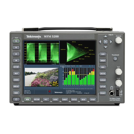
Page 47: フロント・パネル・コントロール
フロント・パネル・コントロール フロント・パネル・コントロール 注: このセクションに記載されているコントロールの一部は、オプションによって 異なります。本製品に搭載されているオプションを表示するには、CONFIG ボタ ンを押します。設定メニューで、Utilities サブメニューを選択してください。View Instruments Options に、本製品に搭載されているオプションが表示されます。 レイアウトと使用方法 次の図にフロント・パネル要素を示し、それに続く表でそれらの各要素につい て説明します。 フロント・パネル コントロール要素またはグルー プ 説明 ビデオ波形を表示します。 PICT ビデオ信号によって生成されるピクチャを表示します。 GAMUT SDI 信号のガマットをチェックする表示。当社独自の 3 つのビューから選択で きます。 VECTOR 色信号のベクトルまたはライトニングのプロットを表示します。 AUDIO オーディオ信号を監視するレベル(メーター)およびフェーズ(プロット)を表示 します。 STATUS 信号のステータスおよび情報を表示します。 WFM5200 Installation and Safety Instructions... - Page 48 タイル表示または全画面表示で、波形の位置を指定するために使用します。オー ディオ・タイルがアクティブなときは、水平ノブでヘッドフォンの音量を調整できます。 警告: 聴覚障害の危険性を避けるため、ヘッドフォンは必ず音声レベルを下げた 状態でヘッドフォンジャックに接続してください。音声レベルとインピーダンスはヘッ ドフォンによって異なります。 Display Select/Thumbnail デフォルト設定ではタイル選択ボタンとなり、本器が 4 タイル・モードのときに、素早 く次のタイルに移動することができます。このボタンで MAIN ボタン・メニューから、 選択された測定表示で、ピクチャのサムネイル表示に設定することもできます。 電源ボタン 電源を投入または遮断します。 HELP オンライン・ヘルプを表示します。 CONFIG 各種設定パラメータ、搭載されているオプション、IP アドレス、システム・アップグ レードなどにアクセスできます。 DISPLAY 波形、目盛、および LCD バックライトの輝度を操作できます。無限パーシスタン ス・モードを選択することもできます。 MAIN タイル表示モード、表示オーバーレイ、マルチ入力モードの有効化、USB ステータ ス、マルチボタン機能(DISPLAY SELECT ボタンをサムネイル表示のオン/オフに 使用できるように設定可能)、およびサムネイルのオン/オフにアクセスします。 WFM5200 Installation and Safety Instructions...
- Page 49 タイル固有の設定:ポップアップ・メニューは、表示されるタイルに固有のパ ラメータをコントロールします。ポップアップ・メニューは、波形の表示モー ドなど、あまり頻繁に変更しないパラメータをコントロールします(波形表示 モードを RGB から YPbPr に変更するなど)。ポップアップ・メニューを表示 するには、対象のボタンを約 2 秒間押し続けます。 機器全体の設定:Configuration メニューのパラメータは、機器全体の設定 です。Configuration メニューは、波形の色やネットワーク・アドレスの設定 など、変更頻度の少ない設定をコントロールします。 コントロールの範囲 コントロールには、機器全体およびすべてのタイルに影響するものと、アクティ ブなタイルにのみ影響するものがあります。一般に、フロント・パネルのボタン またはポップアップ・メニューで設定した制御内容は、アクティブなタイルにの み適用されます(Input ボタンとすべてのオーディオ機能は例外で、これらは 全体に適用されます)。CONFIG メニューで設定した制御内容は、通常、機器 全体に適用されます。 前言 本文档包含以下信息: 有关避免人身伤害,并防止损坏本产品或与本产品连接的任何产品的 安全性预防措施 仪器遵循的 EMC(电磁兼容性)、安全和环境标准 使用本产品的电压、功率和环境要求 安装步骤 开机和关机步骤 前面板和后面板功能 WFM5200 Installation and Safety Instructions...
- Page 50 一个 75 Ω 终接器,用在后部面板连接器上。EXT REF(外部 参考)连接器在使用时需要终接。 WFM50F01 WFM50F01,便携机柜,有手柄、支脚、斜支架和前面板盖。 WFMRACK-NN WFMRACK-NN 容纳两台 WFM8xxx、WFM7xxx 或 WFM6xxx。还带两 个较浅的适配器用于容纳两台 WFM5xxx 或 WFM4000。 WFMRACK-ON WFMRACK-ON 容纳一台较旧的单元(1700 系列、WFM601 或 764)和一台新单元,例如 WFM8xxx、WFM7xxx 或 WFM6xxx。还 带一个较浅的适配器(只能在新的套管中使用)用于 WFM5xxx 或 WFM4000。 电源线 不适用 说明: 参阅此表后面的国际电源线列表,了解仪器中包含的 电源线类型。 WFM5200 Installation and Safety Instructions...
- Page 51 项目 用途 位置 安装和安全性说明(本手册) 提供安全性和符合性信息以及硬件安装说明, 以印刷手册形式提供,也可从 并以此介绍相关安全警告。本手册提供英文、 www.tektronix.com/manuals 日文和简体中文版本。 上获取该文档的电子版本 用户手册 提供操作和应用信息。本手册提供英文版本。 可从产品文档 CD 中以及 www.tektronix.com/manuals 上获取 在线帮助 详细的仪器操作和用户界面帮助。 可从仪器上访问 系统集成技术参考 为系统集成商提供信息,用于在部署这些仪 可从产品文档 CD 中以及 器的地方设计 HD、SD 和 3 Gb/s SDI 视频内 www.tektronix.com/manuals 容系统。 上获取 WFM5200 Installation and Safety Instructions...
- Page 52 技术规格和性能验证技术参考 技术规格和仪器性能检查步骤。 可从产品文档 CD 中以及 www.tektronix.com/manuals 上获取 WFM 和 WVR 系列管理信息数 用于远程控制仪器的 SNMP 命令参考。 可从产品文档 CD 中以及 据库 (MIB) 程序员手册 www.tektronix.com/manuals 上获取 维修手册 提供有关调整、维修和可更换部件的信息。 可 从 www.tektronix.com/manuals 上获取 可 从 发行说明 介绍特定软件版本发行的主要功能和已知限 制。 www.tektronix.com/manuals 上获取 WFM5200 Installation and Safety Instructions...
-
Page 53: 常规安全概要
常规安全概要 详细阅读下列安全性预防措施,以避免人身伤害,并防止损坏本产品或与 本产品连接的任何产品。 为避免可能的危险,请务必按照规定使用本产品。 只有合格人员才能执行维修程序。 避免火灾或人身伤害 使用合适的电源线: 只使用本产品专用并经所在国家/地区认证的电源线。 将产品接地: 本产品通过电源线的接地导线接地。为避免电击,必须将接 地导线与大地相连。在对本产品的输入端或输出端进行连接之前,请务必 将本产品正确接地。 遵循所有终端额定值: 为避免火灾或电击危险,请遵循产品上所有的额定 值和标记说明。在连接产品之前,请先查看产品手册,了解额定值的详细 信息。 对任何终端(包括公共终端)施加的电压不要超过该终端的最大额定值。 断开电源: 电源线可以使产品断开电源。不要阻挡电源线;用户必须能随 时触及电源线。 切勿开盖操作: 外盖或面板打开时请勿操作本产品。 怀疑产品出现故障时,请勿进行操作: 如果怀疑本产品已损坏,请让合格 的维修人员进行检查。 远离裸露电路: 电源接通后请勿接触外露的接头和元件。 使用合适的交流适配器: 只能使用为本产品指定的交流适配器。 请勿在潮湿环境下操作: 请勿在易燃易爆的气体中操作: 请保持产品表面清洁干燥: 保持适当的通风: 有关如何安装产品使其保持适当通风的详细信息,请参 阅手册中的安装说明。 WFM5200 Installation and Safety Instructions... - Page 54 常规安全概要 本手册中的术语 本手册中可能使用以下术语: 警告: “警告”声明指出可能会造成人身伤害或危及生命安全的情况或 操作。 注意: “注意”声明指出可能对本产品或其他财产造成损坏的情况或操 作。 产品上的符号和术语 产品上可能出现以下术语: DANGER(危险)表示您看到该标记时可直接导致人身伤害的危险。 WARNING(警告)表示您看到该标记时不会直接导致人身伤害的危险。 CAUTION(注意)表示可能会对本产品或其他财产带来的危险。 产品上可能出现以下符号: WFM5200 Installation and Safety Instructions...
-
Page 55: 符合性信息
EN 55103-2:1996 附件 A 放射性磁场的抗扰性 EN 55103-2:1996 附件 B 平衡端口共模抗扰性 为确保符合上面列出的 EMC 标准,应使用高质量的屏蔽接口电缆。 浪涌电流:8 A 峰值。 EN 61000-3-2:2006: 交流电源线谐波辐射 EN 61000-3-3:1995: 电压变化、波动和闪变 欧洲联系方式: Tektronix UK, Ltd. Western Peninsula Western Road Bracknell, RG12 1RF, United Kingdom(英国) WFM5200 Installation and Safety Instructions... -
Page 56: 环境注意事项
定 , CR 锂 电 池 被 归 类 为 高 氯 酸 盐 材 料 , 需 要 特 殊 处 理 。 详 情 参 见 www.dtsc.ca.gov/hazardouswaste/perchlorate。 有害物质限制 本 产 品 属 于 工 业 监 视 和 控 制 仪 器 , 并 且 无 须 符 合 RoHS Directive 2011/65/EU 重订版的物质限制要求(截至 2017 年 7 月 22 日)。 WFM5200 Installation and Safety Instructions... -
Page 57: 操作要求
操作要求 操作要求 本部分提供为安全正确地操作产品而需要了解的技术规格。有关其他信 息,请参阅完整的产品技术规格。 电源额定值 电源要求 电源连接器 说明: 如果订购电源线,则会附带有磁芯。请按照发运时附带的说明安 装磁芯。 仪器通过外部交流适配器工作,对电源要求如下: 单相电源,其中有一根载流导线接地或近地(中性导线)。 电源频率必须为 50 或 60 Hz,工作电压范围必须为 100 到 240 VAC, 且为连续。 警告: 为减少起火和电击风险,请确保市电电源的电压波动不超过工作 电压范围的 10%。 两条载流导线的接地均带电(例如多相位系统中的相间电压)的系统 不建议用作电源。 说明: 只有线路导线装有保险丝以提供过流保护。保险丝为内置,不可 由用户更换。请勿尝试更换保险丝。如果您怀疑保险丝熔断了,请将该单 元送回授权维修中心进行维修。 WFM5200 Installation and Safety Instructions... -
Page 58: 环境额定值
为确保通风良好,仪器两侧和后侧必须至少具有 2 英寸(5 厘米)的间隙, 可选套管) 仪器顶部必须至少具有 1/2 英寸(1.3 厘米)的间隙。 便携机柜 仅应使用 Tektronix 便携机柜 WFMF02,确保本仪器具有良好的通风条件。使 用便携机柜时,适用的最小间隙与使用裸仪器时相同。 机架机柜 对于本仪器仅使用 WFMRACK-NN 或 WFMRACK-ON 机架安装适配器。为确保通风 良好,在机架壁为实心的封闭机架中安装机架适配器时,机架适配器框架两侧 和机架侧壁之间必须至少具有 2 英寸(5 厘米)的间隙,机架适配器框架后 侧和机架后壁之间必须至少具有 3 英寸(7.6 厘米)的间隙,机架适配器顶 部和另一个机架适配器或另一个安装的仪器之间必须至少具有 1/2 英寸(1.3 厘米)的间隙。到达侧通风口的机架进气不得超过 40℃。 WFM5200 Installation and Safety Instructions... -
Page 59: 物理技术规格
操作要求 物理技术规格 表 9: 物理特性 特性 标准 尺寸 高度 5.25 英寸(133.4 毫米) 宽度 8.5 英寸(215.9 毫米) 厚度 4.75 英寸(120.7 毫米) 重量 净重 3.3 磅(1.5 千克) 装运 12 磅(5.4 千克),近似,不包括选件和附件 清洁 不需要为了安全操作仪器而对仪器进行清洁。但是如果要对仪器外部执行 日常清洁,请参阅仪器附带的产品文档 CD 上的用户手册。 WFM5200 Installation and Safety Instructions... -
Page 60: 后面板连接器
后面板连接器 后面板连接器 后面板如下图所示。SDI 输入为水平排列,外部参考连接器为垂直排列。 后面板 输入和输出连接器 视频连接器 SDI 输入为自终接输入。 输入 连接器 参考环路。同步输入。输入信号可以是模拟黑色突发 脉冲、模拟复合视频或 HD 的模拟三电平。需要终端。 说明: 参考输入是无源环路输入,所以需要外部终 接。 SDI 1A。数字 A 分量串行数字输入。 SDI 1B。数字 B 分量串行数字输入。 SDI 2A。数字 A 分量串行数字输入。 SDI 2B。数字 B 分量串行数字输入。 WFM5200 Installation and Safety Instructions... - Page 61 EXT DISPLAY(外部显 这是外部显示监视器输出。显示分辨率为 1024 x 768。此输出直接支持 示)连接器针脚的分配 DVI 监视器,并可通过使用 DVI 到 VGA 适配器来支持模拟 PC (RGB) 监 视器。EXT DISPLAY(外部显示)连接器是一个 DVI-I 插座连接器。 EXT DISPLAY(外部显示)连接器 REMOTE(远程)连接 REMOTE(远程)连接器接口使用接地屏蔽盒进行远程控制,并使用接地屏 器针脚的分配 蔽盒在发生告警时向外部设备发出指示。LTC 的输入通过 REMOTE(远程) 连接器进行。REMOTE(远程)连接器是一个 15 针脚 D 型插座连接器 说明: 有关预置调用的更多信息,参阅仪器附带的产品文档光盘上的用 户手册。 WFM5200 Installation and Safety Instructions...
- Page 62 XX0110 预置 6 XX0101 预置 5 XX0100 预置 4 XX0011 预置 3 XX0010 预置 2 XX0001 预置 1 XX0000 未使用 101111 预置 5 011111 预置 6 以太网连接器 本仪器提供了一个 10/100/1000 BaseT 以太网接口。以太网连接器是标准 的 RJ-45 连接器。 以太网连接器 WFM5200 Installation and Safety Instructions...
-
Page 63: 基本安装步骤
基本安装步骤 基本安装步骤 仪器出厂时处于全封闭金属机箱中。可在提供的机箱中操作仪器,或将机 箱安装在符合要求的便携机柜或机架适配器上。 要将仪器安装在机柜或机架中,请按照可选附件箱随附的说明进行操作, 可选附件箱适用于各种安装。有关冷却和间隙的要求,另请参阅“环境额 环境额定值 定值”部分。 ( 见第52页, 注意: 请勿将仪器安装在“附件”表所列范围之外的任何机柜中;否则 将会损坏仪器和机柜。 如果需要将仪器安装在控制台之类的自定义装置中,务必确保有良好的通 风条件,并确保到达侧通风口的进气不超过 40℃,请勿阻塞或限制通风 孔。有关冷却和间隙的要求,请参阅“环境额定值”部分。 ( 见第52页, 环境额定值 在自定义装置中安装时,请遵守适用于机架适配器的间隙要求。 注意: 为避免火灾风险,必须保持良好的通风条件。如无法为仪器提供 足够的通风,可能造成仪器关机。恶劣的通风条件包括将仪器放置在任何 缺少通风系统的狭小封闭的空间(如橱柜)内。如果限制或堵塞了气流而 仪器未关机,仪器可能遭到永久性损坏,并且会增加火灾风险。 WFM5200 Installation and Safety Instructions... -
Page 64: 在视频系统中安装
基本安装步骤 在视频系统中安装 在需要串行数字系统监视的分布式系统中,本仪器几乎可在任何位置工 作。 监视串行接收机的视频 将一个或多个进入串行信号转接至仪器后面板的 SDI 输入上。 位流 说明: 有关允许的最大电缆长度,请参阅产品文档 CD 上的《技术规格 和性能验证》手册。 WFM5200 Installation and Safety Instructions... - Page 65 基本安装步骤 监视串行数字视频流中 将输入串行信号输入到仪器的一个 SDI 输入上。 的嵌入式音频信号 监视外部参考信号 将进入的参考信号转接到仪器的一个 REF 输入上,用 75 Ω 终接器终接 其他连接器以保证闭环。 WFM5200 Installation and Safety Instructions...
- Page 66 如果仪器安装用来监视运行链路,则目标接收机和连接电缆将充当终端。 这种监视连接检查整个通路的性能。仪器的回波损耗非常高,因此在大多 数情况下目标接收机都设定系统回波损耗。 如果仪器被置于链路的末端,则必须在环通回路参考连接器的一端安装一 个 BNC 终端。该终端必须为 75 Ω 且为直流耦合(良好的回波损耗延伸 至直流)。部件号为 011-0163-00 的 Tektronix 部件便是 EXT REF 连接 器的合适终端,它是 75 Ω 的线端终端。 BNC 中心针脚的兼容性 视频设备的大部分 BNC 连接器,不管是 50 Ω 的还是 75 Ω 的,都使用 50 Ω 标准中心针。有些实验室用的 75 Ω BNC 连接器使用更小直径的中...
-
Page 67: 开机和关机步骤
本仪器通过外部交流适配器工作,要求线路频率为 50 或 60 Hz,电压范 国际电源线 围为 100-240 伏,除电源线外无需其他配置。( 见第45页, 典型功率为 27 瓦特。有关电源和环境要求的更多信息,参见产品文档光 盘上的《WFM5200 技术规格和性能验证技术参考》。 电 如果用电池作为电源,请阅读本手册前面的电池信息。 ( 见第52页, 池电源 开机 1. 将附带的电源线接到后面板上的电源连接器上。如果使用电池,请按 照电池附带的安装指南来连接电池。 2. 按仪器前面板上的电源按钮,仪器将会打开。 说明: 前面板上的待机按钮不会断开市电电源。仅产品后面的电源线可 以断开市电电源。 仪器工作时,确保可随时够到电源线。 关机 1. 按仪器前面板上的电源按钮关闭仪器。 2. 如果要完全切断电源,请从仪器后面板断开电源线。 WFM5200 Installation and Safety Instructions... -
Page 68: 前面板控件
显示视频信号生成的图像 GAMUT(色域) 用于在检查 SDI 信号的色域时进行显示;可选择显示三种 Tektronix 专有视图 VECTOR(矢量) 显示彩色信号的 Vector(矢量)或 Lightning(闪电)绘图 AUDIO(音频) 电平(仪表)和相位(绘图)的可选显示,用于监视音频信号。 STATUS(状态) 用不同显示来表示信号状态和信息 OTHER(其他) LTC 显示:检查 LTC 幅度和噪声,并验证 LTC 是否锁定到视频。外部参考波 形显示:查看外部参考输入的波形。诊断监视器:查看诊断信息。 MEAS(测量) 用于简化定时校正的 Tektronix 专有显示。包括 Timing Measure(定时测 量)、Data List(数据列表)、Bowtie(蝴蝶结)和 ANC Data(ANC 数 据)显示。 WFM5200 Installation and Safety Instructions... - Page 69 用于在区域或全屏显示时定位波形。当 Audio(音频)区域活动时,使用 旋钮 Horz(水平)旋钮可调节耳机音量 警告: 为避免听力受损,将耳机插入耳机插孔前,请务必先将音量调低。不 同耳机的音量和阻抗可能会不同。 Display Select(显示选择) 默认设置将此按钮设定为区域选择按钮,在仪器处于四区域模式时可快速地在 /Thumbnail(缩略图) 区域之间进行移动。也可从 MAIN(主要)按钮菜单中设置此按钮,在选定的 测量显示中显示图片的缩略图视图。 电源按钮 按下可打开或关闭电源。 HELP(帮助) 用于显示在线帮助 CONFIG(配置) 用于访问不同的可配置参数、安装的选件、IP 地址、系统升级等 DISPLAY(显示) 用于访问波形、刻度和 LCD 背光亮度。同时也可访问 Infinite Persistence (无限余晖)模式。 MAIN(主) 设置区域显示模式,显示叠加、多输入模式启用、USB 状态、多按钮功能 (可配置 Display Select(显示选择)按钮以打开或关闭缩略图视图)以 及缩略图开/关。 WFM5200 Installation and Safety Instructions...
- Page 70 前面板控件 三种控制级别 可在三个级别上控制仪器: 频繁更改的设置。前面板按钮控制经常更改的参数,如每个区域中显 示的测量。旋钮用于调整级别和进行选择。 区域特定的设置。弹出菜单控制特定于所在显示区域的参数。弹出菜 单控制不太经常更改的参数,例如波形显示模式(例如,将波形显示 模式从 RGB 更改为 YPbPr)。要显示一个弹出菜单,请按住所需的按 钮大约两秒钟。 仪器范围的设置。Configuration(配置)菜单中的参数为整个仪器 范围的设置。配置菜单控制只是偶尔更改的设置,比如更改波形颜色 或设置网络地址。 控件范围 有些控件适用于全局并影响所有区域,而有些控件只影响当前区域。一 般来说,如果一个控件是由前面板按钮或弹出菜单配置的,则它特定于区 域。(Input(输入)按钮和所有音频功能除外,它们适用于全局。)如 果某个控件通过 CONFIG(配置)菜单配置,则相关选择通常适用于全局。 WFM5200 Installation and Safety Instructions...
Need help?
Do you have a question about the WFM5200 and is the answer not in the manual?
Questions and answers