Table of Contents
Advertisement
Quick Links
Advertisement
Table of Contents
Troubleshooting

Related Manuals for Tektronix WFM5250


Summary of Contents for Tektronix WFM5250
- Page 1 WFM5250 Waveform Monitor Service Manual *P077080000* 077-0800-00...
- Page 3 WFM5250 Waveform Monitor Service Manual Warning The servicing instructions are for use by qualified personnel only. To avoid personal injury, do not perform any servicing unless you are qualified to do so. Refer to all safety summaries prior to performing service.
- Page 4 Copyright © Tektronix. All rights reserved. Licensed software products are owned by Tektronix or its subsidiaries or suppliers, and are protected by national copyright laws and international treaty provisions. Tektronix products are covered by U.S. and foreign patents, issued and pending. Information in this publication supersedes that in all previously published material.
- Page 5 Tektronix, with shipping charges prepaid. Tektronix shall pay for the return of the product to Customer if the shipment is to a location within the country in which the Tektronix service center is located. Customer shall be responsible for paying all shipping charges, duties, taxes, and any other charges for products returned to any other locations.
-
Page 7: Table Of Contents
Preventing ESD ....................Inspection and Cleaning..................Troubleshooting....................Getting Started ....................Symptoms and Causes ..................Detailed Troubleshooting Procedures ..............Removal and Replacement Procedures ................. Preparation..................... Module Removal....................Repackaging Instructions ..................Packaging ...................... Shipping to the Service Center ................WFM5250 Waveform Monitor Service Manual... - Page 8 Table of Contents Replaceable Parts ....................Parts Ordering Information .................. Using the Replaceable Parts Lists................WFM5250 Waveform Monitor Service Manual...
- Page 9 List of Figures Figure 1: Instrument block diagram ................Figure 2: Video I/O board ..................Figure 3: WFM5250 rear panel .................. Figure 4: XLR connector ground clip ................Figure 5: Screws that attach fan bracket to main chassis ............. Figure 6: Fan screw placement ..................
- Page 10 Table 2: Internal inspection checklist ................Table 3: Required test equipment................Table 4: Symptoms and causes .................. Table 5: Video I/O board basic supplies ................ Table 6: Tools required for module removal ..............Table 7: Replaceable parts list ................... WFM5250 Waveform Monitor Service Manual...
-
Page 11: Important Safety Information
To avoid electric shock, the grounding conductor must be connected to earth ground. Before making connections to the input or output terminals of the product, make sure that the product is properly grounded. WFM5250 Waveform Monitor Service Manual... - Page 12 Recharge batteries properly. Recharge batteries for the recommended charge cycle only. Do not operate in wet/damp conditions. Be aware that condensation may occur if a unit is moved from a cold to a warm environment. WFM5250 Waveform Monitor Service Manual...
-
Page 13: Service Safety Summary
Provide a safe working environment. Always place the product in a location convenient for viewing the display and indicators. Use only the Tektronix rackmount hardware specified for this product. Service safety summary The Service safety summary section contains additional information required to safely perform service on the product. -
Page 14: Symbols And Terms On The Product
find out the nature of the potential hazards and any actions which have to be taken to avoid them. (This symbol may also be used to refer the user to ratings in the manual.) The following symbol(s) may appear on the product: viii WFM5250 Waveform Monitor Service Manual... -
Page 15: Preface
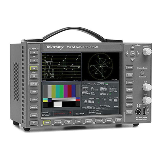
Preface This manual supports servicing to the module level of the WFM5250 Waveform Monitor, which processes video signals for display on an internal XGA LCD. The instrument is used as a monitor in broadcasting, production, and post-production environments. This manual explains how to troubleshoot and service the instrument to the module level. - Page 16 Procedure for checking performance and Product Documentation CD Verification Technical Reference list of specifications www.tektronix.com/downloads System Integration Technical Reference Provides information for system Product Documentation CD integrators who are designing systems www.tektronix.com/downloads where this product will be deployed. WFM5250 Waveform Monitor Service Manual...
-
Page 17: Introduction
The WFM5250 Waveform Monitor provides a powerful monitoring solution for broadcast, production, and post-production environments. Service Strategy These products are repaired to the module level at selected Tektronix service centers. Repair includes functional verification of the product. Component level repair by the customer is not supported. -
Page 18: Product Upgrade
Product Upgrade Software upgrades are available for all products as free software downloads from the Tektronix Web site. The user manual includes instructions for updating product software. To purchase additional features and capabilities for your instrument, contact Tektronix for more information on purchasable options. -
Page 19: Theory Of Operation
Theory of Operation The WFM5250 includes extensive standard capabilities, which can be augmented by adding various options. This instrument uses an internal DVI-I monitor for the display, and has an output to drive an external monitor with the same display. It also has outputs to drive a serial digital picture monitor. -
Page 20: Figure 1: Instrument Block Diagram
Theory of Operation Figure 1: Instrument block diagram WFM5250 Waveform Monitor Service Manual... -
Page 21: Video I/O Board
For any given frame, the intensity map is built up in one memory chip and read out of the other. The functions swap on the next field. WFM5250 Waveform Monitor Service Manual... -
Page 22: Cpu Board
HDMI audio is extracted from the HDMI stream by the HDMI input IC. It is then output via an I2S interface to the FPGA board, where it enters the DSP FPGA. Once on the FPGA board, the audio is processed in a manner similar to the SDI audio. WFM5250 Waveform Monitor Service Manual... -
Page 23: Fan Control
A latching relay controls standby mode. The nominal 12 V DC input powers 5 V and 3.3 V supplies. All three voltages are distributed to the CPU and FPGA boards to power circuits as well as lower voltage local regulators. WFM5250 Waveform Monitor Service Manual... - Page 24 Theory of Operation WFM5250 Waveform Monitor Service Manual...
-
Page 25: General Maintenance
Service static-sensitive modules only at a static-free work station. 4. Nothing capable of generating or holding a static charge should be allowed on the work station surface. 5. Handle circuit boards by the edges when possible. WFM5250 Waveform Monitor Service Manual... - Page 26 General Maintenance 6. Do not slide the circuit boards over any surface. 7. Avoid handling circuit boards in areas that have a floor or work-surface covering capable of generating a static charge. WFM5250 Waveform Monitor Service Manual...
-
Page 27: Inspection And Cleaning
4. Gain access to the parts to be cleaned by removing easily accessible shields and panels. 5. Spray wash dirty parts with the isopropyl alcohol and wait 60 seconds for the majority of the alcohol to evaporate. 6. Dry all parts with low-pressure, deionized air. WFM5250 Waveform Monitor Service Manual... -
Page 28: Table 1: External Inspection Checklist
Use a glass cleaner to clean the LCD. For the rest of the instrument, use a 75% isopropyl alcohol solution as a cleaner and rinse with deionized water. Before using any other type of cleaner, consult your Tektronix Service Center or representative. -
Page 29: Table 2: Internal Inspection Checklist
Wiring and Loose plugs or connectors. Burned, Firmly seat connectors. Repair cables broken, or frayed wiring. or replace modules with defective wires or cables. Chassis Dents, deformations, and damaged Straighten, repair, or replace hardware. defective hardware. WFM5250 Waveform Monitor Service Manual... -
Page 30: Troubleshooting
find your problem in the table, or if no specific problem was reported by the user, follow the steps in the Unknown Problem section of the table. The WFM5250 Waveform Monitor is highly configurable, and its behavior is sometimes complex. Before troubleshooting in-depth, verify that: The installed options are as expected. -
Page 31: Table 3: Required Test Equipment
Table 3: Required test equipment Test equipment Requirements Example SDI serial digital video test 1080p 59.94 3 Gb/s signals required: Tektronix TG700 with an HD3G7 module generator with embedded (Embedded audio needed for audio 100% color bars audio. Instruments with option options) 3G require a 3 Gb/s SDI source. -
Page 32: Symptoms And Causes
USB bad Replace CPU board Ethernet bad Replace CPU board Fans bad Perform Fan checks Headphones bad, audio bars okay Replace CPU board Reference or LTC waveform bad Check Reference I/O cable Replace Reference I/O board WFM5250 Waveform Monitor Service Manual... - Page 33 Perform the incoming inspection tests. This will exercise a majority of the functions in the unit and includes the Advanced Diagnostics. Some parts of the test may not be necessary for all problem areas. WFM5250 Waveform Monitor Service Manual...
-
Page 34: Detailed Troubleshooting Procedures
Video I/O board continuity: Resistance from J2 pin 211 to switch S1 pins nearest the edge of the board should be less than 10 ohms. Replace any cable or board that fails the resistance checks. WFM5250 Waveform Monitor Service Manual... -
Page 35: Table 5: Video I/O Board Basic Supplies
Video I/O board. If voltages are within the allowed range, replace the CPU board. Table 5: Video I/O board basic supplies Nominal (+V) Allowed range (+V) +12V 11 to 17 4.85 to 5.15 +3.3V 3.2 to 3.4 WFM5250 Waveform Monitor Service Manual... -
Page 36: Figure 2: Video I/O Board
Troubleshooting Figure 2: Video I/O board WFM5250 Waveform Monitor Service Manual... - Page 37 4. Display backlight cable at CPU board J5 (remove Video I/O board to gain access, then reinstall Video I/O board) For the next two steps, test by pressing Video I/O board switch S1 instead of the (disconnected) front panel power button. WFM5250 Waveform Monitor Service Manual...
- Page 38 FPGA board. Replace the FPGA board. If the power up behavior differs from that described above, perform the Basic Power Supply Fault Checks to further isolate the faulty module. WFM5250 Waveform Monitor Service Manual...
- Page 39 R201, R203, R202, and R204 on the CPU board, and use the oscilloscope to look for a 3.3 V square wave on the tachometer feedback line. If resistors are intact but there is no signal on the tachometer line, replace the affected fan. WFM5250 Waveform Monitor Service Manual...
- Page 40 2. If the buttons are not lit, check the 10 pin cable from the keypad to the main board J21. If the cable is connected and good, then replace the front panel assembly. WFM5250 Waveform Monitor Service Manual...
-
Page 41: Removal And Replacement Procedures
NOTE. Read Equipment Required for a list of the tools needed to remove and install modules in this instrument. (See Table 6 on page 26.) Read the cleaning procedure before disassembling the instrument for cleaning. WFM5250 Waveform Monitor Service Manual... -
Page 42: Table 6: Tools Required For Module Removal
MA-800G Soldering Used for removing the front panel trim Standard tool Aid (spudger) Soldering iron (15 W) Used for replacing main board fuses Standard tool Long nose pliers Used to compress connector lock tabs Standard tool WFM5250 Waveform Monitor Service Manual... -
Page 43: Module Removal
2. Remove the three pan-head 32 X 0.250 T15 screws from the back of the instrument. When reinstalling, tighten these screws to 0.9 N-M (8 in/lb). Figure 3: WFM5250 rear panel 3. Remove the nine flat-head 32 X 0.250 T10 screws on the front edge of the top cover (three on the top and two on each side and the bottom). -
Page 44: Figure 4: Xlr Connector Ground Clip
Reference I/O board still attached, slightly away from the main chassis. When reassembling, slightly push out the sides of the main chassis until the alignment tabs engage the slots in the rear panel. Figure 4: XLR connector ground clip WFM5250 Waveform Monitor Service Manual... - Page 45 3. Continue disassembling the instrument. You first must remove the FPGA board and the Video I/O board in order to access the fan drive connectors, which are located below these boards on the CPU board. WFM5250 Waveform Monitor Service Manual...
-
Page 46: Figure 5: Screws That Attach Fan Bracket To Main Chassis
Video I/O board from the CPU board. When reinstalling, make sure that these connectors are aligned correctly before pushing the Video I/O board down onto the CPU board. 3. Place the Video I/O board on a static-free work surface. WFM5250 Waveform Monitor Service Manual... -
Page 47: Figure 6: Fan Screw Placement
J5 on the CPU board. Pull these plugs straight away from their connectors, to prevent damage. 4. Move the CPU board away from the main chassis and place it on the static-free work surface. WFM5250 Waveform Monitor Service Manual... -
Page 48: Figure 7: Cpu Board Screw And Spacer Posts
Removal and Replacement Procedures Figure 7: CPU board screw and spacer posts WFM5250 Waveform Monitor Service Manual... -
Page 49: Figure 8: Correct Spring Clip Position
0.687L 0.188 hex spacer posts that secure the front panel board to the bezel. 5. Lift the front panel board away from the bezel. 6. Remove the elastomer mat from the bezel. Figure 8: Correct spring clip position WFM5250 Waveform Monitor Service Manual... -
Page 50: Figure 9: Screws That Attach Lcd Module To Main Chassis
3. The LCD module should not be further disassembled. The entire module, including the LCD, board and cables, can be replaced by ordering part number 119-7439-01. Figure 9: Screws that attach LCD module to main chassis WFM5250 Waveform Monitor Service Manual... -
Page 51: Repackaging Instructions
Type and serial number of the instrument. Reason for returning. A complete description of the service required. Mark the address of the Tektronix Service Center and the return address on the shipping carton in two prominent locations. WFM5250 Waveform Monitor Service Manual... - Page 52 Repackaging Instructions WFM5250 Waveform Monitor Service Manual...
- Page 53 For more information about the module exchange program, call 1-800-833-9200. Outside North America, contact a Tektronix sales office or distributor; see the Tektronix Web site for a list of offices: www.tektronix.com. Module Repair and Return. You may ship your module to us for repair, after which we will return it to you.
- Page 54 Items in this section are referenced by figure and index numbers to the illustrations that follow. number Orderable modules show the figure number without an index number. Tektronix part Use this part number when ordering replacement parts from Tektronix. number 3 and 4 Serial number Column three indicates the serial number at which the part was first effective.
-
Page 55: Table 7: Replaceable Parts List
SWITCH, PUSH: SPST, TACT, 50MA, 50V, MOMENTARY, SILVER CONTACTS (Reset button, on bottom of CPU board) 146-0109-00 BATTERY, DRY: 3.0V, LITHIUM MANGANESE DIOXIDE, 210MAH, 20 X 3.22MM COIN CELL WITH SOLDER TABS, CR2032-1HF1 863-0851-00 CIRCUIT BD ASSY: CPU WFM5250 Waveform Monitor Service Manual... - Page 56 214-4748-00 HEAT SINK: IC, PGA 11X11/MQUAD/27MM BGA; 1.1 X 1.1 X 0.25 H, PIN FIN, AL, BLACK ANODIZE 863-0884-00 CIRCUIT BD ASSY: FPGA 174-5921-00 CABLE ASSY: FPGA TO REF I/O 40 PIN 220-0271-01 SPANNER NUT WFM5250 Waveform Monitor Service Manual...
-
Page 57: Figure 10: Wfm5250 Exploded View
Replaceable Parts Figure 10: WFM5250 Exploded View WFM5250 Waveform Monitor Service Manual...
Need help?
Do you have a question about the WFM5250 and is the answer not in the manual?
Questions and answers