Norac UC5 Installation Manual
Spray height controller summers (main lift & enhanced stability)
Hide thumbs
Also See for UC5:
- Operator's manual (68 pages) ,
- Installation manual (50 pages) ,
- Instruction manual (35 pages)

Subscribe to Our Youtube Channel
Related Manuals for Norac UC5


Summary of Contents for Norac UC5
- Page 1 Spray Height Controller Summers (Main Lift & Enhanced Stability) Installation Manual SM03-4B...
- Page 2 Reorder P/N: UC5-SM03-4B-INST Rev C (Summers Main Lift & Enhance Stability Option – 44962D) NOTICE: NORAC Systems International Inc. reserves the right to improve products and their specifications without notice and without the requirement to update products sold previously. Every effort has been made to ensure the accuracy of the information...
-
Page 3: Table Of Contents
Contents Introduction .....................1 Kit Parts ......................2 Hydraulic Installation ..................5 Roll Sensor Installation ..................7 Electrical Installation ..................9 Software Setup ..................... 11 Cable Drawings .................... 12... -
Page 4: Introduction
1 Introduction Congratulations on your purchase of the NORAC UC5 Spray Height Controller. This system is manufactured with top quality components and is engineered using the latest technology to provide operating reliability unmatched for years to come. When properly used the system can provide protection from sprayer boom damage, improve sprayer efficiency, and ensure chemicals are applied correctly. -
Page 5: Kit Parts
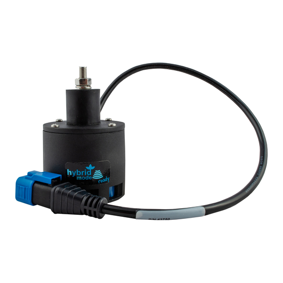
2 Kit Parts Hydraulic Plumbing Figure 1: SM03 Hydraulic Plumbing... - Page 6 The following tables list the Summers main lift and enhanced stability kit (SM03) specific parts of the NORAC UC5 system. This kit is to be used when installing the proportional main lift option with existing Summers installations that have a valve block that was purchased after December of 2010.
- Page 7 SIZE FACE P - PIPE The use of dielectric grease is not recommended on any NORAC electrical connections. To ensure all stainless steel hardware does not gall or seize apply a light coating of the supplied Permatex Anti-seize grease to all threaded parts upon installation.
-
Page 8: Hydraulic Installation
Hydraulic pressure will exist on the main lift circuit unless the main lift is all the way down. Component failure due to oil contamination is not covered under the NORAC UC5 system warranty. It is recommended that a qualified technician perform the hydraulic installation. - Page 9 8. Install the 6MB 6MJ fitting (F04) into the “B” port of the expansion block. 9. Install the 6MBP plug (F03) into the “A” port of the expansion block. 10. If the valve block is not already installed on the sprayer, install it as outlined in the UC5 Spray Height Control installation manual.
-
Page 10: Roll Sensor Installation
4 Roll Sensor Installation All roll sensors must be part number 43741. If the previously installed roll sensors are part number 43740, they must be replaced by 43741 before proceeding with this installation. 1. Securely mount the roll sensor to the included roll sensor bracket using the #6 machine screw and nylon lock-nuts. - Page 11 3. The roll sensor is to be mounted onto the chassis as shown in Figure 5. Ensure the roll sensor is relatively level when chassis is level. Figure 5: Chassis Roll Sensor Mounting 4. Ensure that the chassis roll sensor (Figure 5) has the highest serial number and that the boom frame roll sensor (previously installed) has the lowest serial number (Figure 6).
-
Page 12: Electrical Installation
2. Remove the plugs installed in positions 5 and 6. 3. Connect the 2 pin connector on cables C10 into positions 5 and 6 on the valve module. 4. Connect the other end of cables C10 to the 2 pin connectors on the NORAC expansion block (V01). - Page 13 Figure 8: Electrical Connections Only the components shown in black are included in this kit.
-
Page 14: Software Setup
3. Turn on the power for the display terminal using the switch on the side. 4. Refer to the UC5 Spray Height Control Operator’s Manual to run an automatic install with the “Summers Main Lift Option” type selected. -
Page 15: Cable Drawings
7 Cable Drawings ITEM C10: 43230-04 – CABLE UC5 VALVE DT TO DT ITEM C03: 43210-01 - CABLE UC5 NETWORK 18 AWG - 1M... - Page 16 ITEM C04: 43210-03 - CABLE UC5 NETWORK 18 AWG - 3M...
- Page 17 Canada NORAC Systems International Inc. Phone: (+1) 306 664 6711 Toll Free: 1 800 667 3921 Shipping Address: 3702 Kinnear Place Saskatoon, SK S7P 0A6 United States NORAC, Inc. Phone: (+1) 952 224 4142 Toll Free: 1 866 306 6722...
Need help?
Do you have a question about the UC5 and is the answer not in the manual?
Questions and answers