Norac UC5 Installation Manual
Spray height control system.
enhanced stability option
Hide thumbs
Also See for UC5:
- Operator's manual (68 pages) ,
- Installation manual (50 pages) ,
- Instruction manual (35 pages)
Advertisement
Quick Links
Advertisement

Related Manuals for Norac UC5


Summary of Contents for Norac UC5
- Page 1 Enhanced Stability Option Installation Manual...
- Page 2 Reorder P/N: 5468BC-INST Rev H (UC5 Enhanced Stability Option) NOTICE: NORAC Systems International Inc. reserves the right to improve products and their specifications without notice and without the requirement to update products sold previously. Every effort has been made to ensure the accuracy of the information...
-
Page 3: Table Of Contents
Contents Introduction ....................... 1 Kit Parts ........................2 Technical Specifications .................... 3 Roll Sensor Installation ..................... 4 Electrical Installation ....................5 Software Setup ......................6 Cable Drawings ......................7 ... -
Page 4: Introduction
1 Introduction Congratulations on your purchase of the NORAC UC5 Spray Height Control System. This system is manufactured with top quality components and is engineered using the latest technology to provide operating reliability unmatched for years to come. The enhanced stability option is designed to improve performance on booms that have multiple pivot geometries, or problematic pivot behavior. -
Page 5: Kit Parts
UC5 NETWORK COUPLER 3-WAY Cable C04 may be substituted with part number 43210-03, which is a direct replacement. The use of dielectric grease is not recommended on any NORAC electrical connections. To ensure all stainless steel hardware does not gall or seize apply a light coating of the supplied Permatex Anti-seize grease to all threaded parts upon installation. -
Page 6: Technical Specifications
3 Technical Specifications CAN ICES-3(A)/NMB-3(A) This device complies with part 15 of the FCC Rules. Operation is subject to the following two conditions: (1) This device may not cause harmful interference, and (2) this device must accept any interference received, including interference that may cause undesired operation. This equipment has been tested and found to comply with the limits for a Class A digital device, pursuant to part 15 of the FCC Rules. -
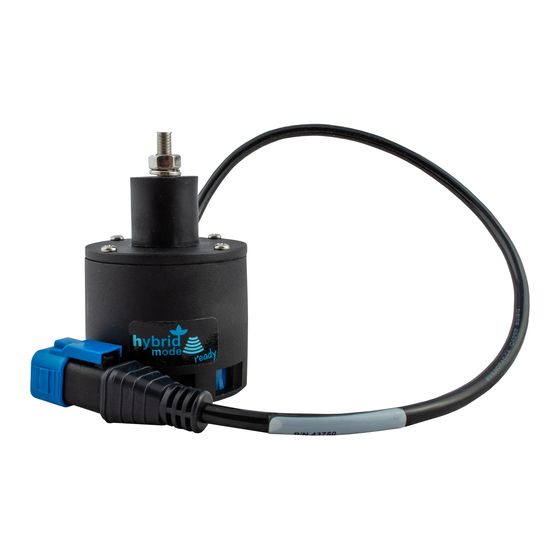
Page 7: Roll Sensor Installation
4 Roll Sensor Installation 1. Determine the location where the Reference Frame roll sensor will be mounted. It must be mounted on the sprayer chassis on a non-moving part. 2. Securely mount the roll sensor to the included roll sensor bracket using the #6 machine screw and nylon lock-nuts. -
Page 8: Electrical Installation
5 Electrical Installation 1. Remove the existing cable C03 from the existing input module (E03). 2. Connect one end of cable C03 to the existing input module (E03) and the other end to the 3-way coupler (E10). 3. Connect existing cable C03 to the third connector on the 3-way coupler (E10). 4. -
Page 9: Software Setup
6 Software Setup 1. Turn on the power for the display terminal using the switch on the side. 2. It is now necessary to perform an Automatic Setup. Refer to the UC5 Operator Manual for instructions how to do this. -
Page 10: Cable Drawings
7 Cable Drawings ITEM C03: 43220-01 - CABLE UC5 NETWORK 14 AWG - 1M ITEM C04: 43220-03 - CABLE UC5 NETWORK 14 AWG - 3M... - Page 11 Canada NORAC Systems International Inc. Phone: (+1) 306 664 6711 Toll Free: 1 800 667 3921 Shipping Address: 3702 Kinnear Place Saskatoon, SK S7P 0A6 United States NORAC, Inc. Phone: (+1) 952 224 4142 Toll Free: 1 866 306 6722...
Need help?
Do you have a question about the UC5 and is the answer not in the manual?
Questions and answers