Norac UC5 Installation Manual
Spray height control system
Hide thumbs
Also See for UC5:
- Operator's manual (68 pages) ,
- Installation manual (50 pages) ,
- Instruction manual (35 pages)
Table of Contents
Advertisement
Quick Links
Advertisement
Table of Contents

Related Manuals for Norac UC5


Summary of Contents for Norac UC5
- Page 1 John Deere R-Series Active Wing Roll Control Installation Manual JD12A...
- Page 2 Reorder P/N: UC5-BC-JD12A-INST Rev D (John Deere R-Series Active Wing Roll Control) NOTICE: NORAC Systems International Inc. reserves the right to improve products and their specifications without notice and without the requirement to update products sold previously. Every effort has been made to ensure the accuracy of the information...
-
Page 3: Table Of Contents
Contents Introduction ........................ 1 Technical Specifications .................... 2 General UC5 System Layout ..................3 Kit Parts ........................4 Pre-Install Checklist ....................10 Ultrasonic Sensor Installation ................11 Position Sensor Installation ..................17 ... -
Page 4: Introduction
Introduction Congratulations on your purchase of the NORAC UC5 Spray Height Control System. This system is manufactured with top quality components and is engineered using the latest technology to provide operating reliability unmatched for years to come. When properly used the system can provide protection from sprayer boom damage, improve sprayer efficiency, and ensure chemicals are applied correctly. -
Page 5: Technical Specifications
Technical Specifications CAN ICES-3(A)/NMB-3(A) This device complies with part 15 of the FCC Rules. Operation is subject to the following two conditions: (1) This device may not cause harmful interference, and (2) this device must accept any interference received, including interference that may cause undesired operation. This equipment has been tested and found to comply with the limits for a Class A digital device, pursuant to part 15 of the FCC Rules. -
Page 6: General Uc5 System Layout
General UC5 System Layout Figure 1 illustrates the general layout of the UC5 system components: Figure 1: General UC5 System Layout... -
Page 7: Kit Parts
Kit Parts Kit Overview Figure 2: JD12A System Parts... - Page 8 Hydraulic Plumbing Figure 3: JD12A Hydraulic Plumbing...
-
Page 9: List Of Parts
HYDRAULICS FITTING KIT - JD12 44865-75 HYDRAULICS FITTING KIT - AWR1 44978 WING ROLL CYLINDER W/POSITION SENSOR UC5-BC-JD12A-INST MANUAL INSTALLATION UC5 JOHN DEERE R-SERIES ACTIVE WING ROLL 106610 BOLT HEX SS 5/16X4.5 100870 NUT LOCK NYLON SS 5/16 IN 103025... - Page 10 VALVE ASSEMBLY EXPANSION DPOC PROP DT 4 BOLT Do not use high speed power tools/drills when installing hardware. The use of dielectric grease is not recommended on any NORAC electrical connections. To ensure all stainless steel hardware does not gall or seize apply a light coating of the supplied Permatex Anti-seize grease to all threaded parts upon installation.
- Page 11 Hydraulic Fitting Kit Details (P/N: 44865-70) Picture Item Part Number Name Quantity 44917 MALE ADAPTER - 6MB 6MOR 44929 ORIFICE INSERT .0625 IN ONE WAY 104369 PLUG - 6MBP 104586 TEE ADAPTER - 6FORXR 6MORT 104590 90 DEG ADAPTER - 6MOR 6FORX90 104884 MALE TO FEMALE ADAPTER - 6MOR 8FORX 104885...
- Page 12 Hydraulic Fitting Kit Details (P/N: 44865-75) Picture Item Part Number Name Quantity 44917 MALE ADAPTER - 6MB 6MOR 104586 TEE ADAPTER - 6FORXR 6MORT 104590 90 DEG ADAPTER - 6MOR 6FORX90 6 M B - 6 M OR X 90 Fitting Name Example: ANGLE...
-
Page 13: Pre-Install Checklist
Pre-Install Checklist The pre-install checklist is necessary to check the existing sprayer functionality before the installation. 1. Unfold the sprayer over a flat, unobstructed area (i.e. no power lines…etc.). 2. Ensure all boom-fold operations are functional (place a check mark in boxes below). 3. -
Page 14: Ultrasonic Sensor Installation
Ultrasonic Sensor Serial Number Arrangement When installing the UC5 sensors, start with the smallest serial number on the left-hand side, and proceed to the largest serial number on the right hand side. Each UC5 sensor has a serial number stamped on the sensor housing. - Page 15 Ultrasonic Wing Sensor Mounting Guidelines The following guidelines will ensure optimal sensor performance and prevent sensor measurement error. 1. In its lowest position, the sensor must be 9 inches (23 cm) or more from the ground. 2. Ensure that there are no obstructions within a 12-inch diameter circle projected directly below the center of the sensor.
- Page 16 Low Profile Bracket Mounting Guidelines 1. Minimize the distance between the bolts to prevent bending the bracket and prevent the bracket from loosening over time. 2. Ensure the bracket is mounted tight against the bottom of the boom, minimizing the distance between the boom structure and the angled flange.
- Page 17 4. Use M07, M08 and M09 in place of the supplied hardware to mount the brackets. 5. Mount the NORAC UC5 ultrasonic sensor into the sensor bracket and run the sensor cable either through hole in the back or through the side cut-out and behind the bracket.
- Page 18 Ultrasonic Main Lift Sensor Mounting Guidelines The following guidelines will ensure optimal sensor performance and prevent sensor measurement error. 1. In its lowest position, the sensor must be 9 inches (23 cm) or more from the ground. 2. The centerline of the acoustic cone should be approximately vertical at normal operating heights.
- Page 19 Main Lift Sensor Installation Figure 10: Main Lift Bracket Assembly 1. The main lift bracket should position the sensor approximately in the center of the sprayer, forward of the boom. An example of this mounting is illustrated in Figure 11. 2.
-
Page 20: Position Sensor Installation
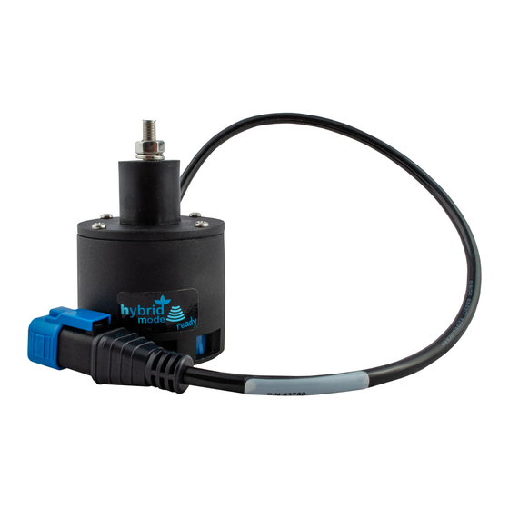
Position Sensor Installation 1. The position sensor (E06) should be mounted such that the largest amount of travel of the sensor can be utilized without exceeding the travel limit. The sensor install length is 17” (430mm) center to center with ±3.5” (±90mm) travel recommended. It should be mounted with the cable on the bottom in a location where the sensor will not bind or contact. -
Page 21: Module Installation
Module Installation An optional module mounting bracket kit is available for purchase from NORAC. mounting brackets are compatible with control modules and input modules. One kit is needed per module. Item Part Number Name Quantity 43708 UC5 MOUNTING BRACKET KIT (CONTROL AND INPUT MODULES) Control Module 1. -
Page 22: Valve Module
Valve Module 1. Install the valve module (E02) to the top of the NORAC valve block. Orient the 6-pin Deutsch (CANbus) connectors towards the “P” and “T” ports with the label facing up. Output Number Normal Function Left Up Left Down... - Page 23 Figure 17: Valve Module Bracket Installation 5. Connect the valve module CANbus to cable C01 from the control module. Route cable C02 from the other CANbus connector to the input module. 6. With the valve module securely mounted to the valve block, connect the valve cables (C10), to the valve coils.
- Page 24 Input Module 1. Install the input module (E03) on the boom near the John Deere valve block. Secure it to the boom using cable ties or optional brackets. 2. Connect the CANbus cable (C02) from the valve module to the input module. 3.
- Page 25 Figure 20: Valve Block Solenoid Locations...
-
Page 26: Connecting The Sensors To The Canbus
Connecting the Sensors to the CANbus 1. Fasten the 8-way coupler to the boom with cable ties. The recommended mounting location is shown in Figure 12. 2. Route cable C03 from the input module to the 8-way coupler (E11). 3. Connect the position sensor (E06) to the 8-way coupler using cable C02 and a 2-way coupler (E12). -
Page 27: Hydraulic Installation
Component failure due to oil contamination is not covered under the NORAC UC5 system warranty. It is recommended that a qualified technician perform the hydraulic installation. - Page 28 11. Install the setscrew (F11) into the Sense Line Bleed Orifice location. Ensure the setscrew is threaded entirely into the hole and tightened to 35-40 in-lbs (4-4.5 Nm) to ensure a tight seal. Reinstall the plug and tighten to 35-40 in-lbs (4-4.5 Nm). Figure 22: NORAC Valve Block Details...
- Page 29 Remove this coil Figure 23: Load Sense Bleed Orifice Location on Top of Block...
- Page 30 10.3 Valve Block Mounting 1. A good mounting location for the valve block on the John Deere is illustrated in Figure 24. This will require remounting the hose clamp as shown. Note: The valve block cannot be mounted on the top of the boom. If the valve block is mounted on top, it will be hit when the boom rolls.
- Page 31 10.4 Wing Roll Cylinder Mounting 1. Install the WRC mounting bracket (B07) on the boom frame as shown in Figure 25. Clamp bracket to boom frame using supplied hardware. Tighten hardware to 30-40 ft-lb (41-54 Nm). Figure 25: WRC Mounting Bracket Installed on Boom Frame 2.
- Page 32 11. Connect four (4) hoses (H02) between the 90 degree fittings (F06). 12. The “raise” lines must be connected to the "B" ports of the NORAC valve block. The “lower” lines of the cylinders must be connected to the "A" ports of the NORAC block.
- Page 33 John Deere hose, so that the orifice restricts flow of both the John Deere controls and the NORAC controls. 15. Connect hose H03 to the “S” port of the NORAC block. 16. Insert a 6FORXR-6MORT tee (F05) into the existing load sense connection. Install the 4MOR-6FORX fitting (F10) onto the F05 tee.
- Page 34 Figure 27: Fittings Installed on NORAC Valve Block Main Lift Pressure Load Sense Tank Figure 28: Pressure, Tank, Load Sense and Main Lift Locations (as viewed from the leading side of the boom center)
- Page 35 Figure 29: Pressure Line Plumbing Figure 30: Load Sense Plumbing Disc Orifice between F05 and H01 Figure 31: Main Lift Plumbing Figure 32: Fittings and Hoses Installed at Tilt Cylinder Figure 33: WRC with Fittings and Hoses Installed...
-
Page 36: Software Setup
Move the left tilt cylinder full stroke three times. b) Move the right tilt cylinder full stroke three times. 2. The NORAC screen on the VT or PULSE must be used to remove air from the roll channel: a) Start an Automatic Install. - Page 37 3. Run a complete automatic install. 11.1.2 Using an AgLeader Proprietary Display This section is only for AgLeader displays with the UC5 on the proprietary display. If the UC5 is operating on the VT within the AgLeader screen, follow the procedure in Section 11.1.1.
- Page 38 6. Run a complete automatic install (Figure 34 and Figure 35). Figure 34: Navigating to NORAC Setup Screen Figure 35: Automatic Setup...
- Page 39 Figure 36: Roll Gain Screens 11.2 JD Tilt Sensor Calibration Instructions 1. Ensure the NORAC system is plugged in and powered up. Figure 37: Calibration Screen (Tilt Sensor Selection)
- Page 40 1. Warm up the hydraulic oil to at least 60°C. The calibration screen it will show the oil temperature. 2. Ensure the NORAC system is plugged in and powered up. 3. Test the JD Autofold. Press and hold the foot switch and main up to fold. Press and hold the foot switch and main down to unfold.
- Page 41 Figure 39: Calibration Screen (Tilt Valve Selection) 5. Select the Calibration softkey (A) to view the setup menu. 6. Select the Boom Calibration tab (B). 7. Select Calibration icon (C) next to Tilt Sensor Calibration. 8. Boom Tilt Valve Calibration screen will appear.
- Page 42 12. When the calibration is complete, press the Enter button (D) to exit calibration. 13. Table 2 shows examples of “before” and “after” calibration values. The new values should be slightly higher to account for the additional UC5 wiring on the John Deere valve. Table 2: Calibration Value Examples...
-
Page 43: Cable Drawings
12 Cable Drawings 12.1 ITEM C01: 43220-10 - CABLE UC5 NETWORK 14 AWG - 10M 12.2 ITEM C02: 43220-01 - CABLE UC5 NETWORK 14 AWG - 1M... - Page 44 12.3 ITEM C03: 43220-03 - CABLE UC5 NETWORK 14 AWG - 3M 12.4 ITEM C05: 43210-20 - CABLE UC5 NETWORK 18 AWG - 20M...
- Page 45 12.5 ITEM C10: 43230-04 – CABLE UC5 VALVE DT TO DT...
- Page 46 12.6 ITEM C20: 43240-41 – CABLE UC5 INTERFACE TILT DT R4038...
- Page 47 12.7 ITEM C21: 43240-38 – CABLE UC5 INTERFACE JOHN DEERE R4030 4038 ML...
- Page 48 12.8 ITEM C30: 43250-07 – CABLE UC5 BATTERY JD FUSED...
-
Page 49: Appendix A: Optional Severe Terrain Sensor Mounting
13 Appendix A: Optional Severe Terrain Sensor Mounting When installing the severe terrain option, the inner wing sensor brackets should be mounted as shown in Figure 41. Always follow the sensor mounting guidelines to ensure optimal sensor performance and prevent sensor measurement error. Figure 41: Inner Wing Sensor Bracket Mounting... - Page 50 Canada NORAC Systems International Inc. Phone: (+1) 306 664 6711 Toll Free: 1 800 667 3921 Shipping Address: 3702 Kinnear Place Saskatoon, SK S7P 0A6 United States NORAC, Inc. Phone: (+1) 952 224 4142 Toll Free: 1 866 306 6722...
Need help?
Do you have a question about the UC5 and is the answer not in the manual?
Questions and answers