
Related Manuals for Nidek Medical ARK-500A


Summary of Contents for Nidek Medical ARK-500A
- Page 1 Заказывайте у нас на сайте www.euromed.in.ua AUTO REF/KERATOMETER ARK-500A Model OPERATOR’S MANUAL...
-
Page 2: Front View
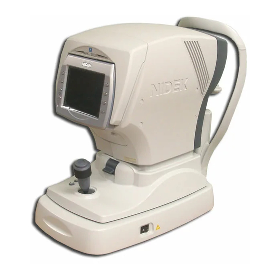
BEFORE USE: Configuration Configuration Front view Function buttons Memory indicator Start button Locking lever Joystick Power switch Cover open button Printer cover Function buttons Set the device and switch the screen. Functions assigned to the function buttons are displayed by icons on the screen. Two buttons on the left of the screen have unique functions when the measurement screen is displayed. - Page 3 BEFORE USE: Configuration Заказывайте у нас на сайте www.euromed.in.ua • Print button ( Pressing this button when the memory indicator is lit, prints out the measured data. Pressing the button when the memory indicator is not lit, advances printer paper. 5.7-inch LCD.
-
Page 4: Rear View
BEFORE USE: Configuration Rear view Forehead rest Eye level marker Measuring window Chinrest up/down buttons Chinrest PD window Forehead rest During measurement, the patient’s forehead should be gently rest against the forehead rest. Clean the chinrest for each patient. Measuring window Check the window cleanliness before measurement. -
Page 5: Bottom View
Connecting the lensmeter to the side and the RT-2100/RT-5100 to the side allows data transmission to the connected refractor via the ARK-500A. USB-A port Connect the optional barcode scanner. Do not connect equipment other than the barcode scanner. -
Page 6: Measurement Screen Layout
BEFORE USE: Measurement Screen Layout Measurement Screen Layout The screen for AR (refractive error) and KM (corneal curvature radius) measurements is comprised of pages 1 to 3. Each page differs only in the touch icons displayed to the right of the screen. <When Page 1 is displayed>... - Page 7 BEFORE USE: Measurement Screen Layout <When Page 2 is displayed> CS, PS, and PD data, ID indication, Eye Care card and cataract measurement mode indication are displayed on each page. Заказывайте у нас на сайте ID indication www.euromed.in.ua CAT measurement mode in- CYL mode button dication PS (Pupil Size) indication...
- Page 8 BEFORE USE: Labels Labels Cautionary labels are provided on the device. If labels are curling up or characters fading and becoming barely legible, contact NIDEK or your autho- rized distributor. Indicates that caution must be taken. Refer to the operator’s manual before use. Indicates a Type B applied part as a degree of protection against electric shock for applied parts.
-
Page 9: Checking Contents
BEFORE USE: Checking Contents [Bottom side] Checking Contents Unpack the contents from the shipping carton and check them. The following are included in the standard configuration. • Main body • Printer paper (3 rolls) • Power cord • Dust cover •... -
Page 10: Before First Use
BEFORE USE: Before First Use Before First Use Place the device on a stable table and connect a power cord to it. Place the main body on a stable table. Pull the main body fully to the side on which Power inlet the device is laid down, lock the main body to the base unit with the locking lever and lay the... -
Page 11: Turn On The Power Switch
BEFORE USE: Before First Use Turn ON ( ) the power switch. The initial screen is displayed on the LCD and the device starts initializing. Initial screen Confirm that the measurement screen is dis- played. Measurement screen • When the device is used for the first time, “NO PAPER” appears indicating that no paper is loaded. -
Page 12: Preparation For Measurement
OPERATING PROCEDURES: Preparation for Measurement Preparation for Measurement Turn the power switch on ( Заказывайте у нас на сайте www.euromed.in.ua Power switch The title screen is displayed and the device is ini- tialized. Wait for a while until the screen switches to the measurement screen. - Page 13 OPERATING PROCEDURES: Preparation for Measurement The measurement screen is displayed. Measurement screen • If the power is turned on with no paper loaded, the error message “NO PAPER” appears. Supply printer paper. Perform checks before use. Perform the following checks before use. No error message appears.
- Page 14 See “2.12 Parameter Settings” (page 60) for the setting procedure. 3 : Parameter-set measurement conditions: The ARK-500A is equipped with a function to change parameters of various device conditions according to the operator’s needs. See “2.12 Parameter Settings” (page 60) for details.
- Page 15 OPERATING PROCEDURES: Preparation for Measurement • Cylinder mode can be changed even after measurement. • All saved data is printed out along with the mode status. • These settings are retained even after shutdown of the device; Change these measurement conditions only if necessary. Prepare the patient.
- Page 16 ) is displayed on the screen. Limit indication • When the ARK-500A displays a thumbnail, the limit indication ( ) is covered and cannot be seen. Start measurement. For details of each measurement, see: “2.3 AR (refractive error) and KM (corneal curvature radius) Measurements: AR/KM Measurement...
-
Page 17: Switching To Manual Mode
OPERATING PROCEDURES: Preparation for Measurement 2.2.2 Switching to manual mode It is possible to turn off both the auto-tracking and auto-shooting functions (manual mode) by pressing the manual mode button during measurement. The manual mode button is used to turn off the auto-tracking function according to the patient’s eye after starting measurement with the auto-tracking function on. -
Page 18: Sleep Mode
OPERATING PROCEDURES: Preparation for Measurement 2.2.3 Sleep mode The device goes into sleep mode automatically to save power if no button have been pressed for a certain period of time. The time that the device goes into sleep mode can be selected from 5 minutes, 10 minutes, 15 minutes, or NO (no sleep mode) (factory setting: 5 minutes). - Page 19 OPERATING PROCEDURES: AR (refractive error) and KM (corneal curvature radius) Measurements: AR/KM AR (refractive error) and KM (corneal curvature radius) Measurements: AR/KM Measurement Mode In AR/KM measurement mode, AR measurement and KM measurements are successively taken. When AR/KM measurement mode is selected, refractive errors (S, C and A) and corneal curvature radius (R1, R2) are displayed on the screen.
- Page 20 OPERATING PROCEDURES: AR (refractive error) and KM (corneal curvature radius) Measurements: AR/KM Measurement Mode Manipulate the joystick to display the patient’s eye on the screen. By moving the joystick laterally, the main body moves right, left, back and forth. By turning the upper part of the joystick, the main body moves up and down.
- Page 21 OPERATING PROCEDURES: AR (refractive error) and KM (corneal curvature radius) Measurements: AR/KM Auto-tracking OFF 1) Manipulate the joystick to perform rough Up-and-down and side-to-side alignment: Manual alignment and focusing. 2) Manipulate the joystick to move the mire ring reflected on the patient’s eye within the target.
- Page 22 OPERATING PROCEDURES: AR (refractive error) and KM (corneal curvature radius) Measurements: AR/KM Measurement Mode Focusing indicator displays: The focusing indicator indicates the distance between the main body and the patient’s eye. Move the joystick back and forth until the focusing indicator shows the optimum condition.
- Page 23 OPERATING PROCEDURES: AR (refractive error) and KM (corneal curvature radius) Measurements: AR/KM KM measurement takes place. A short beep is produced and KM-measured data and measurement count are dis- played. KM measurement completes. Pre-AR measurement takes place and the scenery chart is fogged. AR measurement takes place.
- Page 24 OPERATING PROCEDURES: AR (refractive error) and KM (corneal curvature radius) Measurements: AR/KM Measurement Mode <AR measurement error messages> Error message Details Measurement is impossible due to blinking and slight movement of the eye. Instruct the patient not to blink or not to move the eye until measurement is completed.
- Page 25 OPERATING PROCEDURES: AR (refractive error) and KM (corneal curvature radius) Measurements: AR/KM Measurement completes. • When AI mode is YES: When the specified number of KM measurements is performed, the measurement automatically completes. When the specified number of AR measurements is performed and the data is stable (no varia- tions), the measurement automatically completes.
- Page 26 OPERATING PROCEDURES: AR (refractive error) and KM (corneal curvature radius) Measurements: AR/KM Measurement Mode Measure the other eye in the same manner. When the other eye is set in front of the measur- ing unit, the measuring unit returns to the origin in the back-and-forth and side-to-side directions.
-
Page 27: Cataract Measurement Mode
OPERATING PROCEDURES: AR (refractive error) and KM (corneal curvature radius) Measurements: AR/KM 2.3.1 Cataract measurement mode If cataract or abnormal eyes cannot be measured during AR (refractive error) measurement, cataract measurement mode turns on automatically. In cataract measurement mode, measurement conditions are changed so as to enhance ease of mea- surements of even cataract or abnormal eyes. -
Page 28: Measurement Ring Image Display
2.3.2 Measurement ring image display The ARK-500A projects measurement beams on the patient’s fundus and computation is performed by capturing the reflected beams as a ring image to measure the refractive errors of the patient’s eye. The ARK-500A displays this ring for the operator to observe the patient’s eye. -
Page 29: Ar (Refractive Error) Measurement: Ar Measurement Mode
OPERATING PROCEDURES: AR (refractive error) Measurement: AR Measurement Mode AR (refractive error) Measurement: AR Measurement Mode Perform AR measurement in the same manner as AR/KM measurement mode. KM (corneal curvature radius) measurement is not performed; KM-measured data is not displayed on the screen. - Page 30 OPERATING PROCEDURES: AR (refractive error) Measurement: AR Measurement Mode • If the device gets out of alignment and focus during measurement, the measurement is interrupted. If the measurement is retried, the measured results are added to the former results and saved. •...
-
Page 31: Km (Corneal Curvature Radius) Measurement: Km Measurement Mode
OPERATING PROCEDURES: KM (corneal curvature radius) Measurement: KM Measurement Mode KM (corneal curvature radius) Measurement: KM Measurement Mode Perform KM measurement in the same manner as AR/KM measurement mode. AR (refractive error) measurement is not performed; AR-measured data is not displayed on the screen. - Page 32 OPERATING PROCEDURES: KM (corneal curvature radius) Measurement: KM Measurement Mode • If the device gets out of alignment and focus during measurement, the measurement is interrupted. If the measurement is retried, the measured results are added to the former results and saved. •...
- Page 33 OPERATING PROCEDURES: View Comparison Function View Comparison Function A view comparison function allows the patient to compare the current view (uncorrected eye view or that corrected by LM data) with the view corrected by AR measurement. By changing the distance to the chart, the patient can also experience the view for near vision.
- Page 34 OPERATING PROCEDURES: View Comparison Function Press the view comparison button again to present the uncorrected eye view (or that corrected by LM data). Blinking SE of (or LM) indicates the uncorrected eye view (or that corrected by LM data) at the moment. Blinking shows which view is presented at the moment.
- Page 35 OPERATING PROCEDURES: View Comparison Function • Regardless of the view (AR measurement, uncorrected eye, LM data) presented, the view for near vision is presented by pressing the near button 2) If necessary, switch to the view with addition power. Pressing the ADD button with “<40 cm>”...
- Page 36 OPERATING PROCEDURES: View Comparison Function Заказывайте у нас на Operation on view comparison screen сайте www.euromed.in.ua Measurement screen Distance vision Distance vision Near vision Near vision Near vision with ADD power Near vision with ADD power Uncorrected eye view or that Objectively corrected view (AR corrected by LM data measurement)
-
Page 37: Cs (Corneal Size) Measurement
OPERATING PROCEDURES: CS (Corneal Size) Measurement CS (Corneal Size) Measurement Press the CS/PS/PD button to enter CS measurement mode. “<<CORNEAL SIZE>>”, guide lines and “START SW: CAPTURE” are displayed on the screen. Pressing the CS/PS/PD button switches the mode in the following order: AR/KM→... - Page 38 OPERATING PROCEDURES: CS (Corneal Size) Measurement Press the right button or left button align the guide line with the left end of the patient’s cornea. Move the guide line to the left end of the pa- tient’s cornea. Press the start button to confirm the measure- ment.
-
Page 39: Ps (Pupil Size) Measurement
OPERATING PROCEDURES: PS (Pupil Size) Measurement PS (Pupil Size) Measurement This is the procedure to measure the pupil size (PS). To measure PS continuing from CS (Corneal Size) measurement, start from Step 5. • If the mode is switched to PS measurement mode from when a still image is displayed on the CS (Corneal SIze) measurement screen, a still image is displayed. - Page 40 OPERATING PROCEDURES: PS (Pupil Size) Measurement • When the right button or left button has never been pressed, the measured values are not displayed. Start measurement again from capturing. Press the right button or left button align the guide line on the right of the patient’s pupil.
-
Page 41: Pd (Pupillary Distance) Measurement
OPERATING PROCEDURES: PD (Pupillary Distance) Measurement PD (Pupillary Distance) Measurement 2.9.1 Auto-PD measurement When the 63. AUTO PD parameter is set to YES, at the moment where measurement of both eyes is completed, PD measurement is also completed and then the PD value is displayed. - Page 42 OPERATING PROCEDURES: PD (Pupillary Distance) Measurement After proper alignment of the right eye and left eye, press the start button each time. To measure monocular PD at the same time as the binocular PD, press the start button every after proper alignment of the right-eye, center, and the left-eye.
- Page 43 OPERATING PROCEDURES: Measuring Hard Contact Lenses Place the model eye/CL holder with the sur- face of the contact lens to be measured facing toward the measuring window and insert the fixing pins. Select the KM measurement mode and measure the lens in the same manner as KM measurement.
- Page 44 OPERATING PROCEDURES: Printing <Sample printout 2> Patient No. Patient ID*1 Space for name and sex Date and time of measurement Vertex distance*2 Near working distance*3 AR measurement, Confidence index*4 S = Spherical powers C = Cylindrical powers A = Cylinder axis AR median values*5 SE value*6 Eyeprint*7...
-
Page 45: Printing Parameter Settings
OPERATING PROCEDURES: Printing 2.11.3 Printing parameter settings The parameter settings, set time, comments and maintenance program versions are printed out. Press the parameter button for about a second. The PARAMETER SETTING screen is displayed. The parameter No. and parameter names are displayed. -
Page 46: Parameter Settings
OPERATING PROCEDURES: Parameter Settings 2.12 Parameter Settings The present parameter settings, set time, comments and program versions are printed out. Press the parameter button for about a sec- ond. The PARAMETER SETTING screen is displayed and parameter items are displayed. The currently selected parameter item is high- lighted. - Page 47 OPERATING PROCEDURES: Parameter Settings Press the execute button to switch to the [PRINT1] screen. Parameters and their settings are displayed. A parameter that is being selected is highlighted. PRINT1 screen Press the up/down button to select a parameter to be changed. Move the highlight.
-
Page 48: Resetting The Parameters
OPERATING PROCEDURES: Parameter Settings To change the page of parameter: Page up button Displays the previous page. Page down button Displays the next page. Repeat Steps 4 to 5 to change the desired parameter settings. To finish setting the parameters, press the exit button The set parameter settings are saved even after power-off. -
Page 49: Parameter Tables
OPERATING PROCEDURES: Parameter Settings 2.12.1 Parameter tables [AR (AR measurement)] * Underlined options indicate factory settings. Parameter Settings STEP 0.01D / 0.12D / 0.25D VERTEX D. 0.00mm / 10.50mm / 12.00mm / 13.75mm / 15.00mm / 16.50mm AXIS STEP 1°/ 5° MEAS MODE CON. - Page 50 OPERATING PROCEDURES: Parameter Settings 6 : AR CONTINUE (successive AR measurement) Sets the measurement count for a single eye. When the AI MODE parameter is set to OFF, the measurement automatically completes after the spec- ified number of measurements. When the AI MODE parameter is set to ON, variations in data are checked after the specified number of measurements.
- Page 51 OPERATING PROCEDURES: Parameter Settings [COMPARE (View comparison function)] * Underlined options indicate factory settings. Parameter Settings COMPARE SW AUTO / MANUAL / NO COMPARE(AR) SE / -SPH ADD SW YES / NO ADD SELECT 1.50D / 1.75D / 2.00D 21 : COMPARE SW (comparison function button) Selects how to enter the view comparison function screen.
- Page 52 OPERATING PROCEDURES: Parameter Settings [PRINT1 (Print setting 1)] * Underlined options indicate factory settings. Parameter Settings PRINT MANUAL / AUTO / NO ECONO. PRINT YES / NO PRINT&CLEAR YES / NO PRINT DENSITY LOW / MIDDLE / HIGH PATIENT NO. YES / NO SET PATIENT NO.
-
Page 53: Connecting To The Nidek Motorized Refractor (Rt) Or Computer
OPERATION WHEN PERIPHERAL DEVICES ARE CONNECTED The ARK-500A exports data to an external device such as the NIDEK motorized refractor (hereafter referred to as RT) and computer. It also imports data from the NIDEK lensmeter (hereafter referred to as LM). -
Page 54: Connecting Procedure
The ARK-500A automatically transmits data to the RT (or computer). When the ARK-500A is connected to the RT, it receives data No. (ID No.) from the RT. When the ARK-500A is connected to a computer, it does not receive data No. (ID No.). -
Page 55: Connecting To The Nidek Auto Lensmeter (Lm)
Connecting to the NIDEK Auto Lensmeter (LM) 3.2.1 Outline The ARK-500A imports data measured with the NIDEK lensmeter, and prints the LM data (lensmeter readings). It also exports the LM data to the connected RT. (The lensmeter provided with this function is needed.) Connectable devices: LM-500, LM-970, LM-990/990A, LM-1000/1000P, LM-1200 The LM data transmitted to the RT is used as previous eyeglass lens values in the subjective test. - Page 56 Operating procedure After lens measurement with the LM, press the print button on the LM. The ARK-500A receives lensmeter readings from the LM. • When the device communicates with the LM, set the communication parameters of each instrument as follows. See the operator’s manual for the setting method of each device.
- Page 57 For the DIP switch settings, only set SW3 of the DIP switchpack of the Eye Care card system located at the bottom to the “ON” position. Objectively measured data EyeCa-RW Eye Care card EyeCa-RW ARK-500A AUTO OPTOMETRY SYSTEM 3.3.2 Connecting procedure Connect the interface cable of the EyeCa-RW to the data output port ( Interface cable...
- Page 58 The EyeCa-RW emits a short beep and the access indicator illuminates in green. If the ARK-500A has not measured data in its memory, the memory indicator of the ARK- 500A is shut off. Access indicator...
- Page 59 After the access indicator of the EyeCa-RW starts flashing in green, eject the Eye Care card. The data in the memory of the ARK-500A is automatically erased when the next measure- ment has begun. • Never eject the Eye Care card while it is being accessed.
- Page 60 If a patient ID is read after measured data has been printed and is still displayed, the device con- siders the displayed data to be that of a former patient and erases it automatically. • The ARK-500A considers the patient ID entered before printing to be the ID of the printed data.
- Page 61 OPERATION WHEN PERIPHERAL DEVICES ARE CONNECTED: Reading Patient IDs Place the scanner window over the barcode. Scanner window Trigger button Press the trigger button. Confirmation LED The scanner window blinks in red and the bar- code is read. After the barcode has been read successfully, the confirmation LED lights up and the scanner emits a short beep.
- Page 62 OPERATION WHEN PERIPHERAL DEVICES ARE CONNECTED: Reading Patient IDs...
-
Page 63: Maintenance
MAINTENANCE Troubleshooting In the event that the device does not work correctly, correct the problem according to the following table before contacting NIDEK or your authorized distributor. Symptom Remedy • The power cord may not be correctly connected. The LCD does not turn on. Reconnect it securely. - Page 64 MAINTENANCE: Troubleshooting Symptom Remedy • The auto-tracking function or auto-shooting function may not have been turned on. Turn them on with the auto button • Room illumination may be reflecting on the cornea. Change the location and try measurement again. •...
-
Page 65: Error Messages And Countermeasures
MAINTENANCE: Error Messages and Countermeasures Error Messages and Countermeasures If one of the following error codes is displayed on the screen or printed out, follow the suggestions in the cause and countermeasure column. The error code, detailed indications and serial number of your device are helpful in proper servicing. Error code Cause and countermeasure •... - Page 66 MAINTENANCE: Error Messages and Countermeasures Error code Cause and countermeasure • Error related to control signals for communication (input port) ERR021 Ensure that the communication cable is properly connected to the input port. • Also ensure that the communication parameters are properly set. •...
- Page 67 MAINTENANCE: Error Messages and Countermeasures Error code Cause and countermeasure • Error related to the AR motor ERR112 Malfunction of the AR motor is probable. • Shut off the device and contact NIDEK or your authorized distributor. • Error related to a connecting device A USB device connected to the USB-A connector was not properly recognized.
-
Page 68: Replacing Printer Paper
MAINTENANCE: Replacing Printer Paper Replacing Printer Paper When a red line appears on the side of printer paper, it means that paper is running short. In such a case, stop using the printer and replace printer paper with new one. •... - Page 69 MAINTENANCE: Replacing Printer Paper Insert new printer paper. Load printer paper as shown in the picture on the right. Set printer paper so that its end is exposed from the cover. • If the roll is loaded in such a way that paper becomes upside down, it is not possible to print data out.
-
Page 70: Fixing Chinrest Paper
MAINTENANCE: Fixing Chinrest Paper Fixing Chinrest Paper Disconnect the two fixing pins from the chinrest. Remove a proper number of chinrest papers from the pack. It is impossible to fix the whole pack of chinrest paper. Be sure to fix a stack with a thickness of 6 mm of less. -
Page 71: Checking The Ar/Km Measurement Accuracy
MAINTENANCE: Checking the AR/KM Measurement Accuracy Checking the AR/KM Measurement Accuracy To check the accuracy of measured data, use the provided spherical model eye for R/K measurement. The spherical model eye is incorporated with a contact lens holder. Remove the two fixing pins and remove the stack of chinrest paper from the chinrest. -
Page 72: Values Marked On The Labels Of The Spherical Model Eye
MAINTENANCE: Checking the AR/KM Measurement Accuracy Values marked on the labels of the spherical model eye Vertex distance Diopter (Unit: D) Corneal curvature radius (Unit: mm) • When the vertex distance is set to a value other than 12.00 mm (US: 13.75 mm), set the 2. VERTEX D. -
Page 73: Cleaning The Measuring Window
MAINTENANCE: Cleaning Cleaning When the cover or panel of the device becomes dirty, clean it with a soft cloth. For severe stains, soak the cloth in a neutral detergent, wiring well, and wipe. Finally dry with a soft, dry cloth. •... - Page 74 MAINTENANCE: Cleaning Check if the window is cleaned using a penlight. If not, clean it again with new cleaning paper. Apply light with a penlight and change the view angle to check the dirt clearly. Measuring window • When the 61. WINDOW CHECK parameter is set to YES or DAY, the measuring window is checked whether it is clean at device start-up.
-
Page 75: Cleaning The Printer
MAINTENANCE: Cleaning 4.6.2 Cleaning the printer After repeated usage, the paper slot of the auto cutter of the printer may become soiled with powdery paper. If the powdery paper settles, malfunction of the auto cutter may result. It must be cleaned then. Open the printer cover and remove the printer paper roll.
Need help?
Do you have a question about the ARK-500A and is the answer not in the manual?
Questions and answers