
Related Manuals for Nidek Medical AR-360A


Summary of Contents for Nidek Medical AR-360A
- Page 1 AUTO REFRACTOMETER, AUTO REF/KERATOMETER AR-360A, AR-330A, Model AR-310A, ARK-560A ARK-530A, ARK-510A SERVICE MANUAL November 2010 Pages in total: 172 XAR17ARDA001E/E...
- Page 2 NIDEK CO., LTD. : 34-14, Maehama, Hiroishi-cho, Gamagori, Aichi 443-0038, Japan (Manufacturer) Telephone: (81-533) 67-6611 Facsimile: (81-533) 67-6610 NIDEK CO., LTD : 3F Sumitomo Fudosan Hongo Bldg., 3-22-5, Hongo, (Tokyo Office) Bunkyo-Ku, Tokyo 113-0033, Japan Telephone: (81-3) 5844-2641 Facsimile: (81-3) 5844-2642 NIDEK INCORPORATED : 47651 Westinghouse Drive, Fremont, California 94539, U.
- Page 3 Table of Contents §1 INTRODUCTION ................1-1 §2 SAFETY PRECAUTIONS ..............2-1 §3 TROUBLESHOOTING ..............3-1 §4 SUBTROUBLESHOOTING .............4-1 4.1 Screen is not Turned On..................4-1 4.2 Arrow does not Disappear..................4-2 4.3 Charge Indicator does not Disappear..............4-2 4.4 Horizontal Movement of Main Unit is not Sluggish..........4-3 4.5 Main Unit cannot Move Horizontally.
- Page 4 4.25 Print is Blurred..................... 4-18 4.26 Measured Data cannot be Transferred..............4-19 4.27 Monitor Auto Off Function does not Operate............4-19 4.28 PRESSURE ERROR Appears in Test Mode............4-20 4.29 Voltage Supply Line of LED Power Supply............4-21 4.30 Voltage Supply Line of Power Supply..............
- Page 5 7.25 Front Stopper Switch ................... 7-14 7.26 P.S. Board ......................7-15 7.27 BA05 Replacement Unit for EMC ................ 7-17 7.28 Fixing Knob ......................7-19 §8 ADJUSTMENT .................8-1 8.1 Setting Time and Date ..................... 8-1 8.2 Adjusting Camera Position ..................8-1 8.3 Adjusting Video Signal Level ...................
- Page 6 9.4 Labels ........................9-4 9.5 Tools and Consumables List ..................9-5...
- Page 7 • For correct service, thorough understanding of the contents of this manual is required prior to the service. • Refer to the operator’s manual and parts list for the AR-360A, AR-330A, AR-310A, ARK- 560A, ARK-530A and ARK-510A. • Refer to the Service Manual Annex for important changes.
- Page 8 XAR17ARDA001E/E [This page is intentionally left blank.] 1 - 2...
- Page 9 XAR17ARDA001E/E § 2 SAFETY PRECAUTIONS <General precautions> • Servicing should be performed by NIDEK service persons or other qualified personnel. • Perform all servicing according to the procedures described in this manual. Failure to do so may cause unexpected accident or malfunction. •...
- Page 10 XAR17ARDA001E/E [This page is intentionally left blank.] 2 - 2...
- Page 11 XAR17ARDA001E/E § 3 TROUBLESHOOTING Plug the power cord and turn on the power switch. Does the startup screen appear? 4.1 Startup Screen does not Appear. Does an error appear? 4.2 An Error Appears. Can the function buttons be operated? 4.3 Function Buttons cannot be Operated. Can the main body move horizontally? 4.4 Horizontal Movement of Main Body is Sluggish.
- Page 12 XAR17ARDA001E/E Does LCD auto light off function operate? 4.10 LCD Auto Light Off Function does not Operate. Turn off the power switch. 3 - 2...
- Page 13 XAR17ARDA001E/E § 4 SUBTROUBLESHOOTING 4.1 Startup Screen does not Appear. Is the power supply voltage proper? 4.1.1 Check power supply voltage. Is the voltage of TP on the tracking board (30601- BA02) as below? Between TP6 and TP1: DC +3.3 V Replace the tracking board (30601-BA02) Between TP5 and TP1: DC +5 V (see 6.1.2).
- Page 14 XAR17ARDA001E/E 4.1.1 Checking power supply voltage Is the power supply voltage proper? Set a voltage stabilizer. Is the voltage between the P001 1st and 3rd pins Replace the primary supply part (30601-EA01) on the primary supply part (30601-EA01) the (see 8.1 and 8.2). same as the input voltage (see 8.1 and 8.2)? Are the voltages between the J51 4th and 1st, 5th and 2nd, and 6th and 3rd pins on the switching...
- Page 15 XAR17ARDA001E/E 4.1.2 Backlight of color LCD does not turn up. Are the voltages between the A27 and A28, and Replace the main board (30601-BA01) (see B27 and B28 pins of P103 (J3) on the main board 6.1.1). (30601-BA01) DC +12 V (see 8.1 and 8.2)? Are there any breaks in cable BA01-BA03 (30601- Replace cable BA01-BA03 (30601-EA13) (see 8.1 EA13) (see 8.1 and 8.2)?
- Page 16 XAR17ARDA001E/E 4.2 Error Message Appears. Does ERR001 (EEPROM error) appear? 4.2.1 ERR001 appears. Does ERR002 (clock error) appear? 4.2.2 ERR002 appears. Does PD ERROR appear? 4.2.3 PD ERROR appears. Does ERR011 (time-out error (OUT) in characters) 4.2.4 ERR011 appears. appear? Does ERR012 (receiving time-out (OUT)) appear? 4.2.5 ERR012 appears.
- Page 17 XAR17ARDA001E/E Does NO DAT (data empty (OUT)) appear? 4.2.12 NO DAT appears. Does ERR021 (time-out error in characters (IN)) 4.2.13 ERR021 appears. appear? Does ERR022 (receiving time-out (IN)) appear? 4.2.14 ERR022 appears. Does ERR023 (receiving error (IN)) appear? 4.2.15 ERR023 appears. Does ERR024 (received code error (IN)) appear? 4.2.16 ERR024 appears.
- Page 18 XAR17ARDA001E/E Does ERR032 (tracking right/left error) appear? 4.2.22 ERR032 appears. Does ERR033 (tracking forward/backward error) 4.2.23 ERR033 appears. appear? Does ERR034 (chinrest up/down error) appear? 4.2.24 ERR034 appears. Does NO PAPER appear? 4.2.25 NO PAPER appears. Does ERR043 (printer connection error) appear? 4.2.26 ERR043 appears.
- Page 19 XAR17ARDA001E/E Does ERR503 (Eye Care card power supply error) 4.2.32 ERR503 appears. appear? Does ERR601 (USB_A recognition error) appear? 4.2.33 ERR601 appears. Does ERR602 (USB_A class error) appear? 4.2.34 ERR602 appears. Does ERR121 (CYL1 initialization error) appear? 4.2.35 ERR121 appears. Does ERR122 (CYL2 initialization error) appear? 4.2.36 ERR122 appears.
- Page 20 XAR17ARDA001E/E 4.2.1 ERR001 appears. Does an error appear in 17. EEPROM ERROR DISP Perform adjustment and calibration accordingly for of the MENU mode (see 7.1.7)? the error. Rewrite the EEPROM data of the driver board (30601-BA03) (see 7.13). Is the problem resolved? Completion Replace the driver board (30601-BA03) (see 6.1.3).
- Page 21 XAR17ARDA001E/E 4.2.3 PD ERROR appears. Is the PD phototransmitter dirty? Clean the PD phototransmitter. Does PD LED (30601-EA55) light up? * Check it with a camera (a cell phone or other). Replace cable BA01-BA03 Are there any breaks in cable BA01-BA03 (30601-EA13) (see 8.1 and (30601-EA13) (see 8.1 and 8.2)? 8.2).
- Page 22 XAR17ARDA001E/E 4.2.4 ERR011 appears. Select a proper setting of the connected device. Is the setting of the connected device selected (Refer to the operator’s manual for the connected properly? device.) Are there any breaks in the cable base (30601- Replace the cable base (30601-EA52) (see 8.1 and EA52) (see 8.1 and 8.2)? 8.2).
- Page 23 XAR17ARDA001E/E 4.2.8 ERR015 appears. Perform the procedures described in “ERR011 appears” (see 4.2.4). 4.2.9 ERR016 appears. Perform the procedures described in “ERR011 appears” (see 4.2.4). 4.2.10 ERR017 appears. Perform the procedures described in “ERR011 appears” (see 4.2.4). 4.2.11 ERR018 appears. Perform the procedures described in “ERR011 appears”...
- Page 24 XAR17ARDA001E/E 4.2.17 ERR025 appears. Perform the procedures described in “ERR011 appears” (see 4.2.4). 4.2.18 ERR026 appears. Perform the procedures described in “ERR011 appears” (see 4.2.4). 4.2.19 ERR027 appears. Perform the procedures described in “ERR011 appears” (see 4.2.4). 4.2.20 ERR028 appears. Perform the procedures described in “ERR011 appears”...
- Page 25 XAR17ARDA001E/E 4.2.22 ERR032 appears. Are there any breaks in the R/L motor (30602-EA26) Replace the R/L motor (30602-EA26) (see 6.2.3). (see 8.1 and 8.2)? Is the voltage of P209 (J9) as below when each sensor of the R/L sensor (30602-EA20) is shaded (see 8.1 and 8.2)? R/L POSITION SENSOR: between the 2nd and 4th pins...
- Page 26 4.2.24 ERR034 appears. Perform the procedures described in “The Chinrest does not Move” (see 4.6). 4.2.25 NO PAPER appears. Replace the printing paper (refer to the operator’s manual for the AR-360A, AR-330A, AR- 310A, ARK-560A, ARK-530A, and ARK-510A). 4 - 14...
- Page 27 XAR17ARDA001E/E 4.2.26 ERR043 appears. Is the cover closed? Close the cover. Open the cover and close it again. Is the problem resolved? Completion Is the voltage between the P316 (J16) 1st and 2nd pins on the driver board (30601-BA03) DC +5 V (see Replace the driver board (30601-BA03) (see 6.1.3).
- Page 28 XAR17ARDA001E/E 4.2.27 ERR101 appears. Replace the wire (30601-M307) Are there any breaks in the wire (30601-M307)? (see 6.2.2). Are there any breaks in the sensor motor (30601- Replace the sensor motor (30601-EA35) EA35) (see 8.1 and 8.2)? (see 6.2.2). Is the voltage between the P306 (J6) 3rd and 4th pins on the driver board (30601-BA03) as below when the sensor of the sensor origin (30601-EA36) Replace the sensor origin (30601-EA36) (see 6.5).
- Page 29 XAR17ARDA001E/E 4.2.30 ERR501 appears. Replace the Eye Care card. Is the problem resolved? Replace the base board (30601-BA06) (see 6.1.4). Completion 4.2.31 ERR502 appears. Reinsert the Eye Care card for writing. Does ERR501 appear? Completion Replace the card. 4.2.32 ERR503 appears. Reinsert the Eye Care card for writing.
- Page 30 XAR17ARDA001E/E 4.2.34 ERR602 appears. Reinsert the Eye Care card and turn on the power again. Is the problem resolved? Completion Connect other SUB devices. Does ERR602 appear? Replace the SUB devices. Replace the base board (30601-BA05) (see 6.1.4). Is the problem resolved? Completion Replace the main board (30601-BA01) (see 6.1.1).
- Page 31 XAR17ARDA001E/E 4.2.35 ERR121 appears. Are there any breaks in the CL motor (30703- Replace the CL motor (30703-EA37) (see 6.26). EA37)? Are there any breaks in the CL sensor (30703- Replace the CL sensor (30703-EA38) (see 6.27). EA38)? Replace the driver board (30601-BA03) (see 6.1.3).
- Page 32 XAR17ARDA001E/E 4.3 Function Buttons cannot be Operated. Is there continuity when the switch on the left panel SW board (30601-BA07) is pressed (see 8.1 and 8.2)? Replace the left panel SW board (30601-BA07) (see SW1: between the 3rd and 4th pins 6.1.6).
- Page 33 XAR17ARDA001E/E 4.4 Horizontal Movement of Main Body is Sluggish. Clean the slide plate (32105-M102). Is the problem resolved? Completion Can the slide plate move in forward, backward, left, Replace the slide plate (32105-M102) (see 6.21). and right directions smoothly? Can the slide plate move to the right and left Replace the right/left spindle (30601-M201) or linear smoothly? bush (82001-LM092) (see 6.18 and 6.20.1).
- Page 34 XAR17ARDA001E/E 4.5 Measuring Unit does not Move Up or Dow by Turning Joystick. Are there any breaks in cable U/D (30601-EA25) Replace cable U/D (30601-EA25) (see 8.1 and 8.2). (see 8.1 and 8.2)? Is the voltage between the P205 (J5) 8th and 9th Replace the tracking board (30601-BA02).
- Page 35 XAR17ARDA001E/E 4.6 Chinrest does not Move. Are there any breaks in cable U/D switch (30601- Replace cable U/D switch (30601-EA25) (see 8.1 EA25) (see 8.1 and 8.2)? and 8.2). Is there continuity as below in P205 (J5) on the tracking board (30601-BA02) when the up/down Replace the U/D SW board (30601-BA09) switch is pressed (see 8.1 and 8.2)? (see 6.1.7).
- Page 36 XAR17ARDA001E/E 4.7 Measurement cannot be Performed Properly. Does an error appear? 4.2 An Error Appears. Is the observed image displayed on the LCD 4.7.1 Observed image is not displayed on LCD monitor? monitor. Is the mire ring displayed? 4.7.2 Mire ring is not displayed. Is the focus LED (30601-EA42) displayed? 4.7.3 Focus LED (30601-EA42) is not displayed.
- Page 37 XAR17ARDA001E/E Can the KM periphery be measured? 4.7.11 KM periphery cannot be measured. Is the CS measurement data normal? 4.7.12 CS measurement data is not normal. Is the PS measurement data normal? 4.7.13 PS measurement data is not normal. Completion 4 - 25...
- Page 38 XAR17ARDA001E/E 4.7.1 Observed image is not displayed on LCD monitor. Is the voltage of P105 (J5) on the main board (30601-BA01) as below (see 8.1 and 8.2)? Replace the main board (30601-BA01) (see 6.1.1). Between the 3rd and 2nd pins: DC +12 V Between the 4th and 5th pins: DC +5 V Are there any breaks in cable ARCCD2 (30601- Replace cable ARCCD2 (30601-EA12) (see 8.1 and...
- Page 39 XAR17ARDA001E/E 4.7.3 Focus LED is not displayed. Are there any breaks in the cable mire (30601-EA39) Replace the cable mire (30601-EA39) (see 8.1 and (see 8.1 and 8.2)? 8.2). Is the voltage between the 1st and 2nd pins of J2 and J3 DC +4 V or more when P402 and P403 on Replace the mire ASSY.
- Page 40 4.7.5 Alignment is not automatically performed by 3D auto-tracking function. 4.7.5.1 Alignment is not performed in left/right direction. * Applicable for AR-330A, ARK-530A, AR-360A, and ARK-560A only Does an error appear when the power is turned on? 4.2 An Error Appears.
- Page 41 XAR17ARDA001E/E 4.7.5.2 Alignment is not performed in up/down direction. Does an error appear when the power is turned on? 4.2 An Error Appears. Is the auto-tracking mark displayed? Display the auto-tracking mark. Is the mire ring displayed? (Check it by using a 4.7.2 Mire ring is not displayed.
- Page 42 XAR17ARDA001E/E 4.7.5.3 Alignment is not performed in forward/backward direction. * Applicable for AR-330A, ARK-530A, AR-360A, and ARK-560A only Does an error appear when the power is turned on? 4.2 An error appears. Is the auto-tracking mark 3D displayed? Display the auto-tracking mark 3D.
- Page 43 XAR17ARDA001E/E 4.7.6 Measurement does not start even when Start button is pressed. Activate the manual mode. Is there continuity between the P902 1st and 2nd pins on the joystick (30601-EA92) when the Start Replace the joystick ASSY. (30601-2100) (see 6.8). button is pressed (see 8.1 and 8.2)? Are there any breaks in cable U/D (30601-EA25) Replace cable U/D (30601-EA25) (see 8.1 and 8.2).
- Page 44 XAR17ARDA001E/E 4.7.8 AR measurement data is not normal. Does BLK (blink error) appear when a model eye 4.7.8.1 BLK (blink error) appears. is measured? Is the result thumbnail displayed properly on the Perform the AR calibration (see 7.6). LCD monitor after the AR measurement? Are there any breaks in cable ARCCD1 (30601- Replace cable ARCCD1 (30601-EA72) (see 8.1 EA72) (see 8.1 and 8.2)?
- Page 45 XAR17ARDA001E/E 4.7.8.1 BLK (blink error) appears. Is the result thumbnail displayed properly on the Perform the AR calibration (see 7.6). LCD monitor after the AR measurement? Are there any breaks in cable ARCCD1 (30601- Replace cable ARCCD1 (30601-EA72) (see 8.1 EA72) (see 8.1 and 8.2)? and 8.2).
- Page 46 XAR17ARDA001E/E 4.7.10 KM measurement data is not normal. Are there any breaks in the mire cable (30601-EA39) Do the mire ring and focus LED light up? (see 8.1 and 8.2)? Replace the mire ASSY. (30601-4000) Replace the mire cable (30601-EA39) (see 6.1.1).
- Page 47 XAR17ARDA001E/E 4.7.12 CS measurement data is not normal. Perform the CS PS calibration (see 7.12). 4.7.13 PS measurement data is not normal. Perform the CS PS calibration (see 7.12). 4.8 Communication cannot be Performed Properly. Perform the procedures described in “ERR011 appears” (see 4.2.4). 4.9 Printout cannot be Performed.
- Page 48 XAR17ARDA001E/E 4.10 LCD Auto Light Off Function does not Operate. Is the sleep mode activated? Activate the sleep mode. (Refer to the operator’s manual.) (Refer to the operator’s manual.) Are there any breaks in the flexible flat cable (30601- Replace the flexible flat cable (30601-E021) (see 8.1 E021) (see 8.1 and 8.2)? and 8.2).
- Page 49 XAR17ARDA001E/E § 5 REMOVING PROCEDURES 5.1 Left Cover of Measuring Unit 1. Remove the caps [32105-M730 (n = 4)]. 2. Unscrew PC3 × 8 (n = 4). 3. Remove the left cover (30601-M707) of the measuring unit. 4. Reassemble the parts in reverse order. 5.2 Right Cover of Measuring Unit 1.
- Page 50 XAR17ARDA001E/E 5.3 Front Cover ASSY. of Measuring Unit 1. Remove the caps [32909-M541 (n = 4)]. 2. Unscrew PC3 × 8 (n = 4). 3. Remove the front cover ASSY. (30601-6300) of the measuring unit. 4. Reassemble the parts in reverse order. 5.4 Front Body Cover 1.
- Page 51 XAR17ARDA001E/E 5.6 Rear Body Cover ASSY. 1. Move the measuring unit to the top position. 2. Remove the front cover ASSY. of the measuring unit, front cover of the body, and rear cover ASSY. of the measuring unit (see 5.3, 5.4 and 5.5). 3.
- Page 52 XAR17ARDA001E/E 5.8 Dust Cover 1. Remove the right and left covers of the measuring unit, and the rear and front cover ASSYs of the measuring unit (see 5.1, 5.2, 5.3, and 5.5). 2. Unscrew AS3 × 6 (n = 2) on top of the dust cover (30601-M304) and loosen AS3 ×...
- Page 53 XAR17ARDA001E/E 5.10 LCD Front Cover 1. Remove the LCD ASSY. (30601-6100) (see 6.14). 2. Unscrew PC3 × 5 (n = 4) to remove the LCD rear cover (30601-M716). 3. Disconnect connector P701 (J1) on the left panel SW board (30601-BA07) and connector P71501 (J1) on the right panel SW board (30601-BA15).
- Page 54 XAR17ARDA001E/E [This page is intentionally left blank.] 5 - 6...
- Page 55 10. Reassemble the parts in reverse order. 11. After the replacement, turning on the power displays the errors below. 1) The AR-310A, AR-330A, AR-360A: ERR065 2) The ARK-510A, ARK-530A, ARK-560A: ERR066 * Do not turn the power off until the errors are displayed.
- Page 56 5. Reassemble the parts in reverse order. 6. After the replacement, turning on the power displays the errors below. 1) The AR-310A, AR-330A, AR-360A: ERR065 2) The ARK-510A, ARK-530A, ARK-560A: ERR066 * Do not turn off the power until the errors are displayed.
- Page 57 XAR17ARDA001E/E 6.1.4 Base board Replacement part: 30601-BA05 1. Remove the base plate (30601-M002) (see 5.7). 2. Disconnect all connectors on the base board (30601-BA05). 3. Unscrew BS3 × 8 (n = 3) and TW3 (n = 2), and disconnect the connector cable (30601-EA01) and the earth cable on the base board (30601- BA05).
- Page 58 XAR17ARDA001E/E 6.1.5 LCD board Replacement part: 30601-BA06 1. Open the LCD ASSY. (30601-6100) and remove the rear LCD cover (30601-M716) (see 5.9). 2. Disconnect all connectors on the LCD board (30601-BA06). 3. Unscrew PC2 × 4 (n = 2). 4. Replace the LCD board (30601-BA06). 5.
- Page 59 XAR17ARDA001E/E 6.1.7 U/D SW board Replacement part: 30601-BA09 1. Remove the rear body cover ASSY. (30601- 7000) (see 5.6). 2. Unscrew PT3 × 5 (n = 2). 3. Replace the U/D SW board (30601-BA09). 4. Reassemble the parts in reverse order. 6.1.8 Sensor carry board Replacement part: 30601-BA14 1.
- Page 60 XAR17ARDA001E/E 6.1.9 Right panel SW board Replacement part: 30601-BA15 1. Remove the front LCD cover (30601-M715) (see 5.10). 2. Unscrew PT2 × 5 (n = 2) and replace the right panel SW board (30601-BA15). 3. Reassemble the parts in reverse order. 6.1.10 BA08 PD CCD board Replacement part: 32105-BA08 1.
- Page 61 XAR17ARDA001E/E 6.1.11 DC-AC inverter Replacement part: 18535-E010 1.Open the LCD ASSY. (30601-6100) to remove the rear LCD cover (30601-M716) (see 5.9). 2. Disconnect all connectors on the DC-AC inverter (18535-E010). 3. Unscrew PC2 × 4 (n = 2) to replace the DC-AC inverter (18535-E010).
- Page 62 XAR17ARDA001E/E 6.2.2 Sensor motor Replacement part: 30601-E035 1. Remove the dust cover (30601-M304) (see 5.8). 2. Unscrew BS3 × 6 (n = 2) to remove the pulley 2 ASSY. (30601-3120). 3. Remove the wire (30601-M307) from the pulley (30601-M359) of the motor ASSY. (30601- 3600).
- Page 63 XAR17ARDA001E/E 6.2.3 R/L motor Replacement part: 30602-EA26 * Applicable for the AR-330A, AR-360A, ARK-530A, and ARK-560A 1. Remove the covers (see Chapter 5). 2. Disconnect connector P102 (J2) on the main board (30601-BA01), connectors P201 (J1), P205 (J5), P208 (J8), P211 (J11) and the earth cable on the tracking board (30601-BA02).
- Page 64 XAR17ARDA001E/E 6.2.4 F/B motor Replacement part: 30602-EA27 * Applicable for the AR-330A, AR-360A, ARK-530A, and ARK-560A only 1. Remove the covers (see Chapter 5). 2. Remove the measuring unit together with the tracking horizontal ASSY. (30601-2500) (see 6.2.3). 3. Unscrew BS4 × 6 (n = 2) to remove the R/L motor (30602-EA27) together with the attachment plate (30602-M261).
- Page 65 XAR17ARDA001E/E 6.3 Sensors 6.3.1 R/L sensor Replacement part: 30602-EA20 * Applicable for the AR-330A, AR-360A, ARK-530A, and ARK-560A 1. Remove the covers (see Chapter 5). 2. Unscrew BS3 × 6 to replace the R/L sensor (30602-EA20). 3. Reassemble the parts in reverse order.
- Page 66 XAR17ARDA001E/E 6.4 B/W CCD Camera 6.4.1 Measurement CCD camera Replacement part: 30601-E001 1. Remove the covers (see Chapter 5). 2. Unscrew CK2 × 3 (n = 4) to remove the code retainer (30601-M346). 3. Disconnect the connector on the B/W CCD camera (30601-E001).
- Page 67 XAR17ARDA001E/E 6.5 Origin Sensor Replacement part: 30601-EA36 1. Remove the covers (see Chapter 5). 2. Unscrew CK 2 × 4 (n = 2) to replace the origin sensor (30601-EA36). 3. Reassemble the parts in reverse order. 4. Perform the chart calibration (see 7.6.5). 5.
- Page 68 XAR17ARDA001E/E 5. Unscrew PC3 × 6. 6. Unscrew HH3 × 5 (n = 3) and move the bearing (32105-M048) upward. 7. Unscrew HH3 × 5 and CK 2 × 5 (n = 2) to remove the motor brace (32105-M080). 8. Unscrew SB3 × 6 (n = 2) and PC2 × 5 (n = 2). 9.
- Page 69 XAR17ARDA001E/E 6.8 Joystick ASSY. Replacement part: 30601-2100 1. Remove the covers (see Chapter 5). 2. Disconnect the GND cable of the joystick. 3. Unscrew BS3 × 6 (n = 4) to replace the joystick ASSY. (30601-2100). 4. Reassemble the parts in reverse order. 6.9 Switching Regulator Replacement part: 80602-00102 1.
- Page 70 XAR17ARDA001E/E 6.10 Printer Replacement part: 80606-00018 1. Remove the rear cover (30601-6000) of the measuring unit (see 5.5). 2. Unscrew PT3 × 8 (n = 2) to remove the printer fixing cover (30601-M711). 3. Remove the printer door cover (30601-M710). 4.
- Page 71 XAR17ARDA001E/E 6.11 Printer Interface Board Replacement part: 80606-00019 1. Remove the rear cover ASSY. (30601-6000) of the measurement unit (see 5.5). 2. Unscrew PT3 × 8 (n = 2) to remove the printer interface board (80606-00019) together with the attachment plate and PR board (30601-M609). 3.
- Page 72 XAR17ARDA001E/E 6.13 Mire ASSY. Replacement part: 30601-4000 1. Remove the covers (see Chapter 5). 2. Disconnect connector P401 (J1) on the mire board (30601-BA04). 3. Unscrew BS3 × 8 (n = 4). 4. Replace the mire ASSY. (30601-4000). 5. Reassemble the parts in reverse order. 6.
- Page 73 XAR17ARDA001E/E 6.16 Focus LED Replacement part: 30601-EA42 1. Remove the mire ASSY. (30601-4000). (see 6.13). 2. Unscrew CK2 × 3 (n = 4). 3. Replace the focus LED [30601-EA42 (n = 2)]. 4. Reassemble the parts in reverse order. 5. Perform the alignment calibration (see 7.5). 6.
- Page 74 XAR17ARDA001E/E 6.18 Left/Right Spindle Replacement part: 30601-M201 1. Remove the covers (see Chapter 5). 2. Disconnect connector P201 (J1) on the tracking board (30601-BA02) and the GND cable of the base cable (30601-EA52). 3. Unscrew SB6 × 12 (n = 2) to remove the chinrest ASSY.
- Page 75 XAR17ARDA001E/E 6.19 Front/Back Spindle Replacement part: 30601-M103 1. Remove the left/right spindle (30601-M201) (see 6.18). 2. Unscrew HH5 × 6 (n = 4) to replace the front/ back spindles [30601-M103 (n = 2)]. 3. Reassemble the parts in reverse order. * Reassemble so that the backward/forward and left/right movements are smooth.
- Page 76 XAR17ARDA001E/E 6.20.2 Linear bush for front/back spindle Replacement part: 82001-LM028 1. Unscrew HH5 × 6 (n = 4) to remove the front/back spindles [30601-M103 (n = 2)] and front/ back slider (30601-M102) (see 6.19). 2. Unscrew TC3 × 5 (n = 4) to replace the linear bushes [82001-LM028 (n = 4)].
- Page 77 XAR17ARDA001E/E 6.22 Phototransmitter ASSY. Replacement part: 30601-3310 1. Remove the covers (see Chapter 5). 2. Disconnect connector P1405 (J5) on the sensor carry board (30601-BA14). 3. U n s c r e w H H 3 × 4 t o r e p l a c e t h e phototransmitter ASSY.
- Page 78 XAR17ARDA001E/E 6.24 Subjective Cylinder ASSY. Replacement part: 30703-3700 1. Remove the covers (see Section 5). 2. Disconnect P307 (J7) and P308 (J8) from the driver board (30601-BA03). 3.Unscrew BS3 × 8 (n = 2) to remove the subjective cylinder ASSY. (30703-3700). 4.
- Page 79 XAR17ARDA001E/E 6.27 CL Sensor Replacement part: 30703-EA38 1. Remove the subjective cylinder ASSY. (30703- 3700) (see 6.25). 2. Unscrew CK2 × 3 (n = 3) to remove the sensor retainer (30703-M395). Then remove the infrared LED from the CL sensor (30703- EA38).
- Page 80 XAR17ARDA001E/E 6.28 Chart Replacement part: 30703-EA74 1. Remove the chart disk ASSY. (30703-3800) (see 6.26). 2. Unscrew CK2 × 4 (n = 2) to remove the disk cover (30703-M404). 3. Unscrew FK2 × 3 (n = 2) to remove the holder (30703-M408) and sensor stopper (30703- M405).
- Page 81 XAR17ARDA001E/E § 7 ADJUSTMENT 7.1 Entering Adjustment Mode 7.1.1 MENU mode 1. Turn on the power switch while pressing the L- 1 and R-1 buttons of the function buttons. * Keep pressing the function buttons until a beep sounds. 2. The device starts and the password entry screen appears.
- Page 82 XAR17ARDA001E/E 7.1.2 CALIB MODE SELECT ( for AR) 1. Turn on the power switch while pressing the L- 1 and R-2 buttons of the function buttons. * Continue pressing the function buttons until a beep sounds. 2. The CALIB MODE SELECT screen appears. 3.
- Page 83 XAR17ARDA001E/E 7.1.5 Parameter settings 1. Display the PARAMETER SETTING screen following the steps below. 1) For the AR-360A, AR-330A, and AR-310A, press the ring image enlargement/ for one second or parameter button m o r e t o d i s p l a y t h e PA R A M E T E R SETTING screen.
- Page 84 XAR17ARDA001E/E 7.1.6 CALIB MODE SELECT (for KM) * The CALIB MODE SELECT screen for the KM can be displayed in the ARK-560A, ARK- 530A, and ARK-510A only. 1. Turn on the power switch while pressing the L-1 and R-3 buttons of the function buttons. * Continue pressing the function buttons until a beep sounds.
- Page 85 XAR17ARDA001E/E 7.2 Adjusting CCD Camera 7.2.1 Attaching optical adjustment jigs for servicing Jigs to be used: Relay board (30670-BA01) : Flexible flat cable (30670-E001) : Relay cable 3 (30670-EA06) : EA39 extension cable (32557-EA11) : Joint jig (30670-1100) : Reticle illumination jig (30670-1200) 1.
- Page 86 XAR17ARDA001E/E 7. Connect the connector of relay cable 3 (30670-EA06) to the connector of the reticle illumination jig (30670-1200). 8. Connect the connector of relay cable 3 (30670-EA06) to connector J3 of the mire ASSY. (30601-4000). 9. Connect the connector of the EA39 extension cable (32557-EA11) to connector J1 of the mire ASSY.
- Page 87 XAR17ARDA001E/E 11. Attach the joint jig (30670-1100) to the measuring ASSY (for replacement) (30601- 9E00) with PC3 × 15 (n = 2). 12. Attach the jigs as follows: 1) Reticle illumination jig a. Align the key (31401-M357) of the reticle illumination jig (30670-1200) with the notch of the joint jig (30670-1100) and fix it with the stepped knurled screw (82053-...
- Page 88 XAR17ARDA001E/E 7.2.2 Adjusting observation CCD camera 1. Remove the dust cover (30601-M304) (see 5.8). 2. Remove the mire ASSY. (30601-4000) (see 6.13). 3. Remove the motor ASSY. (30601-3600) (see 6.2.2). 4. Adjust the focus of the observation CCD camera as follows: 1) Attach the reticle illumination jig (30670- 1200) to the joint jig (30670-1100) (see 7.2.1).
- Page 89 XAR17ARDA001E/E 5. Adjust the position of the observation CCD camera as follows: 1) Attach 0 D model eye 2 (32177-0618) to the joint jig (30670-1100) (see 7.2.1). 2) Press the next button to display the 1- 2 CCD POSITION (OVSER.) screen. 3) Press the function buttons to display RUN and LED.
- Page 90 XAR17ARDA001E/E 6. Adjust the inclination of the observation CCD camera as follows: 1) Attach the reticle illumination jig (30670-1200) (see 7.2.1). 2) Press the next button to display the 1-3 HORIZONAL DIRECTION screen. * Press the function buttons to display RUN and LED, and adjust the brightness of the reticle illumination jig with the up or down button so that the adjustment can be...
- Page 91 XAR17ARDA001E/E 7.2.3 Measurement CCD camera 1. Remove the dust cover (30601-M304) (see 5.8). 2. Remove the mire ASSY. (30601-4000) (see 6.13). 3. Attach 0 D model eye 2 (32177-0618) (see 7.2.1). 4. Enter the MENU mode and select 5. AR CAMERA (see 7.1.1).
- Page 92 XAR17ARDA001E/E 7.3 Phototransmitter 1. When using a dark room, remove the internal reflection (see 7.3.1). 2. When not using a dark room, perform the optical axis adjustment of AR SLD (see 7.3.2). 7.3.1 Removing internal reflection * Be sure to perform the removal of internal reflection in a dark room. * Do not place any reflective object on the patient’s side.
- Page 93 XAR17ARDA001E/E 7.3.2 Optical adjustment of AR SLD 1. Remove the dust cover (30601-M304) (see 5.8). 2. Remove the mire ASSY. (30601-4000) (see 6.13). 3. Attach the 0 D model eye 2 (32177-0618) (see 7.2.1). 4. Enter the MENU mode and select 5. AR CAMERA (see 7.1.1). 5.
- Page 94 XAR17ARDA001E/E 7.4 Chart Adjustment 7.4.1 AR-310A, AR-330A, ARK-510A, ARK-530A * This adjustment should be perfromed for AR- 310A, AR-330A, ARK-510A, and ARK-530A only. * When adjustment jigs are not available, return the device to the factory without performing adjustment. 1. Remove the dust cover (30601-M304) (see 5.8). 2.
- Page 95 XAR17ARDA001E/E 7.4.2 AR-360A, ARK-560A * This adjustment should be performed for the AR-360A and ARK-560A only. * When adjustment jigs are not available, return the device to the factory without performing adjustment. 1. Remove the dust cover (30601-M304) (see 5.8).
- Page 96 XAR17ARDA001E/E b. Loosen HH3 × 4 to turn the chart lens 2 ASSY. (30601-3260). 10. After adjustment is completed, press the exit button to turn off the power. 11. Reassemble the removed covers. 12. Perform the chart calibration (see 7.6.5). 7 - 16...
- Page 97 XAR17ARDA001E/E 7.5 Alignment Calibration 1. Attach the following jigs. 1) 22-model eye jig, Chinrest attachment jig a. Attach the chinrest attachment jig (32107- 1100) to the chinrest ASSY. (30601-5000). * Fix the jig with the knobs (32177-M502, 32177-M508). b. Attach the 22-model eye jig (32171-0600) to the chinrest attachment jig (32107- 1100).
- Page 98 XAR17ARDA001E/E 2. Enter the MENU mode and select 8. ALIGNMENT CALIBRATION (see 7.1.1). 3. Align the 0 D model eye as follows: 1) Align the inner mire illuminating weakly with the target center. 2) Align and focus the outer mire. 4.
- Page 99 XAR17ARDA001E/E 7.6 AR Calibration 7.6.1 AR calibration 1.Attach the following jigs. a. Chinrest attachment jig (32107-1100) b. 22-model eye jig (32171-0600) 2. Display the CALIB MODE SELECT (for AR) screen and select AR (see 7.1.2). 3. Select CUSTOM with the up or down button, and press the set button 4.
- Page 100 XAR17ARDA001E/E 7. Enter the measurement mode (see 7.1.4). 1) For the AR-360A, AR-330A, and AR-310A, the screen shown to the right appears. 2) For the ARK-560A, ARK-530A, and ARK- 510A, the screen shown to the right appears. 8. Press the auto button...
- Page 101 XAR17ARDA001E/E 7.6.2 AR axis 1. Attach the following jigs. 1) Attach the chinrest attachment jig (32107-1100) (see 7.5). 2) Attach the cylinder axis adjustment jig (32177-1500) to the chinrest attachment jig (32107-1100) * Fix the jig with the knob (32177-M513). 2.
- Page 102 XAR17ARDA001E/E 7.6.3 AXIS OFFSET 1. Attach the chinrest attachment jig (32107-1100) and cylinder axis adjustment jig (32177-1500) (see 7.6.2). 2. Display the CALIB MODE SELECT (for AR) screen (see 7.1.2). 3. Select AR CORRECT with the up or down button and press the set button 4.
- Page 103 XAR17ARDA001E/E 7.6.5 Chart calibration (*Adjustable only in factory) 7.6.5.1 Attaching jigs 7.6.5.1.1 Chart inspection jig (32145-2100) 1. Attach the jigs as follows: 1) Attach the chinrest attachment jig (32107- 1100) (see 7.5). 2) Attach the chart inspection jig (32145- 2100) to the chinrest attachment jig (32107- 1100).
- Page 104 XAR17ARDA001E/E 7.6.5.1.2 Chart inspection jig (30670-2300) 1. Attach the jigs as follows: 1) Attach the chinrest attachment jig (32107- 1100) (see 7.5). 2) Attach the chart inspection jig (30670- 2300) to the chinrest attachment jig (32107- 1100). * Fix the jig with the knob (32177-M513). 3) Display the CALIB MODE SELECT (for AR) screen (see 7.1.2).
- Page 105 2) Disconnect connector P104 (J4) from the main board. a. AR-310A : 30601-BA01P b. AR-330A : 30602-BA01P c. AR-360A : 30603-BA01P a. ARK-510A : 30701-BA01P b. ARK-530A : 30702-BA01P c. ARK-560A : 30703-BA01P 3) Attach the chinrest attachment jig (32107- 1100) (see 7.5).
- Page 106 XAR17ARDA001E/E 7.6.5.2 AR-310A, AR-330A, ARK-510A, ARK-530A 7.6.5.2.1 Chart calibration when using chart inspection jig * If the adjustment jig is not available, return the device to the factory without performing adjustment. 1. Attach the chart inspection jig (32145-2100 or 30670-2300) (see 7.6.5.1.1 or 7.6.5.1.2). 2.
- Page 107 XAR17ARDA001E/E 7.6.5.2.2 Chart calibration when using dioptric tester jig ASSY. * If the adjustment jig is not available, return the device to the factory without performing adjustment. 1. Attach the dioptric tester jig ASSY. (30670-6000) (see 7.6.5.1.3). 2. Perform the chart calibration as follows: 1) Select CHART CALIBRATION with the up or down button, then press the set button...
- Page 108 XAR17ARDA001E/E 4. Perform CHART CHECK as follows: 1) Check the 0 D position according to the steps below. a.Turn the turret plate to select a position without any lens. b. Press the left- button or right+ but- several times. c. Perform adjustment with the left- but- or right+ button so that the whole chart is focused.
- Page 109 XAR17ARDA001E/E 7.6.5.3 AR-360A, ARK-560A 7.6.5.3.1 Chart calibration when using chart inspection jig * If the adjustment jig is not available, return the device to the factory without performing adjustment. 1. Attach the chart inspection jig (30670-2300) (see 7.6.5.1.2). 2. Perfrom the STAR CALIBRATION as follows: 1) Adjust the 0 D position according to the steps below.
- Page 110 XAR17ARDA001E/E 4. Perform THETA1 CALIB as follows: 1) Turn the turret plate to select a position without any lens. 2) Perform adjustment with the left- button or right+ button so that the clock dial chart can be seen in uniform clarity. Uniform 3) Press the SAVE button to save the position.
- Page 111 XAR17ARDA001E/E 9. Perform THETA1 CHECK as follows: 1) Turn the turret plate to select a position without any lens. 2) Press the left- button or right+ button several times. 3) Perform adjustment with the left- button or right+ button so that the clock dial chart can be seen in uniform clarity.
- Page 112 XAR17ARDA001E/E 17. Perform STAR CHECK as follows: 1) Select STAR CHECK with the up or down button, then press the set button 2) Check the 0 D position according to the steps below. a. Turn the turret plate to select a position without any lens. b.
- Page 113 XAR17ARDA001E/E 19. Perform BALOON CALIB as follows: 1) Adjust the 0 D position according to the steps below. a. Turn the turret plate to select a position without any lens. b. Press the right+ button until the whole chart is focused for the first time. c.
- Page 114 XAR17ARDA001E/E 21. Perform BALOON CHECK as follows: 1) Check the 0 D position according to the steps below. a. Turn the turret plate to select a posi- tion without any lens. b. Press the left- button or right+ but- several times. c.
- Page 115 XAR17ARDA001E/E 7.6.5.3.2 Chart calibration when using dioptric tester jig ASSY. * If the adjustment jig is not available, return the device without performing adjustment. 1. Attach the dioptric tester jig ASSY. (30670-6000) (see 7.6.5.1.3). 2. Perform STAR CALIBRATION as follows. 1) Select STAR CALIB with the up or down button, then press the set button...
- Page 116 XAR17ARDA001E/E 4. Perform THETA1 CALIB as follows: 1) Turn the turret plate to select the position without any lens. 2) Perform adjustment with the left- button and right+ button so that the whole clock dial chart is focused. 3) Press the SAVE button to save the position. Uniform * Pressing the SAVE button displays the next button...
- Page 117 XAR17ARDA001E/E 9. Perform THETA1 CHECK as follows: 1) Turn the turret plate to select the position without any lens. 2) Press the left- button or right+ button several times. 3) Perform adjustment with the left- button or right+ button so that the whole clock dial chart can be seen in uniform clarity.
- Page 118 XAR17ARDA001E/E 17. Perform STAR CHECK as follows: 1) Select STAR CHECK with the up or down button, then press the set button 2) Check the 0 D position according to the steps below. a. Turn the turret plate to select a position without any lens. b.
- Page 119 XAR17ARDA001E/E 19. Perform BALOON CALIB as follows: 1) Adjust the 0 D position according to the steps below. a. Turn the turret plate to select a posi- tion without any lens. b. Press the left- button or right+ but- several times. c.
- Page 120 XAR17ARDA001E/E 21. Perform BALOON CHECK as follows: 1) Check the 0 D position according to the steps below. a. Turn the turret plate to select a position without any lens. b. Press the left- button or right+ but- several times. c.
- Page 121 XAR17ARDA001E/E 7.6.6 Chart check * If the adjustment jig is not available, return the device to the factory without performing adjustment. 1. Attach the chinrest attachment jig (32107-1100) and chart inspection jig (32145-2100 or 30670- 2300) (see 7.6.5). 2. Display the CALIB MODE SELECT (for AR) screen (see 7.1.2). 3.
- Page 122 XAR17ARDA001E/E 3) Press the down button and adjust the -12.00 D position. a. Turn the turret plate to select the -12.00 D (33510-G018) lens. b. Press the left- button or right+ but- several times. c. Perform adjustment with the left- but- or right+ button so that the whole chart is focused.
- Page 123 XAR17ARDA001E/E 7.7 KM Calibration * Perform the KM calibration for the ARK-560A , ARK-530A, and ARK-510A only. 7.7.1 KM CALIB 1. Attach the following jigs. 1) Attach the chinrest attachment jig (32107- 1100) (see 7.5). 2) Attach the KM calibration jig (30670-0300) to the chinrest attachment jig (32107-1100).
- Page 124 XAR17ARDA001E/E 7.7.2 KM CALIB CHECK 1. Attach the chinrest attachment jig (32107-1100) and KM calibration jig (30670-0300) (see 7.7.1). 2. Display the CALIB MODE SELECT (for KM) screen (see 7.1.6). 3. Select KM CALIB CHECK with the up or down button and press the set button 4.
- Page 125 XAR17ARDA001E/E 7.7.3 KM ADJUST 1. When the KM measurement values are out of the specifications, perform ADJUST GAIN (see 7.7.3.1). 2. When the peripheral KM measurement values are out of the specifications, perform ADJUST PHI6 GAIN (see 7.7.3.2). 7.7.3.1 ADJUST GAIN 1.
- Page 126 XAR17ARDA001E/E 7.7.3.2 ADJUST PHI6 GAIN 1. Attach the chinrest attachment jig (32107-1100) and KM calibration jig (30670-0300) (see 7.7.1). 2. Display the CALIB MODE SELECT (for KM) screen (see 7.1.6). 3. Select KM ADJUST with the up or down button and press the set button 4.
- Page 127 XAR17ARDA001E/E 7.7.4 KM AXIS CHECK 1. Attach the following jigs. 1) Attach the chinrest attachment jig (32107-1100) (see 7.5). 2) Attach the aspheric model eye jig (32177- 1400). * Fix it with the knob (32177-M513). 2. Display the CALIB MODE SELECT (for KM) screen (see 7.1.6). 3.
- Page 128 XAR17ARDA001E/E 7.7.5 KM AXIS OFFSET 1. Attach the chinrest attachment jig (32107-1100) and aspheric model eye jig (32177-1400) (see 7.7.4). 2. Display the CALIB MODE SELECT (for KM) screen (see 7.1.6). 3. Select KM AXIS OFFSET with the up or down button and press the set button 4.
- Page 129 XAR17ARDA001E/E 7.7.5.2 OFFSET PHI6 AXIS 1. Perform KM AXIS OFFSET (see 7.7.5). 2. Select OFFSET PHI6 AXIS with the up or down button and press the set button 3. Perform corrections as follows: 1) Change the numeric value with the right or left button.
- Page 130 XAR17ARDA001E/E 7.8 PD Calibration 7.8.1 CENTER POSITION 1. Attach the PD checking jig (32545-1002) to the chinrest. * A scale can be used as substitute for the PD checking jig (32545-1002). 2. Enter the MENU mode and select 15. PD ADJUST MODE (see 7.1.1).
- Page 131 XAR17ARDA001E/E 7.8.2 PD CALIBRATION 1. Attach the PD checking jig (32545-1002) to the chinrest (see 7.8.1). * A scale can be used as substitute for the PD checking jig (32545-1002). 2. Enter the MENU mode and select 15. PD ADJUST MODE (see 7.1.1). 3.
- Page 132 XAR17ARDA001E/E 10.”CALIB COMPLETE” is displayed. Press the SAVE button to save the setting. 11. Press the right button and then the exit button 12.Select GAIN & OFFSET with the up or down button and press the set button 13. Measure the PD values at the 64 mm and 80 mm positions, and confirm the results meet the following specifications.
- Page 133 XAR17ARDA001E/E 7.9 CS /PS Calibration * The CS/PS calibration can be performed in the ARK-560A, ARK-530A, and ARK-510A only. 1. Attach the PD checking jig (32545-1002) to the chinrest (see 7.8.1). * A scale can be used as substitute for the PD checking jig (32545-1002). 2.
- Page 134 XAR17ARDA001E/E 7.10 AUTO TRC ADJUST * Perform adjustment only when the R/L motor (30602-EA26), F/B motor(30602-EA27), or U/D motor (30601-EA28) is replaced. In other cases, adjustment is not necessary as the factory setting is optimized. 1. Attach the simple calibration model eye (32107-6200). 2.
- Page 135 XAR17ARDA001E/E 7.11 Upgrading Software 1. Turn off the power. 2. Connect the USB flash drive (30601-E030) to the USB A connector of the main body. *USB flash drive: If 30601-E030 is not available, a USB flash drive made by SanDisk is recommended. * It is possible that the device does not recognize a USB flash drive even though it is made by SanDisk.
- Page 136 XAR17ARDA001E/E 10. After upgrading is completed, the screen shown to the right appears. Turn off the power. 11. Disconnect the USB flash drive from the device. 12. Turn on the power and confirm that the device starts properly. 13. When upgrading was not successful, start from Step 1 again .
- Page 137 XAR17ARDA001E/E 7.13 Rewriting EEPROM Data * Rewrite the EEPROM data only when the driver board (30601-BA03) is replaced. * Improper operation may delete the adjustment data saved in the driver board (30601-BA03). 1. Enter the MENU mode and select 17. EEPROM ERROR DISP (see 7.1.1).
- Page 138 XAR17ARDA001E/E 7.14 CURSOR BOARD 1. Display the CALIB MODE SELECT (for AR) screen and select CURSOR (see 7.1.2). 2. Confirm that pink lines are displayed on all four edges of the color LCD (30601-E005). 3. When the pink lines cannot be seen, adjust the position of the LCD front cover (30601- M715) (see 5.10).
- Page 139 XAR17ARDA001E/E 7.15 Subjective Cylinder ASSY. * The subjective cylinder ASSY. must be adjusted for the eyes in a state of emmetropia. For those other than emmetrope, correction is required. 1. Enter the MENU mode to select 2. CHART POSITION (see 7.1.1). 2.
- Page 140 XAR17ARDA001E/E 6. Move the subjective focus base ASSY. Measuring window (30703-3300) forward and backward so that the chart can be seen through the measuring window. 7. Adjust the subjective cylinder ASSY. (30703- 3700) with the right+ button or left- button so that the clock dial chart can be seen in uniform clarity.
- Page 141 XAR17ARDA001E/E § 8 SUPPLEMENT 8.1 Wiring Diagram 30602-E000 (AR-330A, ARK-530A) 8 - 1...
- Page 142 XAR17ARDA001E/E 30601-E000 (AR-310A, ARK-510A) 8 - 2...
- Page 143 XAR17ARDA001E/E 30603-E000 (AR-360A), 30703-E000 (ARK-560A) 8 - 3...
- Page 144 XAR17ARDA001E/E 8.2 Connector Cable 30601-EA01 30601-EA11 30601-EA12 8 - 4...
- Page 145 XAR17ARDA001E/E 30601-EA13 8 - 5...
- Page 146 XAR17ARDA001E/E 30601-EA14 8 - 6...
- Page 147 XAR17ARDA001E/E 30601-EA20 (AR-330A, ARK-530A, ARK-560A only) 30602-EA21 (AR-330A, ARK-530A, ARK-560A only) 30601-EA22 8 - 7...
- Page 148 XAR17ARDA001E/E 30601-EA23 30601-EA24 8 - 8...
- Page 149 XAR17ARDA001E/E 30601-EA25 30602-EA26 (AR-330A, ARK-530A, ARK-560A only) 30602-EA27 (AR-330A, ARK-530A, ARK-560A only) 30601-EA28 8 - 9...
- Page 150 XAR17ARDA001E/E 30601-EA30 30601-EA31 30601-EA32 8 - 10...
- Page 151 XAR17ARDA001E/E 30601-EA34 30601-EA36 30601-EA39 8 - 11...
- Page 152 XAR17ARDA001E/E 30601-EA42 30601-EA44 30601-EA51 8 - 12...
- Page 153 XAR17ARDA001E/E 30601-EA52 8 - 13...
- Page 154 XAR17ARDA001E/E 30601-EA53 30601-EA54 8 - 14...
- Page 155 XAR17ARDA001E/E 30601-EA55 30601-EA63 30601-EA64 30601-EA65 8 - 15...
- Page 156 XAR17ARDA001E/E 30601-EA72 30601-EA75 30601-EA76 30601-EA80 30601-EA81 30601-EA82 8 - 16...
- Page 157 XAR17ARDA001E/E 30601-EA83 303601-EA92 8 - 17...
- Page 158 XAR17ARDA001E/E 30703-EA37 30703-EA38 30703-EA74 8 - 18...
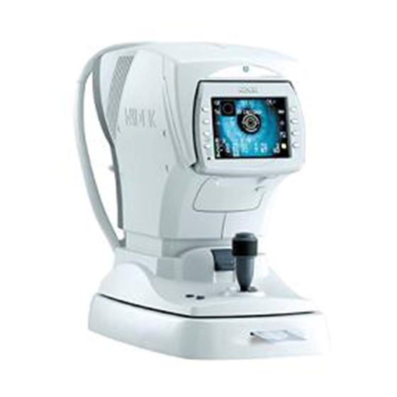
- Page 159 XAR17ARDA001E/E 8.3 Configuration Front view Function buttons LCD display Memory indicator Cover open button Printer cover Start button Joystick Eye Care card slot Locking lever Power switch 8 - 19...
- Page 160 XAR17ARDA001E/E Rear view Forehead rest Eye level marker Chinrest up/down buttons Measuring window Chinrest PD window 8 - 20...
- Page 161 XAR17ARDA001E/E 8.4 Labels * See the next page for the detailed ID labels. 8 - 21...
- Page 162 XAR17ARDA001E/E ID label list 8 - 22...
- Page 163 XAR17ARDA001E/E 8.5 Error Messages Error codes Contents Details ERR001 EEPROM error Defective data of the EEPROM ERR002 Clock error Defective IC data of the clock PD ERROR PD error Defective PD CCD, LED does not light up. ERR011 Time-out error (OUT) in characters Communication breaks during receiving data.
- Page 164 USB host class is improper. * For the details of ERR061 to ERR068 when the main board and driver board are combined, see the table below. Main board (30601-BA01) Unwritten AR-310A AR-330A AR-360A ARK-510A ARK-530A ARK-560A Unwriteen ERR061 ERR065 ERR065...
- Page 165 XAR17ARDA001E/E 8.6 Parameter List 8.6.1 AR-310A/AR-330A Parameter item Item JAPAN FOREIGN VON HOFF OCULUS CHINA STEP 0.25D 0.25D 0.25D 0.25D 0.25D 0.25D VERTEX D. 12.00mm 12.00mm 12.00mm 12.00mm 13.75mm 12.00mm AXIS STEP 1° 1° 1° 1° 1° 1° MEAS MODE Con.
- Page 166 XAR17ARDA001E/E 8.6.2 ARK-510A/ARK-530A Parameter item Item JAPAN FOREIGN VON HOFF OCULUS CHINA STEP 0.25D 0.25D 0.25D 0.25D 0.25D 0.25D VERTEX D. 12.00mm 12.00mm 12.00mm 12.00mm 13.75mm 12.00mm AXIS STEP 1° 1° 1° 1° 1° 1° MEAS MODE Con. Con. Con. Con....
- Page 167 XAR17ARDA001E/E 8.6.3 AR-360A Parameter item Item FOREIGN CHINA STEP 0.25D 0.25D 0.25D VERTEX D. 12.00mm 13.75mm 12.00mm AXIS STEP 1° 1° 1° MEAS MODE Con. Con. Con. AI MODE AR CONTINUE AR THUMBNAIL PRINT Manu. Manu. Manu. ECONO.PRINT PRINT&CLEAR PRINT DENCITY...
- Page 168 XAR17ARDA001E/E 8.6.4 ARK-560A Parameter item Item FOREIGN CHINA STEP 0.25D 0.25D 0.25D VERTEX D. 12.00mm 13.75mm 12.00mm AXIS STEP 1° 1° 1° MEAS MODE Con. Con. Con. AI MODE AR CONTINUE AR THUMBNAIL KM UNIT KM DISPLAY R1、R2 R1、R2 R1、R2 REF.INDEX 1.3375 1.3375...
- Page 169 XAR17ARDA001E/E 8.7 Jig List Part No. Name Part No. Name Part No. Name High-power spherical 30670-0100 model eye 30670-0200 Small pupil model eye 30670-0300 KM calibration jig 30670-1100 Joint jig 30670-1200 Reticle illumination jig 30670-1300 Reticle observation jig 30670-1400 Camera jig 30670-1500 Ring lens illumination jig Optical adjustment jig 30670-1600 Diffuser...
- Page 170 XAR17ARDA001E/E [This page is intentionally left blank.] 8 - 30...
Need help?
Do you have a question about the AR-360A and is the answer not in the manual?
Questions and answers