
Related Manuals for Nidek Medical ARK-530


Summary of Contents for Nidek Medical ARK-530
- Page 1 AUTO REF/KERATOMETER AUTO REF/KERATOMETER ARK-530A/ARK-510A ARK-530A/ARK-510A OPERATOR’S MANUAL OPERATOR’S MANUAL...
- Page 2 Original instructions NIDEK CO., LTD. : 34-14, Maehama, Hiroishi-cho, Gamagori, Aichi 443-0038, Japan (Manufacturer) Telephone: +81-533-67-6611 Facsimile: +81-533-67-6610 NIDEK CO., LTD. : 3F Sumitomo Fudosan Hongo Bldg., 3-22-5, Hongo, (Tokyo Office) Bunkyo-Ku, Tokyo 113-0033, Japan Telephone: +81-3-5844-2641 Facsimile: +81-3-5844-2642 NIDEK INCORPORATED : 47651 Westinghouse Drive, Fremont, California 94539, U.
-
Page 3: Safety Precautions
Use this device properly and safely. BEFORE USE, READ THIS MANUAL. This operator’s manual contains information necessary for the operation of the NIDEK AUTO REF/KERATOMETER Model ARK-530A/ARK-510A. This manual includes the operating procedures, safety precautions, and specifications. This manual is necessary for proper use. Especially, the safety precautions and operating procedures must be thoroughly understood prior to operation of the device. - Page 4 Usage precautions Safety of LED • The device is a Class 1 LED product in accordance with IEC60825-1: 1993+A1: CAUTION 1997+A2: 2001 and the LED used for the device is safe in expected use conditions including situations such as looking into the LED using an optical system. However, it is recommended to observe the following precautions when using the device: 1) Do not direct LED beams to human eyes when unnecessary.
- Page 5 • Avoid storing the device where it is exposed to rain or water, or poisonous gas or CAUTION liquid is present. Corrosion or malfunction of the device may occur. • Avoid installing the device where it is exposed to direct air-conditioning flow. Changes in temperature may result in condensation inside the device or adversely affect measurements.
- Page 6 • When the device is carried, two persons CAUTION should hold it at positions (A) and (B) (both right and left sides). Avoid lifting by the forehead rest or main body instead hold it by the bottom of the base. If only one person carries the device, or areas other than the base are used for lifting and the device falls, there is a...
- Page 7 During use • Before use, perform visual and operation checks. If abnormal conditions are CAUTION encountered, stop using the device. If the device is used under abnormal conditions, intended results may not occur. Also unexpected malfunctions or health hazards may occur due to improper measurement. •...
- Page 8 • Do not operate the LCD with wet hands. CAUTION Water seeping into the device may result in failure of the device. • There may be a few dead or constantly-lit pixels in your LCD. This does not represent failure of the LCD; This is due to the structure of the LCD. •...
- Page 9 • During installation and operation of the device, observe the following instructions CAUTION about EMC (electromagnetic compatibility): - Do not use the device simultaneously with other electronic equipment to avoid electro- magnetic interference with the operation of the device. - Do not use the device near, on, or under other electronic equipment to avoid electro- magnetic interference with the operation of the device.
- Page 10 { Patient environment The patient environment is the volume of space in which contact can occur between the patient and any part of the device (including connected devices) or between the patient and any other person(s) touching the device (including connected devices). Use devices that comply with IEC60601-1 in the patient environment.
-
Page 11: After Use
After use • This device uses a heat-sensitive printer paper. The paper degrades over time and the CAUTION printed characters may become illegible. If glue containing organic solvents or adhesives such as on adhesive tape comes in contact with the printer paper, the printed characters may become illegible. To keep the printed data for a long period of time, make copies of the printouts or write the measured results down. - Page 12 Maintenance • The manager of this device must perform maintenance every 6 months. CAUTION For details of the maintenance, contact NIDEK or your distributor. When the maintenance cannot be performed oneself, entrust them to NIDEK or your distributor. • Only service technicians properly trained by NIDEK can repair the device. NIDEK is not responsible for any accidents resulted from improper servicing.
-
Page 13: Table Of Contents
Table of Contents 1. BEFORE USE ........1 1.1 Outline of the Device . - Page 14 2.12.3 Printing parameter settings......... . . 73 2.13 Parameter Settings .
- Page 15 5.3.2 Optional accessories ..........125 6.
-
Page 17: Before Use
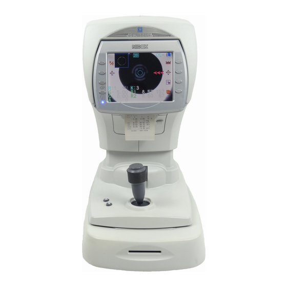
BEFORE USE Outline of the Device The NIDEK ARK-530A/ARK-510A is an auto ref/keratometer which contains both a refractometer and keratometer in one unit. The refractometer objectively measures refractive errors of sphere, cylinder, and axis for lenses that correct the patient’s vision into emmetropia. The keratometer measures the corneal curvature radius (corneal refractive power), principal meridian direction and corneal cylindrical power. -
Page 18: Principles
BEFORE USE Principles Principles Fine measurement beams are projected on the fundus of the patient’s eye by a projecting optical sys- tem and then computation is performed by capturing the reflected beams as a ring image to measure the refractive errors (SPH, CYL, AXIS) of the patient’s eye. Calculation is also performed by capturing the mire ring projected on the patient’s cornea as an image to measure the corneal curvature radius (refractive power) and the principal meridian direction. -
Page 19: Configuration
BEFORE USE Configuration Configuration { Front view Function buttons Memory indicator Start button Locking lever Joystick Power switch Eye Care card slot Cover open button Printer cover Function buttons Set the device and switch the screen. Functions assigned to the function buttons are displayed by icons on the screen. Two buttons on the left of the screen have unique functions when the measurement screen is displayed. - Page 20 BEFORE USE Configuration • Print button ( Pressing this button when the memory indicator is lit, prints out the measured data. Pressing the button when the memory indicator is not lit, advances printer paper. 5.7-inch LCD. Pulling the bottom of the display panel provides an adjustable viewing angle.
-
Page 21: Rear View
BEFORE USE Configuration { Rear view Forehead rest Eye level marker Measuring window Chinrest up/down button Chinrest PD window Forehead rest During measurement, the patient’s forehead should be gently rest against the forehead rest. Clean the chinrest for each patient. Measuring window Check the window cleanliness before measurement. - Page 22 BEFORE USE Configuration { Underside view Power inlet LAN port RS-232C ports USB-A port • Accessory equipment connected to the analog and digital interfaces must be certified CAUTION according to the representative appropriate national standards (for example, UL 1950 for Data Processing Equipment, UL 60601-1 for Medical Equipment, and CSA C22.2 No.
- Page 23 BEFORE USE Configuration RS-232C ports A communication cable is connected here to send/receive measured data to/ from a diagnostic device or such. Connectable devices RT-1200 series, RT-2100 series, RT-5100 LM-500, LM-970, LM-990/990A, LM-1000/1000P, LM-1200 To export the measured data to the refractor (RT), an external computer or such, (OUT) connect a communication cable to this side.
-
Page 24: Measurement Screen Layout
BEFORE USE Measurement Screen Layout Measurement Screen Layout The screen for AR (refractive error) and KM (corneal curvature radius) measurements is comprised of pages 1 to 3. Each page differs only in the touch icons displayed to the right of the screen. <When Page 1 is displayed>... - Page 25 BEFORE USE Measurement Screen Layout Minimum pupil circle Indicates the minimum pupil size measurable. If the pupil is smaller than this circle or eyelashes are on this circle, measurement may not be possible. Measured values Displays the latest measured results. Numeric values displayed to the right of “R: ”, “K: ”, “P: ”...
- Page 26 BEFORE USE Measurement Screen Layout Manual mode button ( Turns off both the auto tracking and auto shot functions (manual mode). The auto tracking icon and auto shot icon become blank ( ), indicating that these functions are turned off. Pressing the manual mode button returns to the state before the manual mode button was pressed.
- Page 27 BEFORE USE Measurement Screen Layout <When Page 2 is displayed> CS, PS, and PD data, ID, Eye Care card and CAT measurement mode icons are displayed on each page. Eye Care card icon ID icon CAT measurement mode CYL mode button icon PS (Pupil Size) indication SAG button...
- Page 28 BEFORE USE Measurement Screen Layout ID icon ( Displayed when the patient ID is entered. Entering a patient ID without an Eye Care card inserted replaces the ID icon with the ID number icon. Enter the patient ID using the optional barcode scanner or magnetic card reader.
- Page 29 BEFORE USE Measurement Screen Layout <When Page 3 is displayed> Vision comparison button Parameter button Vision comparison button ( Switches the current vision (uncorrected eye or that corrected by LM data) and the vision corrected by AR measurement. See “2.6 Vision Comparison Function” (page 53) for details on the comparison function mode. Parameter button ( Switches the screen to the PARAMETER SETTING screen.
-
Page 30: Labels
BEFORE USE Labels Labels Cautionary labels are provided on the device. If labels are curling up or characters fading and becoming barely legible, contact NIDEK or your autho- rized distributor. Indicates that the degree of protection against electric shock is of a Type B Applied Part. *The applied parts are the chinrest and the forehead rest (see in “1.4 Configuration”... - Page 31 BEFORE USE Labels { For countries other than the U.S.A. and Canada See “Before use” (page II) and “1.8 Before First Use” (page 18). [Underside view] See “Before use” (page II), “ During use” (page V), and “3 OPERATION WHEN PERIPHERAL DE- VICES ARE CONNECTED”...
- Page 32 BEFORE USE Labels { For the U.S.A. and Canada 30702-M803-C 30701-M803-C For the U.S.A. For Canada See “Before use” (page II) and “1.8 Before First Use” (page 18). [Underside view] USB-A RS232C See “Before use” (page II) and “1.8 See “Before use” (page II), “ During use” (page V), and “3 OPERATION Before First Use”...
-
Page 33: Checking Contents
BEFORE USE Checking Contents Checking Contents Unpack the contents from the shipping carton and check them. The following are included in the standard configuration. • Main body • Printer paper (3 rolls) • Power cord • Dust cover • Pack of chinrest paper •... -
Page 34: Before First Use
BEFORE USE Before First Use Before First Use Place the device on a stable table and connect a power cord to it. Place the main body on a stable table. Pull the main body fully to the side on which Power inlet the device is laid down, lock the main body to the base unit with the locking lever and lay the... - Page 35 BEFORE USE Before First Use Turn ON ( ) the power switch. The initial screen is displayed on the LCD and the device starts initializing. Initial screen (ARK-530A) Initial screen (ARK-510A) Confirm that the measurement screen is displayed. Measurement screen (ARK-530A) Measurement screen (ARK-510A) •...
- Page 36 BEFORE USE Before First Use { Please see here when you want to do like this. When Refer to the following. The details of the “MEASURING WINDOW CHECKING” “2.2.1 Checking the measuring window cleanliness at message displayed at device start-up need to be known. device start-up”...
- Page 37 BEFORE USE Before First Use Setting contents Parameters Sets how to start the vision comparison function 21. COMPARE SW Sets how to add ADD power, ADD power value in vision 23. ADD SW, 24. ADD SELECT comparison function Sets the operation method of printing 31.
- Page 38 BEFORE USE Before First Use...
-
Page 39: Operating Procedure
OPERATING PROCEDURE Operation Flow Turning on the device 2.2 Preparation for Measurement (see page 24) Turn on the power switch and set measurement conditions. Insert the Eye Care card. Prepare the patient. Measurement 2.3 AR (refractive error) and KM (corneal curvature radius) Measurements: AR/KM Mea- surement Mode (see page 36) 2.3.1 Cataract measurement mode (see page 45) 2.3.2 Measurement ring image display (see page 46) -
Page 40: Preparation For Measurement
OPERATING PROCEDURE Preparation for Measurement Preparation for Measurement Turn the power switch on ( Power switch The title screen is displayed and the device is initialized. Initial screen (ARK-530A) Initial screen (ARK-510A) Wait for a while until the screen switches to the measurement screen. When the power to the ARK-530A is turned on, the main body makes small back-and forth, side-to-side movements in order to determine the initial setting position for auto tracking. - Page 41 OPERATING PROCEDURE Preparation for Measurement The measurement screen is displayed. Measurement screen (ARK-530A) Measurement screen (ARK-510A) • If the power is turned on with no paper loaded, the error message “NO PAPER” appears. Supply printer paper. Perform checks before use. Perform the following checks before use.
- Page 42 OPERATING PROCEDURE Preparation for Measurement AR/KM measurement mode AR measurement mode KM measurement mode Pressing the button switches the measurement mode in the following order: AR/KMo ARo KMo AR/KMo..2 : Auto tracking function and auto shot function Specify the alignment (up-and-down and side-to-side directions) and focusing (forward-and-back- ward direction) methods and the method of triggering measurements.
- Page 43 OPERATING PROCEDURE Preparation for Measurement Manually align the device and bring the eye into focus. Measurement starts automatically when the eye is best aligned and focused. Manually align the device and bring the eye into focus. (No icon) Press the start button to start measurement. •...
- Page 44 OPERATING PROCEDURE Preparation for Measurement Confirm that the Eye Care card is properly inserted referring to the Eye Care card indication on the screen. Solid yellow display Accessing Eye Care card. Solid green display Blank Eye Care card inserted. Blinking green display Eye Care card with data inserted.
- Page 45 OPERATING PROCEDURE Preparation for Measurement 3) Instruct the patient to take off glasses or con- tact lenses and sit on a chair. 4) Have the patient place his/her chin on the chinrest as deeply as possible, and his/her forehead on the forehead rest lightly. 5) Adjust the height of the chinrest by the chin- Eye level marker rest up/down button (...
- Page 46 OPERATING PROCEDURE Preparation for Measurement Start measurement. For details of each measurement, see: “2.3 AR (refractive error) and KM (corneal curvature radius) Measurements: AR/KM Measurement Mode” (page 36) “2.4 AR (refractive error) Measurement: AR Measurement Mode” (page 48) “2.5 KM (corneal curvature radius) Measurement: KM Measurement Mode” (page 50) •...
- Page 47 OPERATING PROCEDURE Preparation for Measurement • Be careful of the following in handling the Eye Care card so that malfunction does not CAUTION occur. Be sure not to eject the Eye Care card while it is being accessed (yellow solid display Never bend or damage the card.
-
Page 48: Checking The Measuring Window Cleanliness At Device Start-Up
OPERATING PROCEDURE Preparation for Measurement 2.2.1 Checking the measuring window cleanliness at device start-up It is possible to set the parameter whether or not to check the measuring window for soiling before measurement. Activation of window check at device start-up varies according to the parameter setting. Parameter Description Selection of automatic window check as to whether or not the... -
Page 49: Switching To Manual Mode
OPERATING PROCEDURE Preparation for Measurement 2.2.2 Switching to manual mode It is possible to turn off both the auto tracking and auto shot functions (manual mode) by pressing the manual mode button during measurement. The manual mode button is used to turn off the auto tracking function according to the patient’s eye after starting measurement with the auto tracking function on. -
Page 50: Sleep Mode
OPERATING PROCEDURE Preparation for Measurement 2.2.3 Sleep mode The device goes into sleep mode automatically to save power if no button have been pressed for a certain period of time. The time that the device goes into sleep mode can be selected from 5 minutes, 10 minutes, 15 minutes, or NO (no sleep mode) (factory setting: 5 minutes). - Page 51 OPERATING PROCEDURE Preparation for Measurement { Shutoff before transporting the device Before the device is transported, put the device in packing mode. In packing mode, the measuring unit and chinrest are automatically set in preparation for transporta- tion. Turn the power switch off ( ) to shut off the device once.
-
Page 52: Ar (Refractive Error) And Km (Corneal Curvature Radius) Measurements: Ar/Km Measurement Mode
OPERATING PROCEDURE AR (refractive error) and KM (corneal curvature radius) Measurements: AR/KM Measurement Mode AR (refractive error) and KM (corneal curvature radius) Measurements: AR/KM Measurement Mode In AR/KM measurement mode, AR measurement and KM measurements are successively taken. When AR/KM measurement mode is selected, refractive errors (S, C and A) and corneal curvature radius (R1, R2) are displayed on the screen. - Page 53 OPERATING PROCEDURE AR (refractive error) and KM (corneal curvature radius) Measurements: AR/KM Manipulate the joystick to display the patient’s eye on the screen. By moving the joystick laterally, the main body moves right, left, forward and backward. By turning the upper part of the joystick, the main body moves up and down.
- Page 54 OPERATING PROCEDURE AR (refractive error) and KM (corneal curvature radius) Measurements: AR/KM Measurement Mode 2D auto tracking (ARK-530A) 1) Perform rough alignment and focusing by Up-and-down and side-to-side alignment: Auto manipulating the joystick to place in the working range of auto tracking. 2) When the device is placed within the working range of auto tracking, it automat- ically starts alignment.
- Page 55 OPERATING PROCEDURE AR (refractive error) and KM (corneal curvature radius) Measurements: AR/KM • If eyelashes obstruct the minimum pupil circle, correct AR measurement may not be possible. If the eyelid or eyelashes obstruct the mire ring, KM measurement may not be possible.
- Page 56 OPERATING PROCEDURE AR (refractive error) and KM (corneal curvature radius) Measurements: AR/KM Measurement Mode Too close to the patient’s eye Pull the joystick forward to move the main body away from the patient’s eye. Optimum condition Push the joystick backward to move the main body to- ward the patient’s eye.
- Page 57 OPERATING PROCEDURE AR (refractive error) and KM (corneal curvature radius) Measurements: AR/KM The way of fogging in the second and subsequent measurements varies according to the 4. MEAS MODE parameter setting. Fogging stays on throughout the measurement series. CON. This mode is useful for children who do not fixate their eyes very long. The patient’s view is fogged for each measurement even though the start NOR.
- Page 58 OPERATING PROCEDURE AR (refractive error) and KM (corneal curvature radius) Measurements: AR/KM Measurement Mode <KM measurement error messages> Error message Details Measurement is not possible because of blinking and slight movement of the eye. Instruct the patient not to blink or not to move the eye until (Blinking of the eye) measurement is completed.
- Page 59 OPERATING PROCEDURE AR (refractive error) and KM (corneal curvature radius) Measurements: AR/KM Measurement completes. • When AI mode is YES: When the specified number of KM measurements is performed, the measurement automatically completes. When the specified number of AR measurements is performed and the data is stable (no varia- tions), the measurement automatically completes.
- Page 60 OPERATING PROCEDURE AR (refractive error) and KM (corneal curvature radius) Measurements: AR/KM Measurement Mode A thumbnail of the measurement ring image is displayed when measurement is completed. If necessary, check the full screen ring image. See “2.3.2 Measurement ring image display” (page 46) for details on the ring image display. Measure the other eye in the same manner.
-
Page 61: Cataract Measurement Mode
OPERATING PROCEDURE AR (refractive error) and KM (corneal curvature radius) Measurements: AR/KM • Be careful of the following in handling the Eye Care card so that malfunction does CAUTION not occur. Be sure not to eject the Eye Care card while it is being accessed (yellow solid display Never bend or damage the card. -
Page 62: Measurement Ring Image Display
OPERATING PROCEDURE AR (refractive error) and KM (corneal curvature radius) Measurements: AR/KM Measurement Mode 2.3.2 Measurement ring image display The ARK-530A/ARK-510A projects measurement beams on the patient’s fundus and computation is performed by capturing the reflected beams as a ring image to measure the refractive errors of the patient’s eye. -
Page 63: Km Peripheral Measurement
OPERATING PROCEDURE AR (refractive error) and KM (corneal curvature radius) Measurements: AR/KM 2.3.3 KM peripheral measurement Setting the 15. PERIPHERAL parameter to YES allows the operator to measure the peripheral four points as well as the mire ring in the center (KM measurement). Measurement area KM measurement (mire ring) 3.3 mm (for corneal curvature radius of 7.7 mm) in diameter... -
Page 64: Ar (Refractive Error) Measurement: Ar Measurement Mode
OPERATING PROCEDURE AR (refractive error) Measurement: AR Measurement Mode AR (refractive error) Measurement: AR Measurement Mode Perform AR measurement in the same manner as AR/KM measurement mode. KM (corneal curvature radius) measurement is not performed; KM-measured data is not displayed on the screen. - Page 65 OPERATING PROCEDURE AR (refractive error) Measurement: AR Measurement Mode • If the device gets out of alignment and focus during measurement, the measurement is interrupted. If the measurement is retried, the measured results are added to the former results and saved. •...
-
Page 66: Km (Corneal Curvature Radius) Measurement: Km Measurement Mode
OPERATING PROCEDURE KM (corneal curvature radius) Measurement: KM Measurement Mode KM (corneal curvature radius) Measurement: KM Measurement Mode Perform KM measurement in the same manner as AR/KM measurement mode. AR (refractive error) measurement is not performed; AR-measured data is not displayed on the screen. - Page 67 OPERATING PROCEDURE KM (corneal curvature radius) Measurement: KM Measurement Mode KM measurement completes. The latest values are always displayed on the screen. • If the device gets out of alignment and focus during measurement, the measurement is interrupted. If the measurement is retried, the measured results are added to the former results and saved.
- Page 68 OPERATING PROCEDURE KM (corneal curvature radius) Measurement: KM Measurement Mode When the specified number of KM measurements have not been obtained, “<<KM?>>” is displayed on the screen. When the specified number of KM peripheral measurements have not been obtained, “<<PERI?>>” is displayed on the screen.
-
Page 69: Vision Comparison Function
OPERATING PROCEDURE Vision Comparison Function Vision Comparison Function A vision comparison function allows the patient to compare the current vision (uncorrected eye vision or that corrected by LM data) with the vision corrected by AR measurement. By changing the distance to the chart, the patient can also experience the vision for near distance. - Page 70 OPERATING PROCEDURE Vision Comparison Function Press the vision comparison button again to present the uncorrected eye vision (or that corrected by LM data). Blinking SE of (or LM) indicates the uncorrected eye vision (or that corrected by LM data) at the moment. Blinking shows which vision is presented at the moment.
- Page 71 OPERATING PROCEDURE Vision Comparison Function • Regardless of the vision (AR measurement, uncorrected eye, LM data) presented, the vision for near distance is presented by pressing the near button 2) If necessary, switch to the vision with addition power. Pressing the ADD button with “<40cm>”...
- Page 72 OPERATING PROCEDURE Vision Comparison Function { Operation on vision comparison screen Measurement screen Distance vision Distance vision Near vision Near vision Near vision with ADD power Near vision with ADD power Uncorrected eye vision or that Objectively corrected vision (AR corrected by LM data measurement) Vision comparison function...
-
Page 73: Importing Lm Data
OPERATING PROCEDURE Vision Comparison Function 2.6.1 Importing LM Data Import LM data (data of glasses that the patient uses) to the ARK-530A/ARK-510A by inserting an Eye Care card with the LM data written. The imported data is used in order to present the vision with his or her glasses instead of uncorrected eyes using the vision comparison function. -
Page 74: Cs (Corneal Size) Measurement
OPERATING PROCEDURE CS (Corneal Size) Measurement CS (Corneal Size) Measurement Press the CS/PS/PD button to enter CS measurement mode. “<<CORNEAL SIZE>>”, guide lines and “START SW: CAPTURE” are displayed on the screen. Pressing the CS/PS/PD button switches the mode in the following order: AR/KMo CSo PSo PDo CSo ... - Page 75 OPERATING PROCEDURE CS (Corneal Size) Measurement Press the right button or left button align the guide line with the left end of the patient’s cornea. Move the guide line to the left end of the pa- tient’s cornea. Press the start button to confirm the measure- ment.
-
Page 76: Ps (Pupil Size) Measurement
OPERATING PROCEDURE PS (Pupil Size) Measurement PS (Pupil Size) Measurement This is the procedure to measure the pupil size (PS). To measure PS continuing from CS (Corneal Size) measurement, start from Step 5. • If the mode is switched to PS measurement mode from when a still image is displayed on the CS (Corneal SIze) measurement screen, a still image is displayed. - Page 77 OPERATING PROCEDURE PS (Pupil Size) Measurement • When the right button or left button has never been pressed, the measured values are not displayed. Start measurement again from capturing. Press the right button or left button align the guide line on the right of the patient’s pupil.
-
Page 78: Pd (Pupillary Distance) Measurement
OPERATING PROCEDURE PD (Pupillary Distance) Measurement PD (Pupillary Distance) Measurement 2.9.1 Auto PD measurement When the 63. AUTO PD parameter is set to YES, at the moment where measurement of both eyes is completed, PD measurement is also completed and then the PD value is displayed. - Page 79 OPERATING PROCEDURE PD (Pupillary Distance) Measurement After proper alignment of the right eye and left eye, press the start button each time. To measure monocular PD at the same time as the binocular PD, press the start button every after proper alignment of the right-eye, center, and the left-eye.
-
Page 80: Sagittal Radius Measurement
OPERATING PROCEDURE Sagittal Radius Measurement 2.10 Sagittal Radius Measurement Set the 81. SAGITTAL parameter to YES. • If the 31. PRINT parameter has been set to AUTO, set it back to MANUAL. As soon as KM measurements are obtained, the SAG icon is displayed. - Page 81 OPERATING PROCEDURE Sagittal Radius Measurement Press the start button. The sagittal radius of the right of the cornea is measured. “L” changes to “ ” and then “R” starts blinking. • If the measurement is erroneous, “L” changes to “E”. In such cases, repeat the measurement by pressing the start button.
- Page 82 OPERATING PROCEDURE Sagittal Radius Measurement Sample printout The following are sample printouts for the left eye and explanations of each data item. <Sample printout 1> Sample printout - When the 83. SAGIT PRINT parameter is set to ALL < SAGITTAL > = Sagittal radius on each side SUP.
-
Page 83: Measuring Hard Contact Lenses
OPERATING PROCEDURE Measuring Hard Contact Lenses 2.11 Measuring Hard Contact Lenses To measure hard contact lenses, use the provided CL holder. The contact lens holder is incorporated in the spherical model eye. The CL holder is integral with the spherical model eye. Fill the concave top of the CL holder with water. - Page 84 OPERATING PROCEDURE Measuring Hard Contact Lenses Place the model eye/CL holder with the sur- face of the contact lens to be measured facing toward the measuring window and insert the fixing pins. Select the KM measurement mode and measure the lens in the same manner as KM measurement.
-
Page 85: Printing
OPERATING PROCEDURE Printing 2.12 Printing 2.12.1 Printing measured data Measured data is printed out by pressing the print button after measurement. Printing completes with paper still attached so that it does not fall. Tear off the paper to detach. • When the 31. PRINT parameter is set to AUTO, printing starts automatically when the measurements of both eyes complete. - Page 86 OPERATING PROCEDURE Printing <Sample printout 2> Patient No. Patient ID*1 Space for name and sex Date and time of measurement Vertex distance*2 Near working distance*3 AR measurement, Confidence index*4 S = Spherical powers C = Cylindrical powers A = Cylinder axis AR median values*5 SE value*6 Eyeprint*7...
- Page 87 OPERATING PROCEDURE Printing • Items with “ ” indicate whether or not to print according to parameter settings. See PRINT1 to PRINT3 of “2.13.1 Parameter tables” (page 77). Patient ID The patient ID scanned by the optional barcode scanner or magnetic card reader Vertex distance The distance between the corneal vertex to the posterior surface of spectacle lenses Near working distance...
-
Page 88: Eyeprint
OPERATING PROCEDURE Printing Trial lens data Based on the AR median values (or the latest values when AR median values have not been obtained), the cylinder reading direction is automatically converted so that a spherical trial lens has lower power as reference data. Contact lens conversion value The AR median values (or the latest values when AR median values have not been obtained) are converted into CL values, letting the vertex distance (VD) be 0 mm. -
Page 89: Printing Parameter Settings
OPERATING PROCEDURE Printing 2.12.3 Printing parameter settings The current parameter settings, set time, comments, and maintenance program versions are printed out. Press and hold the parameter button for about a second. The PARAMETER SETTING screen is displayed. The parameter No. and parameter names are displayed. -
Page 90: Parameter Settings
OPERATING PROCEDURE Parameter Settings 2.13 Parameter Settings The ARK-530A/ARK-510A is provided with parameters that set various functions according to the user’s usage pattern. The procedure for checking and changing the parameter settings is explained. Press and hold the parameter button about a second. - Page 91 OPERATING PROCEDURE Parameter Settings Press the execute button to switch to the [PRINT1] screen. Parameters and their settings are displayed. A parameter that is being selected is highlighted. PRINT1 screen Press the up/down button to select a parameter to be changed. Move the highlight.
- Page 92 OPERATING PROCEDURE Parameter Settings To change the page of parameter: Page up button Displays the previous page. Page down button Displays the next page. Repeat Steps 4 to 5 to change the desired parameter settings. To finish setting the parameters, press the exit button The set parameter settings are saved even after power-off.
-
Page 93: Parameter Tables
OPERATING PROCEDURE Parameter Settings 2.13.1 Parameter tables [AR (AR measurement)] * Underlined options indicate factory settings. Parameter Settings STEP 0.01D / 0.12D / 0.25D VERTEX D. 0.00mm / 10.50mm / 12.00mm / 13.75mm / 15.00mm / 16.50mm AXIS STEP 1°/ 5° MEAS MODE CON. - Page 94 OPERATING PROCEDURE Parameter Settings 7 : AR THUMBNAIL Selects whether to display the thumbnail screen of the measurement ring image during AR measure- ment. When YES is selected, a thumbnail of the measurement ring image is displayed to the left of the screen after AR measurement is complete.
- Page 95 OPERATING PROCEDURE Parameter Settings [COMPARE (Vision comparison function)] * Underlined options indicate factory settings. Parameter Settings COMPARE SW AUTO / MANUAL / NO COMPARE(AR) SE / -SPH ADD SW YES / NO ADD SELECT 1.50D / 1.75D / 2.00D 21 : COMPARE SW (comparison function button) Selects how to enter the vision comparison function screen.
- Page 96 OPERATING PROCEDURE Parameter Settings [PRINT1 (Print setting 1)] * Underlined options indicate factory settings. Parameter Settings PRINT MANUAL / AUTO / NO ECONO. PRINT YES / NO PRINT&CLEAR YES / NO PRINT DENSITY LOW / MIDDLE / HIGH PATIENT NO. YES / NO SET PATIENT NO.
- Page 97 OPERATING PROCEDURE Parameter Settings 38 : DATE FORMAT (date format) Selects the format of date. Y/M/D Year, Month, Date M/D/Y Month, Date, Year D/M/Y Date, Month, Year No printing 39 : PRINT COMMENT Selects whether to print comments. [PRINT2 (Print setting 2)] * Underlined options indicate factory settings.
- Page 98 OPERATING PROCEDURE Parameter Settings 44 : ERROR DATA Selects whether to display and print erroneous data obtained during AR measurement. When YES is selected and the measured data is erro- neous, the data is displayed in yellow and “Err” is printed before the measured data.
- Page 99 OPERATING PROCEDURE Parameter Settings [PRINT3 (Print setting 3)] * Underlined options indicate factory settings. Parameter Settings SE PRINT YES / NO EYE PRINT YES / NO TL PRINT YES / NO CL PRINT YES / NO NEAR PD PRINT YES / NO 35 to 70 cm (5 cm increments) WORKING D.
- Page 100 OPERATING PROCEDURE Parameter Settings [FUNCTION (Various functions)] * Underlined options indicate factory settings. Parameter Settings WINDOW CHECK YES / NO / DAY TRACKING SW TRC/ASHOT / ASHOT ON / ASHOT OFF AUTO PD YES / NO SLEEP 5MIN / 10MIN / 15MIN / NO BEEP LOW / HIGH / NO LCD BRIGHTNESS...
- Page 101 OPERATING PROCEDURE Parameter Settings 63 : AUTO PD (auto PD measurement) Selects whether to measure PD during AR measurement and/or KM measurement. (This function is activated only when both eyes are measured.) 64 : SLEEP (sleep time) Selects the auto-sleep function. The LCD is shut down automatically after a set period during which no buttons have been pressed.
- Page 102 OPERATING PROCEDURE Parameter Settings [COMMUNICATION (Communication function)] * Underlined options indicate factory settings. Parameter Settings I/F MODE NIDEK / NCP10 I/F FORMAT ALL / SHORT BAUD-RATE 1200 / 2400 / 4800 / 9600 BIT LENGTH 7 / 8 CR CODE YES / NO LM DATA PRINT YES / NO...
- Page 103 OPERATING PROCEDURE Parameter Settings [SAGITTAL (Sagittal radius measurement function)] * Underlined options indicate factory settings. Parameter Settings SAGITTAL YES / NO SAGIT AXIS AXIS / FIX SAGIT PRINT ALL / SHORT 81 : SAGITTAL (sagittal radius measurement) Selects whether to measure sagittal radius after KM measurement in R/K mode or K mode. 82 : SAGIT AXIS Selects whether to convert the sagittal radius measurement for the axis of the steepest meridian which has been obtained by KM measurement.
- Page 104 OPERATING PROCEDURE Parameter Settings [READER (barcode / magnetic card reader function)] * Underlined options indicate factory settings. Parameter Settings READER START 1 to 250 READER LENGTH 1 to 14 101 : READER START (position to start reading) Sets the position to start reading ID when the magnetic card reader is used. Control codes are included in the number of characters.
- Page 105 OPERATING PROCEDURE Parameter Settings [NETWORK (LAN communication function)] * Underlined options indicate factory settings. Parameter Settings NETWORK YES / NO / ACK DHCP YES / NO 0 to 255, 0 to 255, 0 to 255, 0 to 255 192.168. 0. 30) Factory setting: 0 to 255, 0 to 255, 0 to 255, 0 to 255 MASK...
- Page 106 OPERATING PROCEDURE Parameter Settings 113 : IP (IP address) Input the IP address. * When the 112. DHCP parameter is set to YES, this parameter cannot be changed. (The subnet mask obtained from the DHCP server is displayed. When “0. 0. 0. 0” is displayed, IP has not been obtained from the DHCP).
-
Page 107: Setting And Confirming The Network Communication Function (Lan)
OPERATING PROCEDURE Parameter Settings 2.13.2 Setting and confirming the network communication function (LAN) Set the 113. IP to 119. FOLDER parameters necessary for connecting to computer via network (LAN) in the procedure below. { Setting 113. IP and 114. MASK parameters The input procedure for the 113. - Page 108 OPERATING PROCEDURE Parameter Settings Press the up button or down button select “113. IP”. Press the execute button to display the IP screen The screen changes to the IP screen. Change the IP address. Moves the cursor. Press , or start button. Press or rotate the joystick Decreases the input value.
- Page 109 OPERATING PROCEDURE Parameter Settings { Setting 115. USER to 119. FOLDER parameters The input procedure for the 115. USER parameter is explained. The procedure for the 116. PASS- WORD to 119. FOLDER parameters are the same. Press the up button or down button select “115.
- Page 110 OPERATING PROCEDURE Parameter Settings After changing the user name, press the exit but- A message to confirm the setting is displayed. Select YES or NO. Press , or rotate the joystick to select YES or NO. Press the execute button or start button to set YES or NO.
-
Page 111: Setting The Date And Time
OPERATING PROCEDURE Parameter Settings 2.13.3 Setting the date and time When the date and time of the printout is not correct, set the correct date and time. • If the device is not turned on for 3 weeks, the date and time may become incorrect. Press and hold the parameter button about a second. - Page 112 OPERATING PROCEDURE Parameter Settings Press the up button or down button move the highlight to an item to be changed. Press the right button or the left button to change the setting. Increases the number. Right button Decreases the number. Left button To change the time format: Change the time format between the 24-hour and 12-hour.
-
Page 113: Entering Comments
OPERATING PROCEDURE Parameter Settings 2.13.4 Entering comments Comments to be printed can be changed (factory setting: “NIDEK ARK-530A”/ “NIDEK ARK-510A”). Press and hold the parameter button about a second. The PARAMETER SETTING screen is dis- played. Press the down button to select “COMMENT SET”. - Page 114 OPERATING PROCEDURE Parameter Settings Enter comments with the following buttons. After moving the cursor of the character list to the desired character, press the OK button to confirm its entry. The following buttons are available: Moves the character to be input (cursor) in the character list field to the left. Moves the character to be input (cursor) in the character list field to the right.
-
Page 115: Operation When Peripheral Devices Are Connected
OPERATION WHEN PERIPHERAL DEVICES ARE CONNECTED The ARK-530A/ARK-510A exports data to an external device such as the NIDEK motorized refractor (hereafter referred to as RT) and computer. It also imports data from the NIDEK lensmeter (hereafter referred to as LM). •... -
Page 116: Rs-232C Connection
OPERATION WHEN PERIPHERAL DEVICES ARE CONNECTED Connecting to the NIDEK Motorized Refractor (RT) or Computer 3.1.2 RS-232C connection { Connecting procedure Connect the RT (or a computer) to the data output port ( ) of the ARK-530A/ARK- 510A via a communication cable (optional). Connect the cable with the device on its side. -
Page 117: Network Connection (Lan)
OPERATION WHEN PERIPHERAL DEVICES ARE CONNECTED Connecting to the NIDEK Motorized 3.1.3 Network connection (LAN) { Connecting procedure Connect a computer to the LAN port on the underside of the ARK-530A/ARK-510A via a LAN cable. Connect the cable with the device on its side. LAN cable Computer The ARK-530A/ARK-510A and the parameters are set under approval of the network admin-... -
Page 118: Connecting To The Nidek Auto Lensmeter (Lm)
OPERATION WHEN PERIPHERAL DEVICES ARE CONNECTED Connecting to the NIDEK Auto Lensmeter (LM) Connecting to the NIDEK Auto Lensmeter (LM) 3.2.1 Outline The ARK-530A/ARK-510A imports data measured with the NIDEK lensmeter, and prints the LM data (lensmeter readings). It also exports the LM data to the connected RT. (The lensmeter provided with this function is needed.) Connectable devices: LM-500, LM-970, LM-990/990A, LM-1000/1000P, LM-1200 The LM data transmitted to the RT is used as previous eyeglass lens values in the subjective test. -
Page 119: Operating Procedure
OPERATION WHEN PERIPHERAL DEVICES ARE CONNECTED Connecting to the NIDEK Auto Lensmeter Communication cable (optional) To LM Ferrite cores (optional) To RT 3.2.3 Operating procedure After lens measurement with the LM, press the print button on the LM. The ARK-530A/ARK-510A receives lensmeter readings from the LM. •... -
Page 120: Reading Patient Id
OPERATION WHEN PERIPHERAL DEVICES ARE CONNECTED Reading Patient ID Reading Patient ID Read patient ID using a barcode scanner or magnetic card reader. The read patient ID numbers are printed on the ARK-530A/ARK-510A as well as the measured data. • Although patient ID can be read before or after measurement, it is advisable to read it before printing the measured data. -
Page 121: Operating Procedure Of Barcode Scanner
OPERATION WHEN PERIPHERAL DEVICES ARE CONNECTED Reading Patient ID 3.3.2 Operating procedure of barcode scanner Place the scanner window over the barcode. Scanner window Trigger button Press the trigger button. Confirmation LED The scanner window blinks in red and the bar- code is read. -
Page 122: Operating Procedure Of Magnetic Card Reader
OPERATION WHEN PERIPHERAL DEVICES ARE CONNECTED Reading Patient ID 3.3.3 Operating procedure of magnetic card reader Swipe the card with the magnetic card reader A beep sounds and the green LED goes out. When the card has been read successfully, Card the LED lights up. -
Page 123: Maintenance
MAINTENANCE Troubleshooting In the event that the device does not work correctly, correct the problem according to the following table before contacting NIDEK or your authorized distributor. Symptom Remedy • The power cord may not be correctly connected. The LCD does not turn on. Reconnect it securely. - Page 124 MAINTENANCE Troubleshooting Symptom Remedy • The auto tracking function or auto shot function may not have been turned on. Turn them on with the auto button • Room illumination may be reflecting on the cornea. Change the location and try measurement again. •...
-
Page 125: Error Messages And Countermeasures
MAINTENANCE Error Messages and Countermeasures Error Messages and Countermeasures If one of the following error codes is displayed on the screen or printed out, follow the suggestions in the cause and countermeasure column. The error code, detailed indications and serial number of your device are helpful in proper servicing. Error code Cause and countermeasure •... - Page 126 MAINTENANCE Error Messages and Countermeasures Error code Cause and countermeasure • Error related to control signals for communication (input port) ERR021 Ensure that the communication cable is properly connected to the input port. • Also ensure that the communication parameters are properly set. •...
- Page 127 MAINTENANCE Error Messages and Countermeasures Error code Cause and countermeasure • Error related to the motor sensor ERR101 Malfunction of the motor or sensor is probable. • Shut off the device and contact NIDEK or your authorized distributor. • Error related to the temperature sensor Malfunction of the electric circuit board or temperature sensor on the electric circuit board is ERR111 probable.
- Page 128 MAINTENANCE Error Messages and Countermeasures • Error related to the computer name ERR754 Computer with the specified name does not exist. • Check the connection of the LAN cable. Or check that the specified PC name is correct. • Error related to the read-only attribute ERR755 The shared folder in the computer is designated as read-only and cannot be written to.
-
Page 129: Replacing Printer Paper
MAINTENANCE Replacing Printer Paper Replacing Printer Paper When a red line appears on the side of printer paper, it means that paper is running short. In such a case, stop using the printer and replace printer paper with new one. •... - Page 130 MAINTENANCE Replacing Printer Paper Insert new printer paper. Load printer paper as shown in the picture on the right. Set printer paper so that its end is exposed from the cover. • If the roll is loaded in such a way that paper becomes upside down, it is not possible to print data out.
-
Page 131: Fixing Chinrest Paper
MAINTENANCE Fixing Chinrest Paper Fixing Chinrest Paper Disconnect the two fixing pins from the chinrest. Remove a proper number of chinrest papers from the pack. The whole pack of chinrest paper cannot be fixed. Be sure to fix a stack with a thickness of 6 mm of less. -
Page 132: Checking The Ar/Km Measurement Accuracy
MAINTENANCE Checking the AR/KM Measurement Accuracy Checking the AR/KM Measurement Accuracy To check the accuracy of measured data, use the provided spherical model eye for R/K measurement. The spherical model eye is incorporated with a contact lens holder. Remove the two fixing pins and remove the stack of chinrest paper from the chinrest. - Page 133 MAINTENANCE Checking the AR/KM Measurement Accuracy { Values marked on the labels of the spherical model eye Vertex distance Diopter (Unit: D) Corneal curvature radius (Unit: mm) • When the vertex distance is set to a value other than 12 mm (US: 13.75 mm), set the 2. VERTEX D.
-
Page 134: Cleaning
MAINTENANCE Cleaning Cleaning When the cover or panel of the device becomes dirty, clean it with a soft cloth. For severe stains, soak the cloth in a neutral detergent, wiring well, and wipe. Finally dry with a soft, dry cloth. •... - Page 135 MAINTENANCE Cleaning Check if the window is cleaned using a penlight. If not, clean it again with new cleaning paper. Apply light with a penlight and change the view angle to check the dirt clearly. Measuring window • When the 61. WINDOW CHECK parameter is set to YES or DAY, the measuring window is checked whether it is clean at device start-up.
-
Page 136: Cleaning The Printer
MAINTENANCE List of Replacement Parts 4.6.2 Cleaning the printer After repeated usage, the paper slot of the auto cutter of the printer may become soiled with powdery paper. If the powdery paper settles, malfunction of the auto cutter may result. Check the auto cutter before using the device. -
Page 137: Specifications And Accessories
SPECIFICATIONS AND ACCESSORIES Classifications [Form of protection against electrical shock] Class I The ARK-530A/ARK-510A is classified as a Class I device. A Class I is a device in which the protection against electric shock does not rely on basic insulation only, but which includes an additional safety precaution in such a way that means are provided for the connection of the device to the protective (ground) conductor in the fixed wiring of the installation in such a way that accessible metal parts can not become live in the event of a failure in the basic insulation. -
Page 138: Specifications
SPECIFICATIONS AND ACCESSORIES Specifications Specifications { Measurement of refractive error (AR measurement) • Spherical power (S) -30.00 to +25.00 D (VD = 12 mm) 0.01/ 0.12/ 0.25 D increments • Cylindrical power (C) 0 to ±12.00 D 0.01/ 0.12/ 0.25 D increments •... - Page 139 SPECIFICATIONS AND ACCESSORIES Specifications • Cylinder axis (A) 0 to 180q 1q/ 5q increments I3.3 mm (for mire ring/ corneal curvature radius of 7.7 mm) • KM measurable area I6.0 mm (for four points/ corneal curvature radius of 7.7 mm) •...
-
Page 140: Other Functions
SPECIFICATIONS AND ACCESSORIES Specifications { Other functions • Alignment/observation method 5.7-inch color LCD • Printer Thermal line printer with auto cutter Width 58 mm • Interface connectors RS-232C: Two ports (IN/OUT) USB: One port LAN: One port { Dimensions and mass •... -
Page 141: Standard Configuration
SPECIFICATIONS AND ACCESSORIES Standard Configuration Standard Configuration 5.3.1 Standard accessories • Printer paper 3 rolls • Power cord 1 unit • Dust cover 1 unit • Pack of chinrest paper 1 unit • Fixing pins for chinrest paper 2 units •... - Page 142 SPECIFICATIONS AND ACCESSORIES Standard Configuration...
-
Page 143: Emc (Electromagnetic Compatibility)
EMC (ELECTROMAGNETIC COMPATIBILITY) The device complies with the International Electrotechnical Commission standards (IEC 60601-1-2: 2007) for electromagnetic compatibility as listed in the tables below. Follow the guidance in the tables for use of the device in an electromagnetic environment. EMC (IEC 60601-1-2: 2007) Guidance and manufacturer's declaration - electromagnetic emissions The device is intended for use in the electromagnetic environment specified below. - Page 144 EMC (ELECTROMAGNETIC COMPATIBILITY) Guidance and manufacturer's declaration - electromagnetic immunity The device is intended for use in the electromagnetic environment specified below. The customer or the user of the device should assure that it is used in such an environment. Immunity test IEC 60601 test level Compliance level...
- Page 145 EMC (ELECTROMAGNETIC COMPATIBILITY) Guidance and manufacturer's declaration - electromagnetic immunity The device is intended for use in the electromagnetic environment specified below. The customer or the user of the device should assure that it is used in such an environment. Immunity test IEC 60601 test level Comliance level...
- Page 146 EMC (ELECTROMAGNETIC COMPATIBILITY) Recommended separation distances between portable and mobile RF communications equipment and the device The device is intended for use in an electromagnetic environment in which radiated RF disturbances are controlled. The customer or the user of the device can help prevent electromagnetic interference by maintaining a minimum distance between portable and mobile RF communications equipment (transmitters) and the device as recommended below, according to the maximum output power of the communications equipment.
-
Page 147: Glossary
GLOSSARY AI mode Measurement automatically completes after over the specified number of measurements if the data is stable without variations in the AR measurement. When unstable data is included, additional measurements are necessary until stable data is obtained. AR median value The spherical equivalent (SE) value is obtained from respective data. - Page 148 GLOSSARY Fogging Blurs the patient’s view to prevent focus in order to eliminate accommodation. KM median value The middle value of measurements which are arranged in order in the computer. The latest values are selected when the measured data is two or less. Limit indicator When the main body moves out of the working range of auto tracking, the limit indicator (arrows) is displayed on the screen.
-
Page 149: Index
INDEX AI mode ........131 KM median value . - Page 150 INDEX Target ........8 Trial lens data .
Need help?
Do you have a question about the ARK-530 and is the answer not in the manual?
Questions and answers
we are experiencing the error "PD ERR". we are unable to measure/capture AR for Left eye, only the right. we tried to adjust auto tracking to no avail. the manual says to make sure the PD measuring window is not blocked and contact Nidek. please advise
The "PD ERR" error on the Nidek Medical ARK-530 indicates an issue with measuring the patient's pupillary distance. Possible causes include:
- The PD measuring window is blocked.
- The patient blinked during measurement.
- The eyelid or eyelashes obstruct the measurement.
- The pupil is too small for measurement.
- The data exceeds the measurable limit.
- The measuring window is dirty.
To resolve the issue when unable to measure the left eye:
1. Ensure the PD measuring window is not blocked.
2. Instruct the patient not to blink during measurement.
3. Ask the patient to open their eye wider. If needed, gently lift the eyelid without pressing on the eyeball.
4. If the pupil is too small, have the patient sit in a dark room to allow dilation.
5. Check if the data is within the measurable range.
6. Clean the measuring window.
If the issue persists after these steps, further troubleshooting may be required.
This answer is automatically generated