Table of Contents
Advertisement
NIDEK CO., LTD.
(Manufacturer)
NIDEK CO., LTD
(Tokyo Office)
NIDEK INCORPORATED
(United States Agent)
NIDEK SOCIETE ANONYME
(Authorized Representative)
: 34-14, Maehama, Hiroishi-cho, Gamagori, Aichi 443-0038, Japan
Telephone: (0533) 67-6611
Facsimile: (0533) 67-6610
: 6th Floor, Takahashi Bldg., No.2, 3-chome, Kanda-jinboucho
Chiyoda-ku, Tokyo 101-0051, Japan
Telephone: (03) 3288-0571
Facsimile: (03) 3288-0570
Telex: 2226647 NIDEK J
: 47651 Westinghouse Drive, Fremont, California 94539, U. S. A.
Telephone: (510) 226-5700
Facsimile: (510) 226-5750
: Europarc 13, rue Auguste Perret, 94042 CRETEIL, France
Telephone: (01) 49 80 97 97
Facsimile: (01) 49 80 32 08
March 2006
32163-P902E
Printed in JAPAN
Advertisement
Table of Contents

Related Manuals for Nidek Medical ARK-730A


Summary of Contents for Nidek Medical ARK-730A
- Page 1 NIDEK CO., LTD. : 34-14, Maehama, Hiroishi-cho, Gamagori, Aichi 443-0038, Japan (Manufacturer) Telephone: (0533) 67-6611 Facsimile: (0533) 67-6610 NIDEK CO., LTD : 6th Floor, Takahashi Bldg., No.2, 3-chome, Kanda-jinboucho (Tokyo Office) Chiyoda-ku, Tokyo 101-0051, Japan Telephone: (03) 3288-0571 Facsimile: (03) 3288-0570 Telex: 2226647 NIDEK J NIDEK INCORPORATED : 47651 Westinghouse Drive, Fremont, California 94539, U.
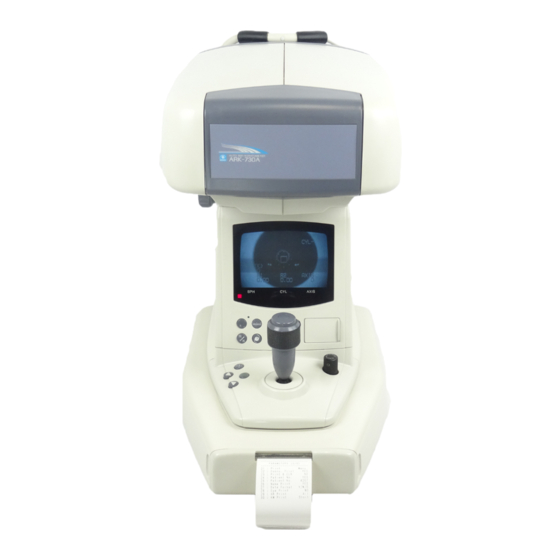
- Page 2 NIDEK AUTO REF/KERATOMETER Model ARK-730A OPERATOR’S MANUAL...
- Page 3 BEFORE USE OR MAINTENANCE, READ THIS MANUAL. This Operator’s Manual contains information necessary for the operation of the NIDEK AUTO REF/KERATOMETER Model ARK-730A. This manual includes the operating procedures, safety precautions, specifications, and information about accessories and maintenance. The device complies with ISO 10342 (Ophthalmic devices—Eye Refractometers). IEC 60601-1 and UL 60601-1 standards are applied in this manual.
-
Page 4: Table Of Contents
Table of Contents Page § 1 INTRODUCTION ......................1-1 1.1 Outline of the Device ....................1-1 1.2 Indications for Use ....................1-1 1.3 Classifications ......................1-1 1.4 Symbol Information ....................1-3 § 2 SAFETY ......................... 2-1 2.1 Cautions in Storage, Transportation and Installation ..........2-1 2.2 Connecting the Device to a Wall Outlet and Handling the Power Cord .... - Page 5 Page § 8 VARIOUS SETTINGS ....................8-1 8.1 Setting Parameters ....................8-1 8.2 Setting Date and Time ..................... 8-10 8.3 Entering Comments ....................8-11 8.4 Measuring Hard Contact Lenses ................8-14 § 9 TROUBLESHOOTING GUIDE ................. 9-1 § 10 MAINTENANCE ......................10-1 10.1 Replacing the Printer Paper ..................
- Page 6 [This page is intentionally left blank.]...
-
Page 7: Introduction
INTRODUCTION 1.1 Outline of the Device The ARK-730A is an auto ref/keratometer which contains both a refractometer and a keratometer in one unit. The refractometer objectively measures the refractive errors of sphere, cylinder, and axis for the lens that corrects the patient’s vision into emmetropia. The keratometer measures the corneal curvature radius, corneal refractive power, corneal cylindrical power, and corneal cylinder axis. - Page 8 12.5 mm in diameter. Avoid exposing water to the device. [Degree of protection against flammability] The ARK-730A is classified as a device not suitable to be used in a potentially flammable environment. Do not use near flammable materials.
-
Page 9: Symbol Information
1 - 3 1.4 Symbol Information This symbol indicates that important descriptions are contained in the operator’s manual and that the operator must refer to the operator’s manual prior to operation or maintenance. This symbol indicates that the degree of protection against electric shock is of a Type B Applied Part. -
Page 10: Safety
§ 2 SAFETY The following safety precautions should always be followed. In this manual, a signal word is used to designate the degree or level of safety alerting. The definition is as follows: CAUTION: Indicates a potentially hazardous situation which, if not avoided, may result in minor or moderate injury or property damage accident. - Page 11 2 - 2 CAUTION • The installation location must satisfy the following environmental conditions: - Place with low dust content - Place with less light interference - Stable, level place that is free from vibration or shock The device may not perform measurement properly or may malfunction. In addition, if the device falls because of any accidental shock, injury may result.
- Page 12 The ARK-730A complies with these requirements as tabled on pages 12-1 to 12-3. Follow the guidance in the tables for use of the device in an electromagnetic environment.
-
Page 13: Connecting The Device To A Wall Outlet And Handling The Power Cord
2 - 4 2.2 Connecting the Device to a Wall Outlet and Handling the Power Cord CAUTION • Be sure to use a (HOSPITAL GRADE) wall outlet equipped with a grounding terminal in order to avoid electric shock or fire in the event of power leak. •... -
Page 14: Cautions During Use
2 - 5 2.3 Cautions during Use CAUTION • Do not use the device for other than the intended purpose. NIDEK is not responsible for accidents or malfunction caused by misuse. • Never disassemble nor touch the inside of the device. Electric shock or device malfunction may result. - Page 15 The following page shows the graph of spectrum output for the ARK-730A. Patients will be at low risk of acute optical radiation with the ARK-730A. However, it is recommended that the intensity of light directed into the patient’s eye be limited to the minimum level which is necessary for diagnosis.
- Page 16 2 - 7 CAUTION Spectrum output of all light source during AR measurement (maximum light intensity) ARK-710A / 光放射エネルギー / AR測定時 1000 波長:(nm) Wavelength: Spectrum irradiance (µW/cm /sr) 380 - 700 nm 0.788 (µW/cm /sr) 305 - 700 nm 0.089 Spectrum output of all light source during KM measurement (maximum light intensity) ARK-710A / 光放射エネルギー...
- Page 17 2 - 8 Patient environment The patient environment represents a space where there is a possibility of direct contact between the patient or the operator and third person. When another type of device is used in the patient environment, use a device that complies with IEC 60601-1.
-
Page 18: Maintenance
2 - 9 2.4 Maintenance CAUTION • Before fuse replacement, turn the device off and disconnect the power cord from the wall outlet. Electric shock may result. • Replace the fuses with the specified fuses only. Fire may result. • Never use an organic solvent such as paint thinner to wipe off the exterior. This may ruin the surface. -
Page 19: Labels
2 - 10 2.6 Labels The following labels and indications are affixed to draw the operator’s attention. (Only marketed for NIDEK INCORPORATED) -
Page 20: Configuration
CONFIGURATION § 3 Measuring unit Main body TV monitor Start button Display panel Joystick Memory indicator Auxiliary button cover Print button (clear button) Change button Locking knob R/K button Base unit IOL button Power switch Printer 3D auto button UP button View Comparison button DOWN button TV monitor... - Page 21 3 - 2 Used to move the guidelines on the TV moni- Used to change from AR/KM measurement tor during CS and PS measurements. to CS/PS/PD measurement. It is also used to change parameter settings, By pressing this button, the mode changes date &...
- Page 22 3 - 3 Auto-shot ON mark Auto-tracking ON mark Mire ring Cylinder mode indication Focusing indicator Measurement mode Measurement count Target KM measurement (Latest values) R1: Flattest meridian Min. pupil marker R2: Steepest meridian [Measurement Screen] AXIS: Corneal cylinder axis COMPARE indication Data to be compared with AR-measured data...
- Page 23 3 - 4 Auto-shot ON mark COMPARE indication Shows that the auto-shot function is active. Indicates that the View Comparison function is active. Auto-tracking ON mark Data to be compared with AR-measured Shows that the auto-tracking function (up, data down, left and right) and/or auto-focusing function are active.
- Page 24 3 - 5 Contrast control Brightness control Setting button CYL mode Eyeprint button change button [Auxiliary Buttons]...
- Page 25 3 - 6 Contrast control Used to adjust the contrast of the TV moni- Changes the cylinder mode, the reading di- tor. rection of cylinder data. + mode ..Cylinder data will be indicated Brightness control by a + reading. –...
- Page 26 3 - 7 Forehead rest Measuring window Eye level marker LED for corneal illumination Chinrest PD window Chinrest knob [Top view] TV monitor H control [Underside view] TV monitor V control Interface connectors Fuses Power inlet [Underside]...
- Page 27 *2 When communicating with a lensmeter, set communication parameters for each device as follows: For the setting procedure, see the Operator’s Manual of each device. • ARK-730A • NIDEK Lensmeter 53: Baud Rate = 9600...
-
Page 28: Operating Procedures
§ 4 OPERATING PROCEDURES 4.1 Operation Flow Power ON 4.3 Preparation for Measurement (p. 4-2) Measurements →4.4 AR (refractive error), KM (corneal curvature radius) Measurements →4.4.1 When both auto-tracking and auto-shot are ON (p. 4-6) →4.4.2 When both auto-tracking and auto-shot are OFF (p. 4-14) →4.4.3 When auto-tracking is ON and auto-shot is OFF (p. -
Page 29: Preparation For Measurement
4 - 2 4.3 Preparation for Measurement Auto-shot ON mark Auto-tracking ON mark 1. Turn on the power switch. The display panel is indicated as shown on the right. On the TV monitor are the target, focusing indicator and min. pupil marker in the center, auto-tracking ON mark, and auto-shot ON mark in the upper center, cylinder mode on the upper right, and measurement count on the... - Page 30 4 - 3 2. Open the auxiliary button cover and set measurement conditions. The cover can be opened by sliding it to the left. See “6. VARIOUS SETTINGS” for details of setting parameters. Set the cylinder mode, indication of cylinder reading direction.
- Page 31 4 - 4 3. Press to select the measurement mode. The mode changes in the order of R/K→ R→ K→ R/K..R/K mode ..... AR/KM measurement in succession R mode ....AR measurement K mode ....KM measurement 4. If you are AR-measuring an IOL-implanted eye or an eye with a contact lens, turn on the IOL mode by pressing The IOL ON mark will appear on the top left of the TV monitor.
- Page 32 4 - 5 3) Instruct the patient to place his/her chin on the chinrest and forehead on the forehead rest. Eye level marker Chinrest knob 4) Adjust the height of the chinrest by turning the chinrest knob until the center of the patient’s eye aligns with the eye level marker.
-
Page 33: Ar (Refractive Error), Km (Corneal Curvature Radius) Measurements
4 - 6 4.4 AR (refractive error), KM (corneal curvature radius) Measurements 4.4.1 When both auto-tracking and auto-shot are ON Alignment and focusing are automatically performed and measurement starts when in the optimum position. When the auto-tracking function is ON, auto-focusing is also performed. 1. - Page 34 4 - 7 3. Bring the mire ring close to the target so that the device starts alignment automatically. The auto-tracking function does not work unless the mire ring is at around the center of the measurement field. If the ring is too far off the center, manipulate the joystick to move it in. When the position of the mire ring gets out of the working range of auto-tracking, “<LIMIT>”...
- Page 35 4 - 8 4. Measurement starts automatically when the device is properly aligned and in focus. NOTE • Instruct the patient not to blink during measurement. • The operator can start measurement by pressing the start button. Press the start button to start measurement when measurement has difficulty starting for patients who blink often.
- Page 36 4 - 9 AR measurement starts. A long beep will be heard and the measurement count will be shown on the TV monitor. When the median values are obtained, measurement will be completed. “<FINISH>” will appear on the left of the TV monitor.
- Page 37 4 - 10 B. When the measurement mode is set to <<R>>: A short beep is heard. The patient’s view is fogged. AR measurement starts. A long beep will be heard and the measurement count will be shown on the TV monitor. When the median values are obtained, measurement will be completed.
- Page 38 4 - 11 C. When the measurement mode is set to <<K>>: A short beep is heard. The patient’s view is fogged. KM measurement starts. The measurement count will be shown on the TV monitor. When the median values are obtained, KM measurement will be completed.
- Page 39 4 - 12 2) Press again to set the viewing condition without correction (unaided eye). “ ” flashes, which indicates the viewing condition without correction. If data of the patient’s glasses has been transferred from a NIDEK lens meter, “LM” will flash instead of “...
- Page 40 4 - 13 6. If necessary, change the patient’s viewing condition for near vision. 1) Set the condition that “AR” flashes. 2) Press The working distance to the chart will change from the normal distance (5 m- equivalent) to 35 cm-equivalent* .
-
Page 41: When Both Auto-Tracking And Auto-Shot Are Off
4 - 14 4.4.2 When both auto-tracking and auto-shot are OFF 1. Make sure that (auto-shot ON mark) and (auto-tracking ON mark) are not shown on the upper part of the TV monitor. When they are shown, press to turn off the auto-tracking and auto-shot functions. When the auto-tracking function is off, auto-focusing is not also performed. - Page 42 4 - 15 NOTE • Instruct the patient not to blink during measurement. • The device can store up to 10 measurements each for the right and left eyes. If measurements exceed 10, the oldest data will be cleared in order. •...
-
Page 43: When Auto-Tracking Is On And Auto-Shot Is Off
4 - 16 4.4.3 When auto-tracking is ON and auto-shot is OFF This is a method by which alignment and focusing are automatically performed and the operator determines the measurement timing by pressing the start button. 1. Make sure that (auto-tracking ON mark) is shown and (auto-shot ON mark) is not shown on the upper part of the TV monitor. -
Page 44: Cs (Corneal Size) Measurement
4 - 17 4.5 CS (Corneal Size) Measurement Reference line Guide line 1. Press “<<CORNEAL SIZE>>”, a reference line, and a guide line will appear on the TV monitor. The display panel shows “12.0” which is the default of CS measurement. The mode changes as follows for every pressing AR/KM →... - Page 45 4 - 18 6. Measure the other eye in the same manner. NOTE • When the “AI Mode” parameter is set to “YES” and “Print” parameter to “Auto”, CS measurement must be performed before AR/KM measurement in order to print data together with AR/KM results.
-
Page 46: Ps (Pupil Size) Measurement
4 - 19 4.6 PS (Pupil Size) Measurement Guide line Reference line 1. Press (From CS measurement, press once; from AR/ KM measurement, press twice.) “<<PUPIL SIZE>>”, a reference line, and a guide line will appear on the TV monitor. The display panel shows “5.0”... - Page 47 4 - 20 6. Press the start button. Measured data will be entered. 7. Measure the other eye in the same manner. NOTE • When the “AI Mode” parameter is set to “YES” and “Print” parameter to “Auto”, PS measurement must be performed before AR/KM measurement in order to print data together with AR/KM results.
-
Page 48: Pd (Pupillary Distance) Measurement
4 - 21 4.7 PD (Pupillary Distance) Measurement A. Auto-PD measurement (when the “Auto-PD” parameter is set to “YES”) At the moment where measurement of both eyes is completed, PD measurement will have been completed. The near PD will be automatically calculated. - Page 49 4 - 22 NOTE • The r (right), c (center), and l (left) signs on the display panel disappear in turn as the start button is pressed to show that detection of each position has been completed. 4. When measurement is completed, measured data will be shown on the display panel.
-
Page 50: Measuring Sagittal Radius
4 - 23 4.8 Measuring Sagittal Radius 1. Set the “Sagittal”parameter to “YES”. See “6.1 Setting Parameters” for the procedure. NOTE • If the “Print” parameter has been set to “Auto”, it must be set back to “Manu.”. 2. On condition that KM measurement has been made, press The measurement mode will change to the sagittal radius measurement mode: The... - Page 51 4 - 24 6. Press the start button. The sagittal radius of the right part of the cornea will be measured. “L” changes to “ ”, then “R” starts flashing. NOTE • If measurement is erroneous, “L” changes to “E (Error)” and then “NEXT→ ”...
- Page 52 4 - 25 9. Repeat the same procedure for the right eye. It is possible to start binocular sagittal radius measurement after KM measurement of both eyes have been completed. 10. Press to print sagittal radius measurement. NOTE • If KM measurement is performed once again without pressing after sagittal radius measurement, the eccentricity data will be recalculated according to the new KM median value, which is based on the stored former data and the newly measured data.
- Page 53 4 - 26 < Sample printout 2 > * This is the printout for when “Sagit Print” parameter is set to “All”. < SAGITTAL > = Sagittal radius of each side SUP. = Superior side INF. = Inferior side TEM. = Temporal side NAS.
-
Page 54: Printout
§ 5 PRINTOUT 5.1 Printing Measured Data Measured data will be printed out by pressing after measurement. NOTE • When the “Print” parameter is set to “Auto”, printing will start automatically as soon as both eyes are measured (FINISH). • Do not touch the printer paper while measured data is printed out. A loss of text and lightly printed text may result. - Page 55 5 - 2 < Sample Printout 2 > Description of printed contents Patient number Space for name and sex Date and time of measurement Vertex distance Near working distance AR measurement, Confidence index S = Spherical power, C = Cylindrical power, A = Cylinder axis AR median values SE value Eyeprint...
- Page 56 5 - 3 *1 < Vertex distance > The distance between the corneal vertex to the posterior surface of a spectacle lens. *2 < Near working distance > Used for near PD calculation. Changeable in the 35 to 70 cm range by the corresponding parameter.
-
Page 57: Eyeprint
5 - 4 *7 < Trial lens data > Based on the AR median values, the cylinder reading direction is automatically converted so that a spherical trial lens will have lower power as reference data. *8 < CL conversion values > The AR median values are converted into CL values, letting the vertex distance (VD) be 0 mm. -
Page 58: Data Transfer Using Eye Care Card System
The procedures for writing AR-(objectively-)measured data to the Eye Care card using the Eye Care card system “EyeCa-RW” that is connected to the ARK-730A is explained. (If KM measurement has been performed, KM-measured data will also be written.) With the following procedures, objectively-measured data is transferred to an AUTO OPTOMETRY SYSTEM via the Eye Care card. - Page 59 2. When the orange access indicator changes to the green flashing one, remove the Eye Care card. The data in the memory of the ARK-730A will be cleared when the next measurement has begun. CAUTION •...
-
Page 60: Importing Lm Data To Be Used For The View Comparison Function
6.2 Importing LM Data to be Used for the View Comparison Function Import LM data (data of glasses that the patient uses) to the ARK-730A by inserting the Eye Care card with the LM data written to into the Eye Care card system “EyeCa-RW” that is connected to the ARK-730A. -
Page 61: Erasing Data On The Eye Care Card
6 - 4 NOTE • It is possible to import LM data by connecting the ARK-730A and a NIDEK Lensmeter with the optional interface cable (see the “* ” footnote on page 3-8). In this case, when the print button (or “DATA” button) of the lensmeter is pressed just after measurement using the lensmeter, the measured LM data will be imported to the ARK-730A. -
Page 62: Entering Patient Id Using Barcode Scanner
• Connections must be made after turning off the ARK-730A. 1. Turn off the power switch and disconnect the power cord from the wall outlet. 2. Lock the main body to the base unit with the locking knob and lay the ARK-730A down gently. -
Page 63: Reading A Patient Id
A patient ID is read from a barcode. The read patient ID will be used in the NIDEK ADVANCED VISION INFORMATION SYSTEM NAVIS. The read patient ID as well as measured data will be included in a printout produced by the ARK-730A (see page 5-2). NOTE •... -
Page 64: Various Settings
§ 8 VARIOUS SETTINGS 8.1 Setting Parameters The ARK-730A is equipped with a function to change parameters of various device conditions according to the operator’s needs. The method of changing and confirming each parameter setting is described as follows. 1. Press The TV monitor shows “PARAMETER SET <<... - Page 65 8 - 2 3. In the selected mode, press The parameter settings in each mode will be printed as follows. Parameter name Setting...
- Page 66 8 - 3 4. Make the desired parameter number appear on the display panel. For each pressing of the start button, the parameter number increases. NOTE • Pressing the start button when the last number of the selected mode is shown makes the first parameter number of that mode appear again.
- Page 67 8 - 4 Parameter Tables < Setting Mode 1 > Parameter name Setting option Step 0.01D / 0.12D /0.25D Vertex D. 0 mm / 10.5 mm /12 mm 13.75 mm / 15 mm / 16.5 mm Axis Step 1º / 5º Meas.
- Page 68 8 - 5 [No. 8] Selection of the SPH value (spherical power) to be used for the viewing condition of AR measurement during the View Comparison function. The spherical power of the SE value (Spherical Equivalent) is used. –SPH: The highest power (spherical power + cylindrical power) is used. [No.
- Page 69 8 - 6 < Setting Mode 3 > Parameter name Setting option Print Manu. / Auto / NO Econo. Print YES / NO Print & CLR YES / NO Patient No. YES / NO Patient No. 0001 to 9999 Name Print YES / NO Date Format Y.M.D / M.D.Y / D.M.Y / NO...
- Page 70 8 - 7 < Setting Mode 4 > Parameter name Setting option SE Print YES / NO TL Print YES / NO CL Print YES / NO Conf. Index YES / NO IOL(*)Mark YES / NO Near PD YES / NO Error Print YES / NO ID Print...
- Page 71 8 - 8 < Setting Mode 5 > Parameter name Setting option Window check YES / NO / DAY Auto IOL YES / NO Auto PD YES / NO Working D. 35 to 70 cm / 14 to 28 inch TV Auto-OFF 5 min / 10 min / 15 min / NO Beep...
- Page 72 When this parameter is set to “YES”, the printout of the data will come out from the printer built into the ARK-730A by pressing the print button of the lensmeter. Use a lensmeter provided with the function for printing data. For details, refer to the Lensmeter Operator’s Manual.
-
Page 73: Setting Date And Time
8 - 10 8.2 Setting Date and Time 1. Press 2. Press six times so that the date and time setting mode is established. The TV monitor shows “CLOCK SET” while the display panel shows the date with “year” flashing. The flashing number indicates that the number is changeable. Year Month Hour... -
Page 74: Entering Comments
8 - 11 8.3 Entering Comments 1. Turn off the power switch. 2. While holding down, turn on the power switch. The following will be printed out. < Sample Printout > Parameters Parameters for servicing Parameters for servicing Date and time Comment Model name... - Page 75 8 - 12 3. Press seven times to establish the mode for entering comments. The TV monitor shows “COMMENT SET” while the display panel shows the following. Character code Line No. Column No. NOTE • It is possible to input up to 24 × 2 characters. Column No.
- Page 76 8 - 13 Character Code Table The following characters (symbols) are available to input. Ten place of character code ― タ ミ 。 ア チ ム “ 「 イ ツ メ 」 ウ テ モ 、 エ ト ヤ ・ オ...
-
Page 77: Measuring Hard Contact Lenses
8 - 14 8.4 Measuring Hard Contact Lenses 1. Fix the mount for the optional CL holder onto the upper end of the headrest post and fix it with the fixing screw. 2. Fill the concave top of the CL holder with water. -
Page 78: Troubleshooting Guide
§ 9 TROUBLESHOOTING GUIDE In the event that the device does not work correctly, correct the problem according to the following table before contacting NIDEK or your authorized distributor. Symptom Suggestion • The power cord may not be correctly connected. Reconnect it securely. - Page 79 9 - 2 Symptom Suggestion • The printer roll may be set with the wrong side up. The printer does operate, however, Set it with the correct side up. printed results cannot be obtained. • The auto-tracking function or auto-shot function may not have been turned on.
- Page 80 9 - 3 Symptom Suggestion • The patient may have blinked during measurement. Instruct the patient not to blink and try measurement again. • The eyelid or eyelashes may obstruct measurement. Instruct the patient to open his or her eye wider. If the patient cannot open wider, lift the patient's lid, paying attention not to press against the eyeball.
-
Page 81: Maintenance
§ 10 MAINTENANCE 10.1 Replacing the Printer Paper When a red line appears on the side of the printer paper, it means that the paper is running short. In such a case, stop using the printer and replace the paper with a new one. NOTE •... - Page 82 10 - 2 4. Insert the shaft into the new roll of printer paper. 5. Cut the end neatly with scissors and pass the paper through the printer housing as shown in the figure on the right. NOTE • If the roll is set in such a way that the paper becomes upside down, it is not possible to print data on the paper.
-
Page 83: Setting A Stack Of Chinrest Paper
10 - 3 10.2 Setting a Stack of Chinrest Paper 1. Remove the two fixing pins from the chinrest. 2. Take out a proper number of chinrest papers from a pack of the paper. It is impossible to set a whole stack of chinrest paper. Be sure to set a stack with a thickness of 6 mm or less. -
Page 84: Replacing Fuses
10 - 4 10.3 Replacing Fuses If the device does not work even though the power switch is on, the fuses may be burnt out. In such a case, replace them. CAUTION • Replace fuses in a stable and open space. If the device falls, it may cause device malfunction or personnel injury. - Page 85 10 - 5 5. Remove the used fuses from the fuse holders and insert new fuses into the fuse holders. 6. Turn the fuse holders clockwise while pressing them down with the screwdriver and set it into the main body. CAUTION •...
-
Page 86: Cleaning The Measuring Window
10 - 6 10.4 Cleaning the Measuring Window When the measuring window gets fingerprints or dust on it, the reliability of the measured values will be lowered substantially. Check the measuring window before use, and then clean it if it is soiled. -
Page 87: Cleaning The Exterior
10 - 7 10.5 Cleaning the Exterior When covers or panels become dirty, wipe with a dry and soft cloth. For stubborn dirt, immerse the cloth in a neutral detergent, wring well, and wipe. Finally wipe with a dry and soft cloth. NOTE •... -
Page 88: Specifications
§ 11 SPECIFICATIONS 11.1 Specifications Measurement of refractive error (AR measurement) • Spherical power (S) Measurable range –20.00 D - +23.00 D (VD = 12 mm) Indication steps 0.01 D/ 0.12 D/ 0.25 D • Cylindrical power (C) Measurable range 0 D - ±12.00 D Indication steps 0.01 D/ 0.12 D/ 0.25 D... - Page 89 11 - 2 Measurement of corneal curvature (KM measurement) • Corneal curvature (R1, R2, AVE) Measurable range 5.00 mm - 13.00 mm Indication steps 0.01 mm Accuracy ±0.05 mm • Corneal refractive power (R1, R2, AVE) Measurable range 25.96 D - 67.50 D (n=1.3375) Indication steps 0.01 D/ 0.12 D/ 0.25 D Corneal refractive idexn = 1.3375/ 1.336/ 1.332...
- Page 90 11 - 3 Printout • Date and time of measurement, patient number, patient ID • Vertex distance • Near working distance • AR measurement 10 stored data for each eye, right and left Median value (when there are 3 or more measurements) Latest value (when there are 2 or less measurements) •...
- Page 91 11 - 4 Interface • Interface which complies with the RS-232C standard • Two types of connection of IN/OUT IN: Connect a lensmeter to import data and then transfer the data to a refractor. Input a patient ID using the barcode scanner and transfer it with measured data to a system such as NAVIS.
-
Page 92: Accessories
11 - 5 11.2 Accessories 11.2.1 Standard accessories Fuses (Two of them are located in the body.) Printer paper rolls (One of them is set in the body.) Power cord Dust cover Pack of chinrest paper Fixing pins Operator’s manual 11.2.2 Optional accessories Eye Care card system Motorized stand... -
Page 93: Emc (Electromagnetic Compatibility)
EMC (IEC 60601-1-2: 2001) Guidance and manufacturer's declaration - electromagnetic emissions The ARK-730A is intended for use in the electromagnetic environment specified below. The customer or the user of the ARK-730A should assure that it is used in such an environment. - Page 94 To assess the electromagnetic environment due to fixed RF transmitters, an electromagnetic site survey should be considered. If the measured field strength in the location in which the ARK-730A is used exceeds the applicable RF compliance level above, the ARK-730A should be observed to verify normal operation. If abnormal performance is observed, additional measures may be necessary, such as reorienting or relocating the ARK-730A.
- Page 95 Recommended separation distances between portable and mobile RF communications equipment and the ARK-730A The ARK-730A is intended for use in an electromagnetic environment in which radiated RF disturbances are controlled. The customer or the user of the ARK-730A can help prevent electromagnetic interference by...
-
Page 96: Appendix Aglossary
GLOSSARY APPENDIX A • AI mode The mode in which the device completes AR or KM measurement as soon as the median values are obtained. • AR median value, KM median value The central value of the measured values which are put in order in the computer when AR or KM measurement is performed. - Page 97 A - 2 • LIMIT mark Two arrows which appear in the center of the TV monitor when the position of the mire ring gets out of the working range of the auto-tracking. “<LIMIT>” appears simultaneously. • Measurable range over error Err + o ....
-
Page 98: Index
INDEX Addition power ......... 4-13 Entering comments ........8-11 AI mode ............4-9 Environmental conditions ......11-4 Auto IOL ............. 4-4 Erroneous data ........4-8, 4-15 Auto-off mode ..........4-1 Eye level marker ......... 3-7 Auto-PD measurement ......4-21 Eyeprint ..........5-3, 5-4 Auto-shot OFF .......... - Page 99 Index - 2 Manual PD measurement......4-21 Target ............3-3 Measurable range over error ....... 5-4 3D auto button ..........3-1 Measurement indication ......11-3 Trial lens data ..........5-4 Measurement of corneal curvature .....11-2 Troubleshooting Guide ........ 9-1 Measurement of refractive error ....11-1 TV monitor ..........
Need help?
Do you have a question about the ARK-730A and is the answer not in the manual?
Questions and answers