
Related Manuals for Nidek Medical AR-310A


Summary of Contents for Nidek Medical AR-310A
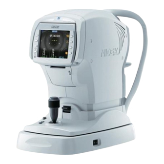
- Page 1 AUTO REFRACTOMETER, AUTO REF/KERATOMETER AR-310A/AR-330A/AR-360A ARK-510A/ARK-530A/ARK-560A SERVICE MANUAL September 2014 Pages in total: 218 XAR17ARDA001G/E...
-
Page 3: Table Of Contents
XAR17ARDA001G/E Table of Contents 1. INTRODUCTION ........9 2. - Page 4 XAR17ARDA001G/E 5 . 2 . 26 ERR043 (Printer connection error)......29 5 . 2 . 27 ERR101 (Sensor initialization error) .
- Page 5 XAR17ARDA001G/E 5 . 7 . 11 KM periphery cannot be measured ......58 5 . 7 . 12 CS measurement data is not normal .
- Page 6 XAR17ARDA001G/E 7 . 3 . 4 R/L motor (30602-EA26) ........84 7 .
- Page 7 Chart Adjustment ..........124 8 . 5 . 1 AR-310A, AR-330A, ARK-510A, ARK-530A ....124 8 . 5 . 2 AR-360A, ARK-560A .
- Page 8 AR-310A/AR-330A ........204...
-
Page 9: Introduction
For correct service, thorough understanding of the contents in this manual is required prior to the service. Refer to the Operator’s Manual and Parts List for the AR-310A, AR-330A, AR-360A, ARK-510A, ARK-530A, and ARK-560A. In case the device cannot be repaired according to the procedures described in this manual, please report the serial number of the device and details of the symptom or symptoms. - Page 10 XAR17ARDA001G/E This page is intentionally left blank. Return to previous page...
-
Page 11: Safety Precautions
XAR17ARDA001G/E 2 SAFETY PRECAUTIONS 1 . Requirements for prior contact regarding repair 1 ) When conducting repairs described in the Service Manual or Service Manual Annex, prior contact with NIDEK is not necessary. 2 ) When conducting repairs not covered in the Service Manual or Service Manual Annex, prior contact with the NIDEK Service Department in writing is required. - Page 12 XAR17ARDA001G/E 7 ) After loosening the screws fastened by a threadlocking adhesive, be sure to reapply the threadlocking adhesive to the screws before retightening them. 8 ) After replacing parts, confirm that they are fastened in their original positions securely before turning on the power.
-
Page 13: Specifications
3.1 Classifications 1 . Type of protection against electrical shock: Class I The AR-310A, AR-330A, AR-360A, ARK-510A, ARK-530A, and ARK-560A are classi- fied as Class I devices. A Class I device is one in which, in addition to basic insulation, protection against... -
Page 14: Specifications
XAR17ARDA001G/E 3.2 Specifications 1 . Objective measurement of refractive error (AR measurement) Spherical power (S) -30.00 to +25.00 D (VD = 12 mm) 0.01/0.12/0.25 D increments Cylindrical power (C) -12.00 to +12.00 D 0.01/0.12/0.25 D Cylinder axis (A) 0 to 180° 1°/5°... - Page 15 (entire) 9 . Working range of auto tracking Up and down ±16 mm or more Right and left ±5 mm (except AR-310A and ARK-510A) back and forth ±5 mm (except AR-310A and ARK-510A) 10. Movable range of horizontal direction Back and forth...
- Page 16 XAR17ARDA001G/E 12. Dimensions and mass Dimensions 260 mm (W) × 481 mm (D) × 455 mm (H) Mass 20 kg Power source AC 100 to 240 V ±10% 50/60 Hz Power consumption 100 VA 13. Environmental conditions (during use) Temperature 10 to 35ºC (50 to 95°F) Humidity 30 to 90ºC (No condensation)
-
Page 17: Troubleshooting
XAR17ARDA001G/E 4 TROUBLESHOOTING Connect the power cord, and turn on the power switch. Is the initial screen displayed? 5.1 Initial Screen is not Displayed (p19) Does an error message appear? 5.2 Error Message Appears (p22) Can the function buttons be operated? 5.3 Function Buttons are not Operational (p40) 5.4 Measuring Unit does not Move Smoothly along Does the main unit move horizontally? - Page 18 XAR17ARDA001G/E 5.8 Communication cannot be Performed Properly Can communication be performed properly? (p60) Can printing be performed? 5.9 Printing cannot be Performed (p60) 5.10 LCD Auto Sleep Function does not Operate Does the LCD auto sleep function operate? (p61) Turn off the power switch. Return to previous page...
-
Page 19: Subtroubleshooting
XAR17ARDA001G/E 5 SUBTROUBLESHOOTING 5.1 Initial Screen is not Displayed Is the power supply voltage proper? 5.1.1 Power supply voltage check (p20) Are the voltages between the following TPs on the tracking board (30601-BA02) as shown below (see [p185])? Replace the Tracking board (30601-BA02) (see TP6 and TP1: DC +3.3 V 7.2.2 [p74]). -
Page 20: Power Supply Voltage Check
XAR17ARDA001G/E 5.1.1 Power supply voltage check Is the power supply voltage proper? Set a voltage regulator. Is the voltage between the P001 1st and 3rd pins Replace the primary power supply unit (30601- on the primary power supply unit (30601-EA01) the EA01). -
Page 21: Backlight Of Color Lcd Does Not Light Up
XAR17ARDA001G/E 5.1.2 Backlight of color LCD does not light up Are the voltages between the P103 (J3) A27 and A28, and B27 and B28 pins on the main board Replace the Main board (see 7.2.1 [p73]). (30601-BA01) DC +12 V (see 9.3 [p185])? Are there any breaks in the BA01-BA03 cable... -
Page 22: Error Message Appears
XAR17ARDA001G/E 5.2 Error Message Appears 5.2.1 ERR001 (EEPROM error) Does an error appear in 17. EEPROM ERROR Perform adjustment and calibration according to DISP of MENU mode (see 8.1.1 [p103])? the error contents. Rewrite the EEPROM data of the driver board (30601-BA03) (see 8.15 [p173]). -
Page 23: Pd Error
XAR17ARDA001G/E 5.2.3 PD ERROR Is the PD phototransmitter soiled? Clean the PD phototransmitter. Does PD LED (30601-EA55) light up? 5.2.3.1 PD LED (30601-EA55) does not light up *Check it with a camera (a cellular phone camera (p23) or such). Are there any breaks in the PDC CD cable (30601- Replace the PDC CD cable (30601-EA30). -
Page 24: Err011 (Time-Out Error In Characters [Out])
XAR17ARDA001G/E 5.2.4 ERR011 (Time-out error in characters [OUT]) Correct the setting of the connected device. Is the setting of the connected device correct? (Refer to the operator's manual of the connected device.) Are there any breaks in the base cable (30601- Replace the base cable (30601-EA52). -
Page 25: Err012 (Time-Out Error For Receiving Data [Out])
XAR17ARDA001G/E 5.2.5 ERR012 (Time-out error for receiving data [OUT]) Perform the procedure as in “5.2.4 ERR011 (Time-out error in characters [OUT])” (p24). 5.2.6 ERR013 (Receiving error [OUT]) Perform the procedure as in “5.2.4 ERR011 (Time-out error in characters [OUT])” (p24). 5.2.7 ERR014 (Receiving code error [OUT]) Perform the procedure as in “5.2.4 ERR011 (Time-out error in characters [OUT])”... -
Page 26: Err026 (Dtr-Dsr Error [In])
XAR17ARDA001G/E 5.2.18 ERR026 (DTR-DSR error [IN]) Perform the procedure as in “5.2.4 ERR011 (Time-out error in characters [OUT])” (p24). 5.2.19 ERR027 (Data error [IN]) Perform the procedure as in “5.2.4 ERR011 (Time-out error in characters [OUT])” (p24). 5.2.20 ERR028 (Command error [IN]) Perform the procedure as in “5.2.4 ERR011 (Time-out error in characters [OUT])”... -
Page 27: Err032 (Left-To-Right Tracking Error)
XAR17ARDA001G/E 5.2.22 ERR032 (Left-to-right tracking error) Are there any breaks in the R/L motor (30602- Replace the R/L motor (30602-EA26) (see 7.3.4 EA26) (see 9.3 [p185])? [p84]). Are the voltages between the following pins of P209 (J9) on the tracking board (30601-BA02) as shown below when each sensor of the R/L sensor (30602-EA20) is shaded (see 9.3... -
Page 28: Err033 (Back-And-Forth Tracking Error)
XAR17ARDA001G/E 5.2.23 ERR033 (Back-and-forth tracking error) Are there any breaks in the F/B motor (30602- Replace the F/B motor (30602-EA27) (see 7.3.5 EA27) (see 9.3 [p185])? [p85]). Are the voltages between the following pins of P210 (J10) on the tracking board (30601-BA02) as shown below when each sensor of the F/B sensor (30602-EA21) is shaded (see 9.3... -
Page 29: Err043 (Printer Connection Error)
XAR17ARDA001G/E 5.2.26 ERR043 (Printer connection error) Is the cover closed? Close the cover. Open the cover once, then close it. Is the problem resolved? Is the voltage between the P316 (J16) 1st and 2nd pins on the driver board (30601-BA03) DC +5 V Replace the Driver board (30601-BA03) (see 7.2.3 (see 9.3 [p185])? -
Page 30: Err101 (Sensor Initialization Error)
XAR17ARDA001G/E Is the problem resolved? Replace the Driver board (30601-BA03) (see 7.2.3 [p75]). 5.2.27 ERR101 (Sensor initialization error) Are there any breaks in the wire (30601-M307)? Replace the Wire (30601-M307) (see 7.4.4 [p100]). Are there any breaks in the sensor motor (30601- Replace the Sensor motor (30601-E035) (see EA35) (see 9.3... -
Page 31: Err112 (Ar Motor Error)
XAR17ARDA001G/E 5.2.29 ERR112 (AR motor error) Are there any breaks in the prism motor cable Replace the prism motor cable (30601-EA34). (30601-EA34) (see 9.3 [p185])? Replace the Brushless motor (30601-E011) (see 7.3.18 [p94]).. Is the problem resolved? Replace the Driver board (30601-BA03) (see 7.2.3 [p75]). -
Page 32: Err123 (Chart Initialization Error)
XAR17ARDA001G/E 5.2.32 ERR123 (Chart initialization error) Are there any breaks in the chart (30703-EA74) Replace the Chart (30703-EA74) (see 7.3.15 (see 9.3 [p185])? [p92]). Replace the Driver board (30601-BA03) (see 7.2.3 [p75]). Is the problem resolved? Replace the Main board (see 7.2.1 [p73]). 5.2.33 ERR501 (Power error of Eye Care card) Replace the Eye Care card. -
Page 33: Err503 (Power Error Of Eye Care Card)
XAR17ARDA001G/E 5.2.35 ERR503 (Power error of Eye Care card) Perform the procedure as in “5.2.34 ERR502 (Writing error of Eye Care card)” (p32). 5.2.36 ERR601 (USB_A recognition error) Are there any USB devices other than the optional Remove the connected USB device (except the barcode scanner connected to the device?. -
Page 34: Err700 (File Sharing Error)
XAR17ARDA001G/E 5.2.38 ERR700 (File sharing error) Is the LAN cable connected to the LAN port? Connect the LAN cable. Is the network setting correct? Correct the network setting (see 8.16 [p174]). Contact the network administrator. 5.2.39 ERR703 (Hardware error) Turn off the power switch of the device, then turn it on again. -
Page 35: Err750 (Network Access Error)
XAR17ARDA001G/E 5.2.41 ERR750 (Network access error) Is the LAN cable connected to the LAN port? Connect the LAN cable. Is the network setting correct? Correct the network setting (see 8.16 [p174]). Are there any breaks in the LAN cable? Replace the LAN cable. Are there any breaks in the base cable (30601- Replace the base cable (30601-EA52). -
Page 36: Err751 (Network Writing Error)
XAR17ARDA001G/E 5.2.42 ERR751 (Network writing error) Is the folder in the destination PC set to the shared Set the folder in the destination PC to the shared folder? folder. Is the name of the folder in the destination PC the Correct the network setting (see 8.16 [p174]). -
Page 37: Err754 (Pc Name Error)
XAR17ARDA001G/E 5.2.43 ERR754 (PC name error) Is the LAN cable connected to the LAN port? Connect the LAN cable. Is the network setting correct? Correct the network setting (see 8.16 [p174]). Are there any breaks in the LAN cable? Replace the LAN cable. Is the destination PC connected by LAN? Connect the destination PC by LAN. -
Page 38: Err756 (Log-On Error)
XAR17ARDA001G/E 5.2.45 ERR756 (Log-on error) Is the user name entered in the user name field of Enter the correct user name in the user name field the network setting correct? of the network setting (see 8.16 [p174]). Is the password entered in the password field of the Enter the correct password in the password field of network setting correct? the network setting... -
Page 39: Err761 (Access Right Error)
XAR17ARDA001G/E 5.2.50 ERR761 (Access right error) Perform the procedure as in “5.2.45 ERR756 (Log-on error)” (p38). 5.2.51 ERR762 (Account error) Perform the procedure as in “5.2.45 ERR756 (Log-on error)” (p38). 5.2.52 ERR771 (Cable connection error) Is the LAN cable connected to the LAN port? Connect the LAN cable. -
Page 40: Function Buttons Are Not Operational
XAR17ARDA001G/E 5.3 Function Buttons are not Operational Are there conductions between the following pins of J1 on the left panel SW board (30601-BA07) when each switch on the panel is pressed (see 9.3 [p185])? Replace the Left panel SW board (30601-BA07) SW1: 3rd and 4th pins (see 7.2.6 [p77]). -
Page 41: Measuring Unit Does Not Move Smoothly Along Base Unit
XAR17ARDA001G/E 5.4 Measuring Unit does not Move Smoothly along Base Unit Clean the sliding plate (32105-M102). Is the problem resolved? Does the measuring unit move smoothly to the Replace the Sliding plate (32105-M102) (see 7.4.3 right, left, forward, and backward? [p99]). -
Page 42: Rotating Joystick Does Not Move Measuring Unit Up Or Down
XAR17ARDA001G/E 5.5 Rotating Joystick does not Move Measuring Unit Up or Down Are there any breaks in the U/D switch cable Replace the U/D switch cable (30601-EA25). (30601-EA25) (see 9.3 [p185])? Is the voltage between the P205 (J5) 8th and 9th Replace the Tracking board (30601-BA02) (see pins on the tracking board (30601-BA02) DC +5 V 7.2.2 [p74]). - Page 43 XAR17ARDA001G/E Replace the U/D motor (30601-EA28) (see 7.3.6 [p85]). Is the problem resolved? Replace the Main board (see 7.2.1 [p73]). Return to previous page...
-
Page 44: Chinrest Does Not Move Up Or Down
XAR17ARDA001G/E 5.6 Chinrest does not Move Up or Down Are there any breaks in the U/D switch cable Replace the U/D switch cable (30601-EA25). (30601-EA25) (see 9.3 [p185])? Are there conductions between the following pins of P205 (J5) on the tracking board (30601-BA02) when the up/down button is pressed (see 9.3 Replace the U/D SW board (30601-BA09) (see... - Page 45 XAR17ARDA001G/E Are the voltages between the following pins of P102 (J2) on the main board (30601-BA01) as shown below when each sensor of the chinrest (30601-EA53) is shaded (see 9.3 [p185])? Replace the Chinrest (30601-EA53) (see 7.3.12 • Up limit sensor: 4th and 7th pins When shaded: DC 0 V [p89]).
-
Page 46: Measurement Cannot Be Performed Properly
XAR17ARDA001G/E 5.7 Measurement cannot be Performed Properly Does an error appear? 5.2 Error Message Appears (p22) 5.7.1 Observed image is not displayed on LCD Is the observed image displayed on the LCD? (p48) Is the mire ring displayed? 5.7.2 Mire ring is not displayed (p49) Is the focus LED (30601-EA42) displayed? 5.7.3 Focus LED is not displayed (p49) Is the chart visible? - Page 47 XAR17ARDA001G/E Is the PD measurement data normal? 5.7.9 PD measurement data is not normal (p57) Is the KM measurement data normal? 5.7.10 KM measurement data is not normal (p58) Can the KM periphery be measured? 5.7.11 KM periphery cannot be measured (p58) Is the CS measurement data normal? 5.7.12 CS measurement data is not normal (p59) Is the PS measurement data normal?
-
Page 48: Observed Image Is Not Displayed On Lcd
XAR17ARDA001G/E 5.7.1 Observed image is not displayed on LCD Are the voltages between the following pins of P105 (J5) on the main board (30601-BA01) as shown below (see 9.3 [p185])? Replace the Main board (see 7.2.1 [p73]). 3rd and 2nd pins: DC +12 V 4th and 5th pins: DC +5 V Are there any breaks in the ARCCD2 cable (30601- Replace the ARCCD2 cable (30601-EA12). -
Page 49: Mire Ring Is Not Displayed
XAR17ARDA001G/E 5.7.2 Mire ring is not displayed Are the voltages between P309 (J9) 8th and 9th, Replace the Driver board (30601-BA03) (see 7.2.3 and 10th and 11th pins on the driver board (30601- [p75]). BA03) DC +15 V (see 9.3 [p185])? Are there any breaks in the mire cable (300601- Replace the mire cable (30601-EA39). -
Page 50: Chart Is Not Visible
XAR17ARDA001G/E 5.7.4 Chart is not visible Are there any breaks in the sensor carry cable Replace the sensor carry cable (30601-EA14). (30601-EA14) (see 9.3 [p185])? Are there any breaks in the chart LED (30601- Replace the Chart LED (30601-EA76) (see 7.3.14 EA76) (see 9.3 [p185])? -
Page 51: Alignment Is Not Automatically Performed By 3D Auto Tracking Function
XAR17ARDA001G/E 5.7.5 Alignment is not automatically performed by 3D auto tracking function 5.7.5.1 Alignment is not performed in side-to-side direction only * AR-330A, ARK-530A, AR-360A, and ARK-560A Does an error appear when the power is turned 5.2 Error Message Appears (p22) Is auto tracking icon 3D displayed? Display auto tracking icon 3D. -
Page 52: Alignment Is Not Performed In Up-And-Down Direction
XAR17ARDA001G/E 5.7.5.2 Alignment is not performed in up-and-down direction Does an error appear when the power is turned 5.2 Error Message Appears (p22) Is the auto tracking icon displayed? Display the auto tracking icon. Is the mire ring displayed? (Check it by using a 5.7.2 Mire ring is not displayed (p49) model eye.) Are there any breaks in the BA02-BA03 cable... -
Page 53: Alignment Is Not Performed In Forward-And-Backward Direction
XAR17ARDA001G/E 5.7.5.3 Alignment is not performed in forward-and-backward direction * AR-330A, ARK-530A, AR-360A, and ARK-560A only Does an error appear when the power is turned 5.2 Error Message Appears (p22) Is auto tracking icon 3D displayed? Display auto tracking icon 3D. Is the mire ring displayed? (Check it by using a 5.7.2 Mire ring is not displayed (p49) model eye.) -
Page 54: Measurement Does Not Start Even When Start Button Is Pressed
XAR17ARDA001G/E 5.7.6 Measurement does not start even when start button is pressed Activate manual mode. Is there conduction between the P902 1st and 2nd Replace the Joystick ASSY (30601-2600) (see pins on the joystick (30601-EA92) when the start 7.1.1 [p69]). button is pressed (see 9.3 [p185])? -
Page 55: Measurement Does Not Start Even When Alignment And Focus Are Achieved
XAR17ARDA001G/E 5.7.7 Measurement does not start even when alignment and focus are achieved Does an error appear? 5.2 Error Message Appears (p22) Display the auto shot icon. (Refer to the operator’s Is the auto shot icon displayed? manual.) Does the measurement start automatically? Replace the Driver board (30601-BA03) (see 7.2.3 [p75]). -
Page 56: Ar Measurement Data Is Not Normal
XAR17ARDA001G/E 5.7.8 AR measurement data is not normal Does BLK (blinking error) appear when a model 5.7.8.1 BLK (blinking error) (p57) eye is measured? Is the thumbnail result displayed properly on the Perform AR CALIBRATION (see 8.7 [p130]). LCD after the AR measurement? Are there any breaks in the ARCCD1 cable (30601- Replace the ARCCD1 cable (30601-EA72). -
Page 57: Blk (Blinking Error)
XAR17ARDA001G/E 5.7.8.1 BLK (blinking error) Is the result thumbnail displayed properly on the Perform AR CALIBRATION (see 8.7 [p130]). LCD after the measurement? Are there any breaks in the ARCCD1 cable (30601- Replace the ARCCD1 cable (30601-EA72). EA72) (see 9.3 [p185])? Are there any breaks in the sensor carry cable Replace the sensor carry cable (30601-EA14). -
Page 58: Km Measurement Data Is Not Normal
XAR17ARDA001G/E 5.7.10 KM measurement data is not normal Are there any breaks in the mire cable (30601- Do the mire ring and focus LED light up? EA39) (see 9.3 [p185])? Replace the Mire ASSY (30601-4000) Replace the mire cable (30601-EA39). (see 7.1.4 [p71]). -
Page 59: Cs Measurement Data Is Not Normal
XAR17ARDA001G/E 5.7.12 CS measurement data is not normal Perform the procedure as in “8.10 CS/PS Calibration” (p167). 5.7.13 PS measurement data is not normal Perform the procedure as in “8.10 CS/PS Calibration” (p167). Return to previous page... -
Page 60: Communication Cannot Be Performed Properly
XAR17ARDA001G/E 5.8 Communication cannot be Performed Properly Perform the procedure as in “5.2.4 ERR011 (Time-out error in characters [OUT])” (p24). 5.9 Printing cannot be Performed Does an error appear? 5.2 Error Message Appears (p22) Replace the printer cable (30601-EA32). Is the problem resolved? Adjust the printing density of the printer by parameter 34. -
Page 61: Lcd Auto Sleep Function Does Not Operate
XAR17ARDA001G/E 5.10 LCD Auto Sleep Function does not Operate Activate sleep mode. (Refer to the operator's Is sleep mode activated? manual.) Are there any breaks in the flexible flat cable Replace the flexible flat cable (30601-E021). (30601-E021) (see 9.3 [p185])? Are there any breaks in the flexible flat cable Replace the flexible flat cable (30601-E022). - Page 62 XAR17ARDA001G/E This page is intentionally left blank. Return to previous page...
-
Page 63: Removal Procedure
XAR17ARDA001G/E 6 REMOVAL PROCEDURE 6.1 Measuring Unit Left Cover (30601-M707) 1 . Remove the caps [32105-M730 (n = 4)]. 2 . Unscrew PC3 × 8 (n = 4). 3 . Remove the measuring unit left cover (30601-M707). 4 . Reassemble the parts in the reverse order. 6.2 Measuring Unit Right Cover (30601-M708) 1 . -
Page 64: Measuring Unit Front Cover Assy(30601-6300)
XAR17ARDA001G/E 6.3 Measuring Unit Front Cover ASSY(30601-6300) 1 . Remove the measuring unit left cover (30601-M707) (see 6.1 [p63]). 2 . Remove the measuring unit right cover (30601-M708) (see 6.2 [p63]). 3 . Remove the caps [32909-M541 (n = 4)]. 4 . -
Page 65: Measuring Unit Rear Cover Assy (30601-6000)
XAR17ARDA001G/E 6.5 Measuring Unit Rear Cover ASSY (30601-6000) 1 . Remove the measuring unit left cover (30601-M707) (see 6.1 [p63]). 2 . Remove the measuring unit right cover (30601-M708) (see 6.2 [p63]). 3 . Disconnect P311 (J11), P312 (J12), and P316 (J16) on the driver board (30601-BA03). 4 . -
Page 66: Bottom Plate (30601-M002)
XAR17ARDA001G/E 6.7 Bottom Plate (30601-M002) 1 . Unscrew BS3 × 6 (n = 4). 2 . Remove the bottom plate (30601-M002). 3 . Reassemble the parts in the reverse order. 6.8 Dust Cover (30601-M304) 1 . Remove the measuring unit rear cover ASSY (30601-6000) (see 6.5 [p65]). -
Page 67: Lcd Rear Cover (30601-M716)
XAR17ARDA001G/E 6.9 LCD Rear Cover (30601-M716) 1 . Unscrew PC3 × 5 (n = 4). 2 . Remove the LCD rear cover (30601- M716). 3 . Reassemble the parts in the reverse order. 6.10 LCD Front Cover (30601-M715) 1 . Remove the LCD ASSY (30601-6100) (see 7.1.5 [p71]). - Page 68 XAR17ARDA001G/E This page is intentionally left blank. Return to previous page...
-
Page 69: Replacement Procedure
XAR17ARDA001G/E 7 REPLACEMENT PROCEDURE 7.1 ASSYs 7.1.1 Joystick ASSY (30601-2600) Replacement part: 30601-2600 1 . Remove the rear body cover ASSY (30601-7000) (see 6.6 [p65]). 2 . Remove the GND cable of the joystick. 3 . Unscrew BS3 × 6 (n = 4) to replace the joystick ASSY (30601-2600). -
Page 70: Measuring Assy (30601-9E00)
XAR17ARDA001G/E 7.1.2 Measuring ASSY (30601-9E00) Replacement part: 30601-9E00 (except the AR-360A and ARK-560A) 1 . Remove the covers (see Section 6 [p63]). 2 . Remove the mire ASSY (see 7.1.4 [p71]). 3 . Disconnect P105 (J5) on the main board (30601-BA01) and P304 (J4), P305 (J5), P306 (J6), P315 (J15), and the ground wire on the driver board (30601-BA03). -
Page 71: Mire Assy (30601-4000)
XAR17ARDA001G/E 7.1.4 Mire ASSY (30601-4000) Replacement part: 30601-4000 1 . Remove the measuring unit front cover ASSY (30601-6300) (see 6.3 [p64]). 2 . Disconnect P401 (J1) on the mire board (30601-BA04). 3 . Unscrew BS3 × 8 (n = 4) to remove the mire ASSY (30601-4000). -
Page 72: Subjective Cylinder Assy (30703-3700)
XAR17ARDA001G/E 7.1.6 Subjective cylinder ASSY (30703-3700) Replacement part: 30703-3700 * Applies only to the AR-360A and ARK-560. 1 . Remove the covers (see Section 6 [p63]). 2 . Disconnect P307 (J7) and P308 (J8) on the driver board (30601-BA03). 3 . Unscrew BS3 × 8 (n = 2) to remove the subjective cylinder ASSY (30703-3700). -
Page 73: Boards
11 . After the replacement, turning on power to the device displays the following errors. 1 ) The AR-310A, AR-330A, AR-360A: ERR065 2 ) The ARK-510A, ARK-530A, ARK-560A: ERR066 * Do not turn off power to the device until the error is displayed. -
Page 74: Tracking Board (30601-Ba02)
XAR17ARDA001G/E 7.2.2 Tracking board (30601-BA02) Replacement part: 30601-BA02 1 . Remove the covers (see Section 6 [p63]). 2 . Disconnect all connectors on the tracking board (30601-BA02). 3 . Replace the tracking board (30601-BA02). 4 . Reassemble the parts in the reverse order. Return to previous page... -
Page 75: Driver Board (30601-Ba03)
PD CCD board 6 . After the replacement, turning on power to the device displays the following errors. 1 ) The AR-310A, AR-330A, AR-360A: ERR065 2 ) The ARK-510A, ARK-530A, ARK-560A: ERR066 * Do not turn off power to the device until the error is displayed. -
Page 76: Base Board (30601-Ba05)
XAR17ARDA001G/E 7.2.4 Base board (30601-BA05) Replacement part: 30601-BA05 1 . Remove the bottom plate (30601-M002) (see 6.7 [p66]). 2 . Disconnect all connectors on the base board (30601-BA05). 3 . Unscrew BS3 × 8 (n = 3) and TW3 (n = 2), and disconnect the connector cable (30601- EA01) and ground wire on the base board (30601-BA05). -
Page 77: Lcd Board (30601-Ba06)
XAR17ARDA001G/E 7.2.5 LCD board (30601-BA06) Replacement part: 30601-BA06 1 . Open the LCD ASSY (30601-6100) to remove the rear LCD cover (30601-M716) (see 6.9 [p67]). 2 . Disconnect all connectors on the LCD board (30601-BA06). 3 . Unscrew PC2 × 4 (n = 2). 4 . -
Page 78: U/D Sw Board (30601-Ba09)
XAR17ARDA001G/E 7.2.7 U/D SW board (30601-BA09) Replacement part: 30601-BA09 1 . Remove the rear body cover ASSY (30601-7000) (see 6.6 [p65]). 2 . Unscrew PT3 × 5 (n = 2). 3 . Replace the U/D SW board (30601-BA09). 4 . Reassemble the parts in the reverse order. 7.2.8 Sensor carry board (30601-BA14) Replacement part: 30601-BA14 1 . -
Page 79: Right Panel Sw Board (30601-Ba15)
XAR17ARDA001G/E 7.2.9 Right panel SW board (30601-BA15) Replacement part: 30601-BA15 1 . Remove the front LCD cover (30601-M715) (see 6.10 [p67]). 2 . Unscrew PT2 × 5 (n = 2) to replace the right panel SW board (30601-BA15). 3 . Reassemble the parts in the reverse order. Return to previous page... -
Page 80: Pd Boards
XAR17ARDA001G/E 7.2.10 PD boards 7.2.10.1 BA08 PD CCD board (32105-BA08) Replacement part: 32105-BA08 1 . Remove the measuring unit front cover ASSY (30601-6300) (see 6.3 [p64]). 2 . Disconnect all connectors on the BA08 PD CCD board (32105-BA08). 3 . Unscrew BS3 × 6 (n = 2) to replace the BA08 PD CCD board (32105-BA08). -
Page 81: Dc-Ac Inverter (18535-E010)
XAR17ARDA001G/E 7.2.11 DC-AC inverter (18535-E010) Replacement part: 18535-E010 1 . Open the LCD ASSY (30601-6100) to remove the rear LCD cover (30601-M716) (see 6.9 [p67]). 2 . Disconnect all connectors on the DC-AC inverter (18535-E010). 3 . Unscrew PC2 × 4 (n = 2) to replace the DC-AC inverter (18535-E010). -
Page 82: Electrical Components
XAR17ARDA001G/E 7.3 Electrical Components 7.3.1 R/L sensor (30602-EA20) Replacement part: 30602-EA20 * Applies only to the AR-330A, AR-360A, ARK-530A, and ARK-560. 1 . Remove the covers (see Section 6 [p63]). 2 . Unscrew BS3 × 6 to replace the R/L sen- sor (30602-EA20). -
Page 83: U/D Sensor (30601-Ea22)
XAR17ARDA001G/E 7.3.3 U/D sensor (30601-EA22) Replacement part: 30601-EA22 1 . Remove the covers (see Section 6 [p63]). 2 . Unscrew BS3 × 6 to replace the U/D sen- sor (30601-EA22). 3 . Reassemble the parts in the reverse order. Return to previous page... -
Page 84: R/L Motor (30602-Ea26)
XAR17ARDA001G/E 7.3.4 R/L motor (30602-EA26) Replacement part: 30602-EA26 * Applies only to the AR-330A, AR-360A, ARK-530A, and ARK-560A. 1 . Remove the covers (see Section 6 [p63]). 2 . Disconnect P102 (J2) on the main board (30601-BA01), and P201 (J1), P205 (J5), P208 (J8), P211 (J11), and the ground wire on the tracking board (30601-BA02). -
Page 85: F/B Motor (30602-Ea27)
XAR17ARDA001G/E 7.3.5 F/B motor (30602-EA27) Replacement part: 30602-EA27 * Applies only to the AR-330A, AR-360A, ARK-530A, and ARK-560A. 1 . Remove the covers (see Section 6 [p63]). 2 . Remove the measuring unit together with the tracking horizontal ASSY (30601-2500) (see 7.3.4 [p84]). -
Page 86: Origin Sensor (30601-Ea36)
XAR17ARDA001G/E 7.3.7 Origin sensor (30601-EA36) Replacement part: 30601-EA36 1 . Remove the covers (see Section 6 [p63]). 2 . Unscrew CK 2 × 4 (n = 2) to replace the origin sensor (30601-EA36). 3 . Reassemble the parts in the reverse order. 4 . -
Page 87: Cl Sensor (30703-Ea38)
XAR17ARDA001G/E 7.3.9 CL sensor (30703-EA38) Replacement part: 30703-EA38 * Applies only to the AR-360A and ARK-560A. 1 . Remove the subjective cylinder ASSY (30703-3700) (see 7.1.6 [p72]). 2 . Unscrew CK2 × 3 (n = 3) to remove the sensor retainer (30703-M395), then remove the infrared LED from the CL sen- sor (30703-EA38). -
Page 88: Focus Led(30601-Ea42)
XAR17ARDA001G/E 7.3.10 Focus LED(30601-EA42) Replacement part: 30601-EA42 1 . Remove the mire ASSY (30601-4000) (see 7.1.4 [p71]). 2 . Unscrew CK2 × 3 (n = 4) to replace the focus LEDs (30601-EA42 [n = 2]). 3 . Reassemble the parts in the reverse order. 4 . -
Page 89: Chinrest (30601-Ea53)
XAR17ARDA001G/E 7.3.12 Chinrest (30601-EA53) Replacement part: 30601-EA53 1 . Unscrew BS 3 × 6 (n = 2) to remove the lid (30601-M003). 2 . Disconnect P004 (J004). 3 . Unscrew SB3 × 10 to remove the chinrest ASSY (30601-5000). 4 . Unscrew SB3 × 10 (n = 3) to remove the chinrest cover (32105-M041). -
Page 90: Pd Led (30601-Ea55)
XAR17ARDA001G/E 7.3.13 PD LED (30601-EA55) Replacement part: 30601-EA55 1 . Remove the bottom plate (30601-M002) (see 6.7 [p66]). 2 . Disconnect P505 (J5) on the base board (30601-BA05). 3 . Unscrew BS3 × 6 to replace PD LED (30601-EA55). 4 . Reassemble the parts in the reverse order. 5 . -
Page 91: Chart Led (30601-Ea76)
EA76A) of the devices with serial numbers earlier than those shown in the following table is replaced with the new one (30601-EA76B). 1 ) Serial numbers of post-design change devices Countries other than Model China USA and China AR-310A 120001— 150621— 136114— AR-330A 220001— 250005—... -
Page 92: Chart (30703-Ea74)
XAR17ARDA001G/E 7.3.15 Chart (30703-EA74) Replacement part: 30703-EA74 * Applies only to the AR-360A and ARK-560A. 1 . Remove the chart disk ASSY (30703-3800) (see 7.1.7 [p72]). 2 . Unscrew CK2 × 4 (n = 2) to remove the disk cover (30703-M404). 3 . -
Page 93: B/W Ccd Camera (30601-E001)
XAR17ARDA001G/E 7.3.16 B/W CCD camera (30601-E001) 7.3.16.1 Measurement CCD camera Replacement part: 30601-E001 1 . Remove the covers (see Section 6 [p63]). 2 . Remove the cable clamp (80423-20153). 3 . Disconnect the connector on the B/W CCD camera (30601-E001). 4 . -
Page 94: Color Lcd (30601-E005)
XAR17ARDA001G/E 7.3.17 Color LCD (30601-E005) Replacement part: 30601-E005 1 . Remove the LCD front cover (30601-M715) (see 6.10 [p67]). 2 . Disconnect P001 (CN1) on the color LCD (30601-E005). 3 . Disconnect P002 (CN2) on the DC-AC inverter (18535-E010). 4 . Unscrew PC3 × 10 and N3, and disconnect the F.GND cable (30601-EA83). 5 . -
Page 95: Sensor Motor (30601-E035)
XAR17ARDA001G/E 7.3.19 Sensor motor (30601-E035) Replacement part: 30601-E035 1 . Remove the dust cover (30601-M304) (see 6.8 [p66]). 2 . Unscrew BS3 × 6 (n = 2) to remove the pulley 2 ASSY (30601-3120). 3 . Remove the wire (30601-M307) from the pulley (30601-M359) of the motor ASSY (30601-3600). -
Page 96: Switching Power Supply (80602-00102)
XAR17ARDA001G/E 8 . Attach the tension jig (30670-2100) to the measuring unit ASSY (30601-3000). 9 . Turn FC4 × 10 of the tension jig (30670- 2100) to adjust the tension of the wire (30601-M307) so that the focus base ASSY (30601-3300) moves smoothly. 10. -
Page 97: Printer (80606-00018)
XAR17ARDA001G/E 7.3.21 Printer (80606-00018) Replacement part: 80606-00018 1 . Remove the measuring unit rear cover (30601-6000) (see 6.5 [p65]). 2 . Unscrew PT3 × 8 (n = 2) to remove the printer cover (30601-M711). 3 . Remove the printer door cover (30601- M710). -
Page 98: Mechanical Components
XAR17ARDA001G/E 7.4 Mechanical Components 7.4.1 R/L shaft (30601-M201) Replacement part: 30601-M201 1 . Remove the covers (see Section 6 [p63]). 2 . Disconnect P201 (J1) on the tracking board (30601-BA02) and GND cable of the base cable (30601-EA52). 3 . Unscrew SB6 × 12 (n = 2) to remove the chin- rest ASSY (30601-5000) together with the base ASSY (30601-1000). -
Page 99: F/B Shaft (30601-M103)
XAR17ARDA001G/E 7.4.2 F/B shaft (30601-M103) Replacement part: 30601-M103 1 . Remove the R/L shaft (30601-M201) (see 7.4.1 [p98]). 2 . Unscrew HH5 × 6 (n = 4) to replace the F/ B shafts (30601-M103 [n = 2]). 3 . Reassemble the parts in the reverse order. * Reassemble the parts so that the side- to-side and forward-and-backward movements become smooth. -
Page 100: Wire (30601-M307)
XAR17ARDA001G/E 7.4.4 Wire (30601-M307) Replacement part: 30601-M307 1 . Remove the dust cover (30601-M304) (see 6.8 [p66]). 2 . Unscrew BS3 × 6 (n = 2) to remove the pulley 2 ASSY (30601-3120). 3 . Remove the wire (30601-M307) from the pulley (30601-M359) of the motor ASSY (30601-3600). -
Page 101: Linear Bearing
XAR17ARDA001G/E 7.4.5 Linear bearing 7.4.5.1 Linear bearing for F/B shafts (82001-LM028) Replacement part: 82001-LM028 1 . Unscrew HH5 × 6 (n = 4) to remove the F/B shafts (30601-M103 [n = 2]) and sliding plate (30601-M102) (see 7.4.2 [p99]). 2 . Unscrew TC3 × 5 (n = 4) to replace the linear bearings for F/B shafts (82001-LM028 [n = 4]). - Page 102 XAR17ARDA001G/E This page is intentionally left blank. Return to previous page...
-
Page 103: Adjustment
XAR17ARDA001G/E 8 ADJUSTMENT 8.1 Entering Adjustment Mode 8.1.1 MENU mode 1 . Turn on the power switch while pressing the L-1 and R-1 function buttons. * Continue pressing the function buttons until a beep sounds. 2 . The device starts, and the password entry screen appears. 3 . -
Page 104: Calib Mode Select (For Ar)
XAR17ARDA001G/E 8.1.2 CALIB MODE SELECT (for AR) 1 . Turn on the power switch while pressing the L-1 and R-2 function buttons. * Continue pressing the function but- tons until a beep sounds. 2 . The CALIB MODE SELECT screen is dis- played. -
Page 105: Parameter Settings
XAR17ARDA001G/E 8.1.5 Parameter settings 1 . Display the PARAMETER SETTING screen following the steps below. 1 ) For the AR-310A, AR-330A, and AR-360A * The icons on the AR-360A PARAMETER SETTING screen may be slightly differ- ent. a . Press the ring image enlarge-... -
Page 106: Calib Mode Select (For Km)
XAR17ARDA001G/E 2 . Press the up or down button to select the parameter to be changed, and press the execute button. * Parameters vary according to each model. 3 . Press the exit button to return to the measurement screen. 8.1.6 CALIB MODE SELECT (for KM) * The CALIB MODE SELECT screen for the KM can only be displayed in the ARK-510A, ARK-530A, and ARK-560A. -
Page 107: Jig Attachment Procedures
XAR17ARDA001G/E 8.2 Jig Attachment Procedures 8.2.1 Service optical adjustment jig (30670-5300) 1 . Remove the dust cover (30601-M304) (see 6.8 [p66]). 2 . Remove the mire ASSY (30601-4000) (see 7.1.4 [p71]). 3 . Connect the flexible flat cable (30601-E002) of the measuring unit rear cover ASSY (30601- 6000) to J4 on the relay board (30670-BA01). - Page 108 XAR17ARDA001G/E 6 . Connect the connector of the EA39 extension cable (32557-EA11) to J1 of the mire ASSY. 7 . Connect the connector of the EA39 extension cable (32557-EA11) to J9 on the driver board (30601-BA03). Return to previous page...
-
Page 109: Joint Jig (30670-1100)
XAR17ARDA001G/E 8.2.1.1 Joint jig (30670-1100) 1 . Attach the service optical adjustment jig (30670-5300) (see 8.2.1 [p107]). 2 . Attach the joint jig (30670-1100) to the measuring ASSY (30601-9E00) with FC3 × 15 (n = 2). 8.2.1.2 Reticle illumination jig (30670-1200) 1 . -
Page 110: 0-D Model Eye 2 (32177-0618)
XAR17ARDA001G/E 8.2.2 0-D model eye 2 (32177-0618) 1 . Attach the joint jig (30670-1100) to the measurement ASSY (30601-9E00) (see 8.2.1.1 [p109]). 2 . Attach 0-D model eye 2 (32177-0618) to the joint jig (30670-1100), and fasten it with the stepped knurled screw (82053- A308B). -
Page 111: Simple Calibration Model Eye (32107-6200)
XAR17ARDA001G/E 8.2.4 Simple calibration model eye (32107-6200) 1 . Attach the simple calibration model eye (32107-6200) with its notches aligned to the pins (34131-M112 [n = 2]) on the chin- rest ASSY (15601-1500). 8.2.5 Chinrest attachment jig (32107-1100) 1 . Attach the chinrest attachment jig (32107- 1100) to the chinrest ASSY (30601-5000). -
Page 112: 22-Model Eye Jig (32171-0600)
XAR17ARDA001G/E 8.2.6 22-model eye jig (32171-0600) 1 . Attach the chinrest attachment jig (32107-1100) (see 8.2.5 [p111]). 2 . Attach the 22-model eye jig (32171-0600) to the chinrest attachment jig (32107- 1100). * Fasten the jig with the fastening pin (32177-M513). -
Page 113: Chart Test Jig (32145-2100)
XAR17ARDA001G/E 8.2.8 Chart test jig (32145-2100) 1 . Attach the chinrest attachment jig (32107-1100) (see 8.2.5 [p111]). 2 . Attach the chart test jig (32145-2100) to the chinrest attachment jig (32107-1100). * Fasten the jig with the fastening pin (32177-M513). 3 . -
Page 114: Chart Test Jig (30670-2300)
XAR17ARDA001G/E 8.2.9 Chart test jig (30670-2300) 1 . Attach the chinrest attachment jig (32107-1100) (see 8.2.5 [p111]). 2 . Attach the chart test jig (30670-2300) to the chinrest attachment jig (32107-1100). * Fasten the jig with the fastening pin (32177-M513). 3 . -
Page 115: Dioptric Tester Jig (30670-6000)
4 . Disconnect P104 (J4) on the applicable main board below, then connect the con- nector of the diopter tester jig (30670- 6000) to P104 (J4) on the main board. 1 ) AR-310A: 30601-BA01P 2 ) AR-330A: 30602-BA01P 3 ) AR-360A: 30603-BA01P 4 ) ARK-510A: 30701-BA01P... -
Page 116: Km Calibration Jig (30670-0300)
XAR17ARDA001G/E 8.2.11 KM calibration jig (30670-0300) 1 . Attach the chinrest attachment jig (32107-1100) (see 8.2.5 [p111]). 2 . Attach the KM calibration jig (30670-0300) to the chinrest attachment jig (32107- 1100). * Fasten the jig with the fastening pin (32177-M513). -
Page 117: Ccd Camera Adjustment
Reticle 4 ) Use the steps below to remove the reticle illumination jig (30670-1200) from the devices with serial numbers earlier than those shown in the following table. Countries other than USA (S/N) (S/N) AR-310A 120001 134438 AR-330A 220001 230544... - Page 118 XAR17ARDA001G/E 5 ) Use the steps below to remove the reticle illumination jig (30670-1200) from the devices with serial numbers shown in the following table and later. Countries other than USA (S/N) (S/N) AR-310A 120001 134438 AR-330A 220001 230544 AR-360A...
- Page 119 XAR17ARDA001G/E 4 ) Adjust the SLD light using the stepped knurled screws (82053- A308B [n = 4]) on 0-D model eye 2 (32177-0618) so that the SLD light forms a circle. 5 ) Loosen SB3 × 6 (n = 2) to adjust the position of the camera ASSY (30601-3340) so that the SLD light is aligned to the centering box ( ...
- Page 120 XAR17ARDA001G/E 4 ) Loosen HH3 × 4 (n = 2) and adjust the inclination of the camera ASSY (30601-3340) so that the reticle hori- zontal line of the reticle illumination jig (30670-1200) becomes parallel to those on the screen. * Adjust the brightness of the hori- zontal lines on the screen with the up or down...
-
Page 121: Measurement Ccd Camera
XAR17ARDA001G/E 8.3.2 Measurement CCD camera 1 . Remove the dust cover (30601-M304) (see 6.8 [p66]). 2 . Remove the mire ASSY (30601-4000) (see 7.1.4 [p71]). 3 . Attach 0-D model eye 2 (32177-0618) (see 8.2.2 [p110]). 4 . Enter MENU mode, and select 5. AR CAMERA (see 8.1.1 [p103]). -
Page 122: Phototransmitter Adjustment
XAR17ARDA001G/E 8.4 Phototransmitter Adjustment 1 . When this task can be performed in a darkened room, perform the internal reflection removal (see 8.4.1 [p122]). 2 . If it is not possible, perform the AR SLD optical axis adjustment (see 8.4.2 [p123]). -
Page 123: Ar Sld Optical Axis Adjustment
XAR17ARDA001G/E 8.4.2 AR SLD optical axis adjustment 1 . Remove the dust cover (30601-M304) (see 6.8 [p66]). 2 . Remove the mire ASSY (30601-4000) (see 7.1.4 [p71]). 3 . Attach 0-D model eye 2 (32177-0618) (see 8.2.2 [p110]). 4 . Enter MENU mode, and select 5. AR CAMERA (see 8.1.1 [p103]). -
Page 124: Chart Adjustment
XAR17ARDA001G/E 8.5 Chart Adjustment 8.5.1 AR-310A, AR-330A, ARK-510A, ARK-530A * Applies only to the AR-310A, AR-330A, ARK-510A, and ARK-530A. * If the adjustment jigs are not available, return the device to the factory without perform- ing adjustment. 1 . Remove the dust cover (30601-M304) (see 6.8... -
Page 125: Ar-360A, Ark-560A
XAR17ARDA001G/E 8.5.2 AR-360A, ARK-560A 8.5.2.1 Subjective cylinder ASSY adjustment * The subjective cylinder ASSY must be adjusted for the emmetropic eyes. For astigmatic eyes, be sure to correct them before adjusting the subjective cylinder ASSY. 1 . Enter MENU mode, and select 2. CHART POSITION (see 8.1.1 [p103]). - Page 126 XAR17ARDA001G/E 5 . Press the function button to display CYL. * The chart changes to the clock dial chart. 6 . Move the subjective focus base ASSY Measuring (30703-3300) back and forth so that the window chart can be seen through the measuring window.
-
Page 127: Chart Position Adjustment
XAR17ARDA001G/E 8.5.2.2 Chart position adjustment * Applies only to the AR-360 and ARK-560A. * When adjustment jigs are not available, return the device to the factory without perform- ing adjustment. 1 . Remove the dust cover (30601-M304) (see 6.8 [p66]). 2 . - Page 128 XAR17ARDA001G/E b . Loosen HH3 × 4 to turn the chart lens 2 ASSY (30601- 3260). 9 . After the adjustment is complete, press the exit button and turn off power to the device. 10. Reassemble the removed units and covers. 11 .
-
Page 129: Alignment Calibration
XAR17ARDA001G/E 8.6 ALIGNMENT CALIBRATION 1 . Attach the 22-model eye jig (32171-0600) (see 8.2.6 [p112]). 2 . Enter MENU mode, and select 8. ALIGN- MENT CALIBRATION (see 8.1.1 [p103]). 3 . Perform alignment of the 0-D model eye as follows: 1 ) Align the mire ring that is slightly lit to the center of the target mark. -
Page 130: Ar Calibration
XAR17ARDA001G/E 8.7 AR CALIBRATION 8.7.1 AR CALIBRATION 1 . Attach the 22-model eye jig (see 8.2.6 [p112]). 2 . Display the CALIB MODE SELECT screen (for AR), and select AR (see 8.1.2 [p104]). 3 . Select CUSTOM with the up or down button, and press the execute button. - Page 131 8 . Press the auto button to select 3D auto tracking and auto shot * For the AR-310A and ARK-510A, the indication of auto tracking is * Icons vary depending on the model. 9 . Press the CYL mode button to select CYL-.
-
Page 132: Ar Axis
3D auto tracking and auto shot * For the AR-310A and ARK-510A, the indication of auto tracking is * Icons differ depending on the model. 11. Confirm that the measured value for each angle (0º, 45º, 90º, 135º) of the cylinder axis adjustment jig is within ±3°... -
Page 133: Axis Offset
XAR17ARDA001G/E 8.7.3 AXIS OFFSET 1 . Attach the cylinder axis adjustment jig (32177-1500) (see 8.2.7 [p112]). 2 . Display the CALIB MODE SELECT screen (for AR), and select AR CORRECT (see 8.1.2 [p104]). 3 . Select AXIS OFFSET with the up down button, then press the execute button. -
Page 134: Sph Offset
XAR17ARDA001G/E 8.7.4 SPH OFFSET * Change the SPH OFFSET values only when the AR measurement values differ by the same amount. 1 . Display the CALIB MODE SELECT screen (for AR), and select AR CORRECT (see 8.1.2 [p104]). 2 . Select SPH OFFSET with the up down button, then, press the execute button. -
Page 135: Chart Calibration
XAR17ARDA001G/E 8.7.5 CHART CALIBRATION 8.7.5.1 AR-310A/AR-330A/ARK-510A/ARK-530A 8.7.5.1.1 Chart test jig * If the adjustment jig is not available, return the device to the factory without performing adjustment. 1 . Attach the chart test jig (32145-2100 or 30670-2300) (see 8.2.8 [p113] and 8.2.9 [p114]). - Page 136 XAR17ARDA001G/E 3 ) Press the down button, and fol- low the steps below to adjust the - 12.00 D position. a . Turn the turret plate to select the -12.00 D lens (33510- G018). b . Press the left- button until the whole chart is focused for the first time.
- Page 137 XAR17ARDA001G/E 3 ) Press the down button, and follow the steps below to adjust the -12.00 D position. a . Turn the turret plate to select the -12.00 D lens (33510- G018). b . Press the left- or right+ button several times. c .
-
Page 138: Diopter Tester Jig Assy
XAR17ARDA001G/E 8.7.5.1.2 Diopter tester jig ASSY * If the adjustment jig is not available, return the device to the factory without performing adjustment. 1 . Attach the dioptric tester jig ASSY (30670-6000) (see 8.2.10 [p115]). 2 . Enter MENU mode, and select 10. CHART CALIBRATION (see 8.1.1 [p103]). - Page 139 XAR17ARDA001G/E 3 ) Press the down button, and follow the steps below to adjust the -12.00 D position. a . Turn the turret plate to select the -12.00 D lens (33510- G018). b . Press the left- button until the whole chart is focused for the first time.
- Page 140 XAR17ARDA001G/E 3 ) Press the down button, and follow the steps below to check the -12.00 D position. a . Turn the turret plate to select the -12.00 D lens (33510- G018). b . Press the left- or right+ button several times. c .
-
Page 141: Ar-360A/Ark-560A
XAR17ARDA001G/E 8.7.5.2 AR-360A/ARK-560A 8.7.5.2.1 Chart test jig * If the adjustment jig is not available, return the device to the factory without performing adjustment. 1 . Attach the chart test jig (30670-2300) (see 8.2.9 [p114]). 2 . Display the CALIB MODE SELECT screen (for AR), and select CHART (see 8.1.2 [p104]). - Page 142 XAR17ARDA001G/E 4 ) Press the down button, and fol- low the steps below to adjust the - 12.00 D position. a . Turn the turret plate to select the -12.00 D lens (33510- G018). b . Press the left- button until the whole clock dial chart is focused for the first time.
- Page 143 XAR17ARDA001G/E 5 . Perform THETA2 CALIB as follows: 1 ) Turn the turret plate to select the -5.36D CYL lens (33510-G044). 2 ) Press the page down button to select OFFSET. * The indication of “OS” turns red. 3 ) Perform adjustment with the left- or right+ button so that the whole clock dial chart can be seen in uni-...
- Page 144 XAR17ARDA001G/E 7 . Perform THETA2 CHECK as follows: 1 ) Turn the turret plate to select the -5.36D CYL lens (33510-G044). 2 ) Press the left- or right+ but- ton several times. 3 ) Perform adjustment with the left- or right+ button so that the clock dial chart can be seen in uniform clarity.
- Page 145 XAR17ARDA001G/E 11. Perform STAR CHECK as follows: 1 ) Select STAR CHECK with the up or down button, then press the execute button. 2 ) Follow the steps below to check the 0.00 D position. a . Turn the turret plate to select a position without any lens. b .
- Page 146 XAR17ARDA001G/E 13. Perform BALOON CALIB as follows: 1 ) Follow the steps below to adjust the 0.00 D position. a . Turn the turret plate to select a position without any lens. b . Press the left- button until the whole chart is focused for the first time.
- Page 147 XAR17ARDA001G/E 14. Perform BALOON CHECK as follows: 1 ) Follow the steps below to check the 0.00 D position. a . Turn the turret plate to select a position without any lens. b . Press the left- or right+ button several times. c .
-
Page 148: Dioptric Tester Jig Assy
XAR17ARDA001G/E 8.7.5.2.2 Dioptric tester jig ASSY * If the adjustment jig is not available, return the device without performing adjustment. 1 . Attach the dioptric tester jig ASSY (30670-6000) (see 8.2.10 [p115]). 2 . Display the CALIB MODE SELECT screen (for AR), and select CHART (see 8.1.2 [p104]). - Page 149 XAR17ARDA001G/E 5 ) Press the down button, and follow the steps below to adjust the -12.00 D position. a . Turn the turret plate to select the -12.00 D lens (33510-G018). b . Press the left- button until the whole clock dial chart is focused for the first time.
- Page 150 XAR17ARDA001G/E 5 . Perform THETA2 CALIB as follows: 1 ) Turn the turret plate to select the -5.36 D CYL lens (33510-G044). 2 ) Press the page down button to select OFFSET. * The indication of “OS” turns red. 3 ) Perform adjustment with the left- or right+ button so that the whole clock dial chart can be seen in...
- Page 151 XAR17ARDA001G/E 7 . Perform THETA2 CHECK as follows: 1 ) Turn the turret plate to select the -5.36 D CYL lens (33510-G044). 2 ) Press the left- or right+ but- ton several times. 3 ) Perform adjustment with the left- or right+ button so that the whole clock dial chart can be seen in...
- Page 152 XAR17ARDA001G/E 11. Perform STAR CHECK as follows: 1 ) Select STAR CHECK with the up or down button, then press the execute button. 2 ) Follow the steps below to check the 0.00 D position. a . Turn the turret plate to select a position without any lens. b .
- Page 153 XAR17ARDA001G/E 4 ) Follow the steps below to check the -12.00 D position. a . Turn the turret plate to select the -12.00 D lens (33510-G018). b . Press the left- or right+ button several times. c . Perform adjustment with the left- or right+ button so...
- Page 154 XAR17ARDA001G/E 3 ) Press the down button, and follow the steps below to adjust the -12.00 D position. a . Turn the turret plate to select the -12.00 D lens (33510-G018). b . Press the left- or right+ button several times. c .
- Page 155 XAR17ARDA001G/E 3 ) Press the down button, and follow the steps below to check the -12.00 D position. a . Turn the turret plate to select the -12.00 D (33510-G018) position. b . Press the left- or right+ button several times. c .
-
Page 156: Km Calibration
XAR17ARDA001G/E KM CALIBRATION * Applies only to the ARK-510A, ARK-530A, and ARK-560A. 8.8.1 KM CALIB 1 . Attach the KM calibration jig (30670-0300) (see 8.2.11 [p116]). 2 . Display the CALIB MODE SELECT screen (for KM), and select KM CALIB (see 8.1.6 [p106]). -
Page 157: Km Calib Check
XAR17ARDA001G/E 8.8.2 KM CALIB CHECK 8.8.2.1 ADJUST GAIN 1 . Attach the KM calibration jig (30670-0300) (see 8.2.11 [p116]). 2 . Display the CALIB MODE SELECT screen (for KM), and select KM ADJUST (see 8.1.6 [p106]). 3 . Select ADJUST GAIN with the up down button, then press the execute button. - Page 158 XAR17ARDA001G/E 7 . If the center measurement values are not within the specifications, perform correction as follows: * When the measurement values for each steel ball of the KM calibration jig (30670- 0300) differ by the same amount, change all correction factors by the same numeric value.
-
Page 159: Adjust Phi6 Gain
XAR17ARDA001G/E 8.8.2.2 ADJUST PHI6 GAIN 1 . Attach the KM calibration jig (30670-0300) (see 8.2.11 [p116]). 2 . Display the CALIB MODE SELECT screen (for KM), and select KM ADJUST (see 8.1.6 [p106]). 3 . Select ADJUST PHI6 AGAIN with the up or down button, then press the execute... - Page 160 XAR17ARDA001G/E 7 . If the peripheral measurement values are not within the specifications, perform correction as follows: * When the measurement values for each steel ball of the KM calibration jig (30670- 0300) differ by the same amount, change all correction factors by the same numeric value.
-
Page 161: Km Axis Check
XAR17ARDA001G/E 8.8.3 KM AXIS CHECK 1 . Attach the aspheric model eye (32177-1400) (see 8.2.12 [p116]). 2 . Display the CALIB MODE SELECT screen (for KM), and select KM AXIS CHECK (see 8.1.6 [p106]). 3 . Align the marking-off line to the three hori- zontal lines of the aspheric model eye. - Page 162 XAR17ARDA001G/E 8 . If the center KM measurement values are not within the specifications, perform the correc- tion as follows: 1 ) Press the reset button to select PHI3. 2 ) Change the numerical value with the and down buttons, * The measured values can be corrected within the range of ±5º.
-
Page 163: Pd Calibration
XAR17ARDA001G/E 8.9 PD CALIBRATION 8.9.1 CENTER POSITION 1 . Attach the PD checking jig (32545-1002) (see 8.2.13 [p116]). * A scale can be used as substitute for the PD checking jig (32545-1002). 2 . Enter MENU mode, and select 15. PD ADJUST MODE (see 8.1.1 [p103]). -
Page 164: Pd Calibration
XAR17ARDA001G/E 8.9.2 PD CALIBRATION 1 . Attach the PD checking jig (32545-1002) (see 8.2.13 [p116]). * A scale can be used as substitute for the PD checking jig (32545-1002). 2 . Enter MENU mode, and select 15. PD ADJUST MODE (see 8.1.1 [p103]). - Page 165 XAR17ARDA001G/E 7 . Align the focusing indicator to the 90 mm position of the jig, then press the start but- ton. 8 . Align the focusing indicator to the 10 mm position of the jig, then press the start but- ton.
- Page 166 XAR17ARDA001G/E 13. Measure the PD values at the 64 mm and 80 mm positions. Confirm that the mea- sured values are within the following spec- ifications. 1 ) PD 64 mm: less than 64 ±1.0 mm 2 ) PD 80 mm: within 80 ±1.0 mm 14.
-
Page 167: Cs/Ps Calibration
XAR17ARDA001G/E 8.10 CS/PS Calibration * Applies only to the ARK-510A, ARK-530A, and ARK-560A. 1 . Attach the PD checking jig (32545-1002) (see 8.2.13 [p116]). * A scale can be used as substitute for the PD checking jig (32545-1002). 2 . Enter MENU mode, and select 16. CS PS ADJUST (see 8.1.1 [p103]). -
Page 168: Auto Trc Adjust
XAR17ARDA001G/E 8.11 AUTO TRC ADJUST * Perform adjustment only when the R/L motor (30602-EA26), F/B motor (30602-EA27), or U/D motor (30601-EA28) is replaced. 1 . Attach the 22-model eye jig (32171-0600) (see 8.2.6 [p112]). 2 . Enter MENU mode, and select 11. TRC ADJUST MODE (see 8.1.1 [p103]) 3 . -
Page 169: Software Upgrade
XAR17ARDA001G/E 8.12 Software Upgrade 1 . Save the following upgrade files to the root of the USB flash drive. 1 ) For AR: ar17_softwrite_V***.mot 2 ) For ARK: ar17_softwrite_K***.mot * *** indicates the version number. * Do not create a folder to save the files in it. - Page 170 XAR17ARDA001G/E 9 . The screen as shown to the right appears and upgrade starts. 10. When the upgrade is complete, the screen as shown to the right appears. Turn off power to the device. 11. Disconnect the USB flash drive. 12.
-
Page 171: Time And Date Settings
XAR17ARDA001G/E 8.13 Time and Date Settings 1 . Display the PARAMETER SETTING screen, and select CLOCK SET (see 8.1.5 [p105]). 2 . Move the cursor to the item to be changed with the up or down button. 3 . Change the numeric value with the right or left button. -
Page 172: Cursor Board
XAR17ARDA001G/E 8.14 CURSOR BOARD 1 . Display the CALIB MODE SELECT screen (for AR), and select CURSOR BOARD (see 8.1.2 [p104]). 2 . Confirm that pink lines are displayed on all four edges of the color LCD (30601- E005). 3 . If they are not displayed, adjust the posi- tion of the LCD front cover (30601-M715) (see 6.10 [p67]). -
Page 173: Rewriting Eeprom Data
XAR17ARDA001G/E 8.15 Rewriting EEPROM Data * Rewrite the EEPROM data only when the driver board (30601-BA03) is replaced. * Improper operation may delete the adjustment data saved in the driver board (30601- BA03). 1 . Enter MENU mode, and select 17. EEPROM ERROR DISP (see 8.1.1 [p103]). -
Page 174: Setting Network
XAR17ARDA001G/E 8.16 Setting Network 1 . Display the PARAMETER SETTING screen, and select NETWORK (see 8.1.5 [p105]). 2 . Press the up or down button to select the desired item. 3 . Set the network. 1 ) Select 111. NETWORK. 2 ) Press the right or left button... - Page 175 XAR17ARDA001G/E 6 . Set the subnet mask. * When 112. DHCP is set to YES, 114. MASK indicates “0.0.0.0” and it cannot be selected. 1 ) Select 114. MASK. 2 ) Set the subnet mask in the same steps as those of the IP address. 7 .
- Page 176 XAR17ARDA001G/E 9 . Set the domain name. * Enter the domain name of the connected PC. 1 ) Select 117. DOMAIN. * Selecting 117. DOMAIN displays the execute button. 2 ) Set the domain name in the same steps as those of the user name. 10.
-
Page 177: Supplement
XAR17ARDA001G/E 9 SUPPLEMENT 9.1 Appearance 9.1.1 Front view Function buttons Memory indicator Cover open button Printer cover Start button Joystick Eye Care card slot Locking lever Power switch Return to previous page... -
Page 178: Rear View
XAR17ARDA001G/E 9.1.2 Rear view Forehead rest Eye level marker Measuring window Chinrest up/down button Chinrest PD window Return to previous page... -
Page 179: Labels
XAR17ARDA001G/E 9.2 Labels Front and side views Destination Label Marco label For countries other than –––––– –––––– USA, Canada, and China China –––––– Portuguese regions –––––– –––––– Canada –––––– Return to previous page... - Page 180 XAR17ARDA001G/E Rear view For technical assistance please call: Return to previous page...
- Page 181 XAR17ARDA001G/E Destination For countries other than USA, Canada, and China AR-310A 30601-M803-C AR-330A 30602-M803-C AR-360A –––––– label ARK-510A 30701-M803-C ARK-530A 30702-M803-C INPUT ARK-560A SER.NO. Multilingual label –––––– Return to previous page...
- Page 182 XAR17ARDA001G/E Destination For countries other than USA, Canada, and China Type B applied part label –––––– For technical assistance please call: MarcoFreeDial –––––– Chinese RoHS label 10 –––––– –––––– Return to previous page...
- Page 183 XAR17ARDA001G/E Destination Canada China AR-310A AR-330A AR-360A label ARK-510A ARK-530A INPUT ARK-560A SER.NO. Multilingual label –––––– –––––– Type B applied part label –––––– –––––– MarcoFreeDial –––––– –––––– Chinese RoHS label 10 –––––– Return to previous page...
- Page 184 XAR17ARDA001G/E Underside view For USA, Canada, and China For countries other than USA, Canada, and China Return to previous page...
-
Page 185: Wiring Diagram
XAR17ARDA001G/E 9.3 Wiring Diagram 9.3.1 Complete wiring diagram 9.3.1.1 30602-E000 (AR-330A and ARK-530A) Return to previous page... -
Page 186: 30601-E000 (Ar-310A And Ark-510A)
XAR17ARDA001G/E 9.3.1.2 30601-E000 (AR-310A and ARK-510A) Return to previous page... -
Page 187: 30603-E000 (Ar-360A) And 30703-E000 (Ark-560A)
XAR17ARDA001G/E 9.3.1.3 30603-E000 (AR-360A) and 30703-E000 (ARK-560A) Return to previous page... -
Page 188: Partial Writing Diagram
XAR17ARDA001G/E 9.3.2 Partial writing diagram 30601-EA01 30601-EA11 30601-EA12 Return to previous page... - Page 189 XAR17ARDA001G/E 30601-EA13 Cable 1: P301 A row side Cable 2: P301 B row side Return to previous page...
- Page 190 XAR17ARDA001G/E 30601-EA14 Return to previous page...
- Page 191 XAR17ARDA001G/E 30601-EA20 (AR-330A, AR-360A, ARK-530A, and ARK-560A only) 30601-EA21 (AR-330A, AR-360A, ARK-530A, and ARK-560A only) 30601-EA22 (AR-330A, AR-360A, ARK-530A, and ARK-560A only) Return to previous page...
- Page 192 XAR17ARDA001G/E 30601-EA23 30601-EA24 Return to previous page...
- Page 193 XAR17ARDA001G/E 30601-EA25 30601-EA26 (AR-330A, AR-360A, ARK-530A, and ARK-560A only) 30602-EA27 (AR-330A, AR-360A, ARK-530A, and ARK-560A only) 30601-EA28 Return to previous page...
- Page 194 XAR17ARDA001G/E 30601-EA30 30601-EA31 30601-EA32 Return to previous page...
- Page 195 XAR17ARDA001G/E 30601-EA34 30601-EA36 30601-EA39 30601-EA42 30601-EA44 Return to previous page...
- Page 196 XAR17ARDA001G/E 30601-EA51 30601-EA52 Return to previous page...
- Page 197 XAR17ARDA001G/E 30601-EA53 (Motor is included.) 30601-EA54 30601-EA55 Return to previous page...
- Page 198 XAR17ARDA001G/E 30601-EA63 30601-EA64 30601-EA65 30601-EA72 30601-EA75 Return to previous page...
- Page 199 XAR17ARDA001G/E 30601-EA76 30601-EA80 30601-EA81 30601-EA82 30601-EA83 Return to previous page...
- Page 200 XAR17ARDA001G/E 30601-EA93 type type 30703-EA37(AR-360A and ARK-560A only) (With motor) (With motor) Return to previous page...
- Page 201 XAR17ARDA001G/E 30703-EA38 (AR-360A and ARK-560A only) 30703-EA74 (AR-360A and ARK-560A only) (With motor) Return to previous page...
-
Page 202: Error Messages
XAR17ARDA001G/E 9.4 Error Messages Error codes Contents Details ERR001 EEPROM error Defective EEPROM data ERR002 Clock error Defective IC data of the clock PD ERROR PD error Defective PD CCD, LED does not light up. ERR011 Time-out error in characters (OUT) Communication breaks while receiving data. - Page 203 Reply error No reply received from PC *For the details of ERR061 to ERR068 caused by the combination of the main board and driver board, see the table below. Main board (30601-BA01) Unwritten AR-310A AR-330A AR-360A ARK-510A ARK-530A ARK-560A Unwritten...
-
Page 204: Parameter List
XAR17ARDA001G/E 9.5 Parameter List 9.5.1 AR-310A/AR-330A Countries other than Parameter item Item China USA and China STEP 0.25 D 0.25 D 0.25 D VERTEX D. 13.75 mm 12.00 mm 12.00 mm AXIS STEP 1° 1° 1° MEAS MODE Con. Con. - Page 205 XAR17ARDA001G/E Countries other than Parameter item Item China USA and China I/F MODE NIDEK NIDEK NIDEK I/F FORMAT SHORT SHORT SHORT BAUD-RATE 9600 9600 9600 COMMUNICATION BIT LENGTH CR CODE LM DATA PRINT READER START READER READER LENGTH NETWORK DHCP 192.168.0.20 192.168.0.20 192.168.0.20...
-
Page 206: Ar-360A
XAR17ARDA001G/E 9.5.2 AR-360A Countries other than Parameter item Item China USA and China STEP 0.25 D 0.25 D 0.25 D VERTEX D. 13.75 mm 12.00 mm 12.00 mm AXIS STEP 1° 1° 1° MEAS MODE Con. Con. Con. AI MODE AR CONTINUE AR THUMBNAIL PRINT... - Page 207 XAR17ARDA001G/E Countries other than Parameter item Item China USA and China AUTO SUBJECT SUBJECT CHART NEAR CHART 0.63 0.63 VA DISPLAY FRAC. SUBJECT SUBJECT START NEAR RECALL WD CHANGE UCVA CHART ADD SELECT 1.75 D 1.75 D 1.75 D READER START READER READER LENGTH NETWORK...
-
Page 208: Ark-510A/Ark-530A
XAR17ARDA001G/E 9.5.3 ARK-510A/ARK-530A Countries other than Parameter item Item China USA and China STEP 0.25 D 0.25 D 0.25 D VERTEX D. 13.75 mm 12.00 mm 12.00 mm AXIS STEP 1° 1° 1° MEAS MODE Con. Con. Con. AI MODE AR CONTINUE AR THUMBNAIL KM UNIT... - Page 209 XAR17ARDA001G/E Countries other than Parameter item Item China USA and China I/F MODE NIDEK NIDEK NIDEK I/F FORMAT SHORT SHORT SHORT BAUD-RATE 9600 9600 9600 COMMUNICATION BIT LENGTH CR CODE LM DATA PRINT SAGITTAL SAGITTAL SAGIT AXIS AXIS AXIS AXIS SAGIT PRINT READER START READER...
-
Page 210: Ark-560A
XAR17ARDA001G/E 9.5.4 ARK-560A Countries other than Parameter item Item China USA and China STEP 0.25 D 0.25 D 0.25 D VERTEX D. 13.75 mm 12.00 mm 12.00 mm AXIS STEP 1° 1° 1° MEAS MODE Con. Con. Con. AI MODE AR CONTINUE AR THUMBNAIL KM UNIT... - Page 211 XAR17ARDA001G/E Countries other than Parameter item Item China USA and China I/F MODE NIDEK NIDEK NIDEK I/F FORMAT SHORT SHORT SHORT BAUD-RATE 9600 9600 9600 COMMUNICATION BIT LENGTH CR CODE LM DATA PRINT SAGITTAL SAGITTAL SAGIT AXIS AXIS AXIS AXIS SAGIT PRINT AUTO SUBJECT SUBJECT CHART...
-
Page 212: Jig List
XAR17ARDA001G/E 9.6 Jig List Part No. Name Part No. Name Part No. Name High-power spherical 30670-0100 model eye 30670-0200 Small pupil model eye 30670-0300 KM calibration jig 30670-1100 Joint jig 30670-1200 Reticle illumination jig 30670-1300 Reticle observation jig 30670-1400 Camera jig 30670-1500 Ring lens illumination jig 30670-1600... -
Page 213: Adjustment Item List
XAR17ARDA001G/E 9.7 Adjustment Item List 9.7.1 ASSYs, boards, and adjustment items Replacement part 8.1.5 Parameter settings (p105) 8.3.1 Observation CCD camera (p117) 8.3.2 Measurement CCD camera (p121) 8.4 Phototransmitter Adjustment (p122) 8.5 Chart Adjustment (p124) 8.6 ALIGNMENT CALIBRATION (p129) 8.7 AR CALIBRATION (p130) 8.8 KM CALIBRATION (p156) 8.9 PD CALIBRATION (p163) 8.10 CS/PS Calibration (p167) -
Page 214: Electrical Components And Adjustment Items
XAR17ARDA001G/E 9.7.2 Electrical components and adjustment items Replacement part 8.3.1 Observation CCD camera (p117) 8.3.2 Measurement CCD camera (p121) 8.4 Phototransmitter Adjustment (p122) 8.5 Chart Adjustment (p124) 8.6 ALIGNMENT CALIBRATION (p129) 8.7 AR CALIBRATION (p130) 8.8 KM CALIBRATION (p156) 8.9 PD CALIBRATION (p163) 8.10 CS/PS Calibration (p167) 8.11 AUTO TRC ADJUST (p168) 8.13 Time and Date Settings (p171) -
Page 215: Mechanical Components And Adjustment Items
XAR17ARDA001G/E 9.7.3 Mechanical components and adjustment items Replacement part 8.3.1 Observation CCD camera (p117) 8.3.2 Measurement CCD camera (p121) 8.4 Phototransmitter Adjustment (p122) 8.5 Chart Adjustment (p124) 8.6 ALIGNMENT CALIBRATION (p129) 8.7 AR CALIBRATION (p130) 8.8 KM CALIBRATION (p156) 8.9 PD CALIBRATION (p163) 8.10 CS/PS Calibration (p167) 8.11 AUTO TRC ADJUST (p168) 8.13 Time and Date Settings (p171) -
Page 216: Screw List
XAR17ARDA001G/E 9.8 Screw List Return to previous page... - Page 218 NIDEK CO., LTD. : 34-14, Maehama, Hiroishi-cho, Gamagori, Aichi 443-0038, Japan (Manufacturer) Telephone: +81-533-67-6611 Facsimile: +81-533-67-6610 NIDEK CO., LTD : 3F Sumitomo Fudosan Hongo Bldg., 3-22-5, Hongo, (Tokyo Office) Bunkyo-Ku, Tokyo 113-0033, Japan Telephone: +81-3-5844-2641 Facsimile: +81-3-5844-2642 NIDEK INCORPORATED : 47651 Westinghouse Drive, Fremont, California 94539, U. S. A. (United States Agent) Telephone: +1-510-226-5700 Facsimile: +1-510-226-5750...
Need help?
Do you have a question about the AR-310A and is the answer not in the manual?
Questions and answers