Table of Contents
Advertisement
Quick Links
Advertisement
Table of Contents

Related Manuals for Nidek Medical HandyRef-K


Summary of Contents for Nidek Medical HandyRef-K
- Page 1 HANDHELD REF/KERATOMETER OPERATOR’S MANUAL...
- Page 2 Original instructions NIDEK CO., LTD. : 34-14 Maehama, Hiroishi-cho, Gamagori, Aichi 443-0038, JAPAN (Manufacturer) Telephone: +81-533-67-6611 URL: https://www.nidek.com/ NIDEK INC. : 2040 Corporate Court, San Jose, CA 95131, U.S.A. (United States Agent) Telephone: +1-800-223-9044 (USA Only) URL: https://usa.nidek.com/ NIDEK S.A. : Europarc, 13 rue Auguste Perret, 94042 Créteil, FRANCE (EU Authorized Representative) Telephone: +33 1 49 80 97 97...
- Page 3 Before Use This operator’s manual includes operating procedures, safety precautions, maintenance, and specifications for the NIDEK HANDHELD REF/KERATOMETER, HandyRef-K. The cautions for safety and operating procedures must be thor- oughly understood before using the device. Keep this manual handy for reference.
-
Page 4: Table Of Contents
Table of Contents SAFETY PRECAUTIONS - - - 1 1.1 For Safe Use - - - 1 1.2 Signal Words for Safety - - - 1 1.3 Usage Precautions - - - 2 1.4 Labels and Symbols - - - 9 INTRODUCTION - - - 11 2.1 Outline - - - 11 2.1.1 Device outline - - - 11... - Page 5 3.7.2 Cataract measurement mode - - - 63 3.7.3 Ring observation - - - 64 3.7.4 Retroillumination image observation - - - 65 3.7.5 Pupil size measurement (PS measurement mode) - - - 66 3.7.6 Contact lens measurement - - - 68 3.7.7 Sagittal measurement - - - 69 3.8 Printing Measured Values - - - 71 3.9 Measured Value List on Summary Screen - - - 76...
-
Page 7: Safety Precautions
SAFETY PRECAUTIONS For Safe Use BEFORE USE, READ THIS MANUAL. The cautions for safety and operating procedures must be thoroughly understood before using the device. The device complies with ISO 10342 subclause 4: 2010 (Ophthalmic instruments - Eye Refractometers) and ISO 10343 subclause 4: 2009 (Ophthalmic instruments - Ophthalmom- eters). -
Page 8: Usage Precautions
SAFETY PRECAUTIONS: Usage Precautions Usage Precautions Safety of LED CAUTION • The device is a Class 1 LED product. The LED used for the device is safe under expected use con- ditions including situations such as looking into the LED using an optical system. However, it is recommended to observe the following precautions when using the device: •... - Page 9 SAFETY PRECAUTIONS: Usage Precautions CAUTION • Do not use the device for any purposes other than the intended purpose. NIDEK is not responsible for accidents or malfunctions caused by misuse. For the intended purpose of the device, “2.1.2 Intended use” (page 11) •...
- Page 10 If the R/L indication is incorrect, press the R/L button to select the correct eye to be measured (R/L). • The measured values of objective refractive error obtained by the HandyRef-K are intended to be used as a reference for lens prescription for the correction of visual acuity with spectacles or contact lenses.
- Page 11 SAFETY PRECAUTIONS: Usage Precautions CAUTION • Never press on the LCD with a hard object such as a ball-point pen. • There may be a few defective or constantly-lit pixels on the LCD. This does not represent failure of the LCD; it is due to the structure of the LCD. •...
- Page 12 SAFETY PRECAUTIONS: Usage Precautions After use CAUTION • This device uses a heat-sensitive printer paper. The paper degrades over time and the printed char- acters may become illegible. If glue containing organic solvents or adhesives such as on adhesive tape comes in contact with the printer paper, the printed characters may become illegible. To keep the printed data for a long period of time, make copies of the printouts or write down the mea- sured results by hand.
- Page 13 SAFETY PRECAUTIONS: Usage Precautions Maintenance CAUTION • To ensure the continued safe use of the device, it is recommended that the manager of this device make sure that maintenance and preventive inspection are performed at least once a year. For details of maintenance and preventive inspection, ask NIDEK or your authorized distributor. If the manager of this device cannot perform the maintenance and preventive inspection, contact NIDEK or your authorized distributor.
- Page 14 SAFETY PRECAUTIONS: Usage Precautions Disposal CAUTION • Follow the local ordinances and recycling regulations regarding disposal or recycling of the device or its components, particularly when disposing of the battery pack (lithium ion battery), lithium battery used on the board, circuit board, plastic parts that contain brominated flame retardant, LCD, or power cord.
-
Page 15: Labels And Symbols
SAFETY PRECAUTIONS: Labels and Symbols Labels and Symbols To call attention to users, labels and indications are provided on the device. If labels are peeling off, characters are fading, or otherwise becoming illegible, contact NIDEK or your authorized distributor. •... - Page 16 SAFETY PRECAUTIONS: Labels and Symbols...
-
Page 17: Introduction
This device is a hand-held model that allows measurement of children who cannot hold their head on the stationary chinrest, bed-ridden patients or patients in an operating room. 2.1.2 Intended use The HANDHELD REF/KERATOMETER, HandyRef-K, is a medical device which measures objective refractive errors and corneal curvature radius of the patient’s eye. 2.1.3 Principles Objective refractive error measurement Fine measurement beams are projected on the fundus of the patient’s eye by a projecting optical... -
Page 18: Configuration
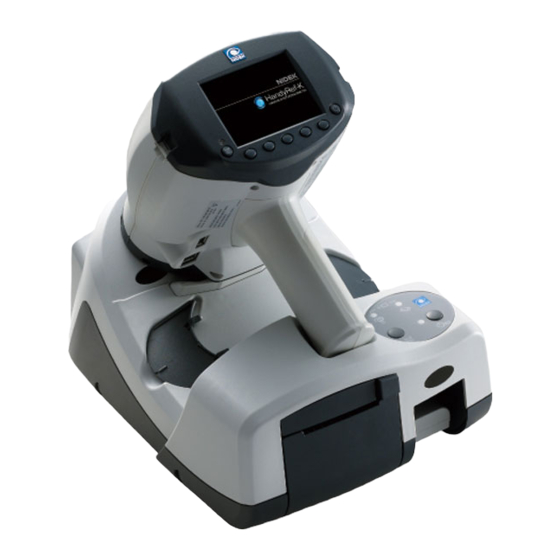
INTRODUCTION: Configuration Configuration ● Main body [Operator’s side] [Patient’s side] Displays the patient’s eye, target, focusing indicator, measurement values, number of measurement and such. Memory indicator Indicates that measured data is saved in memory. The indicator illuminates when data is being saved in memory. - Page 19 INTRODUCTION: Configuration Power button Turns on or off power to the device. Press to turn on the device. To turn off the device, hold down the button for more than a second. Neck strap attachment holes Attach the neck strap here. Holding the strap tight facilitates stable measurement.
- Page 20 INTRODUCTION: Configuration [Bottom view] Forehead rest Place against the patient’s forehead (above the eyebrows) to stabilize the main body. Press to release the forehead rest. Connection cable port The cable connecting the main body and station is connected here. When the cable is connected, the battery is not necessary for measurement. It also enables wired LAN communication and printing from the station.
- Page 21 INTRODUCTION: Configuration ● Station Spherical model eye Battery pack For the model without the printer: The printer, cable ports, and communication ports are not equipped. Only the charging function is available. Main body receptacle Place the main body here when not in use. When the main body is placed here, the battery pack inserted to the main body is automatically charged.
- Page 22 INTRODUCTION: Configuration Printer feed button Hold down this button to feed the printer paper. Pilot lamp Indicates that the station is turned on. When the power is supplied by the battery pack, the pilot lamp lights up when is pressed to turn on the power.
- Page 23 INTRODUCTION: Configuration [Rear view of the station] Power switch Turns on or off the AC power to the station. Power inlet The power cable is connected here. USB port The optional barcode scanner or magnetic card reader is connected here. Serial port (RS-232C) The refractor or EyeCa-RW2 is connected here for outputting data.
- Page 24 INTRODUCTION: Configuration ● Main screen • Descriptions in this operator’s manual are based on the WLAN-equipped model. Measurement mode Indicates the selected measurement mode (R and K: AR/KM mode, R: AR mode, K: KM mode). The number shown to the right is the number of measurements performed. The number in parenthe- ses shows the confidence index.
- Page 25 INTRODUCTION: Configuration Supine position mode icon This icon is displayed when the main body is tilted 60º or more downward so that the device enters supine position mode to measure a patient lying down. “3.6 Supine Position Mode (measurement for patients lying down)” (page 59) Patient number Indicates the examined patient’s number in 4-digit numerical order (after data is printed, performing the next measurement advances the number).
- Page 26 INTRODUCTION: Configuration Operation icons Operation icons are displayed here. Select the icon by pressing the corresponding function button under the icon. • In this operator’s manual, icon selection is presented as, for example, “Press ”. However, in actual operation, the function button under is pressed.
- Page 27 INTRODUCTION: Configuration Page 3 Operation icons Function Displays Page 1. [Page 3] Changes the direction in supine position mode. [Supine position] Displays the memory data screen. [Memory] Changes CYL mode. [CYL] Displays the parameter screen when held down for more than a second. [Parameter]...
- Page 28 INTRODUCTION: Configuration ● AR/KM measurement screen Target Used as a guide to locate the measuring optical axis in the center of the patient’s eye. Alignment guide mark Used as a guide to locate the target in the center of the cornea. Mire ring Used as an alignment reference ring.
- Page 29 INTRODUCTION: Configuration Inclination indicator Indicates the main body’s inclination level (ex. The value changes in 2º increments within the range from 0 to 12º, and in 3º increments within the range from 12 to 45º. The value indicates the main body’s inclination in horizontal direction as a reference. When the main body is tilted more than 45º, the number display changes to “--”.
-
Page 30: Packed Contents
INTRODUCTION: Packed Contents Packed Contents The following are included in the standard configuration. Check the contents before use. Part name Quantity Appearance Occluder 2 units Printer paper 3 rolls (printer-equipped model only) Battery pack 1 unit Connection cable (2 m) 1 unit Spherical model eye 1 unit... -
Page 31: Before First Use
INTRODUCTION: Before First Use Before First Use Perform the following operations before using the device for the first time: “2.4.1 Removing and installing the battery pack”, “2.4.2 Power cord connection”, “2.4.4 Attaching neck strap”, “2.4.5 Setting the printer paper”, “2.4.6 Other preparations” 2.4.1 Removing and installing the battery pack Perform the following to use the battery pack. -
Page 32: Power Cord Connection
INTRODUCTION: Before First Use 2.4.2 Power cord connection WARNING • Connect the power plug to a grounded outlet. Electric shock or fire may occur in the event of malfunction or power leakage. Place the station on a stable table. Connect the power cord to the power inlet. Power cord Confirm that the power switch is turned off and plug the power cord into the... -
Page 33: Charging The Battery Pack
INTRODUCTION: Before First Use 2.4.3 Charging the battery pack Charge the battery pack before use. The battery pack can be charged by either of the following methods: • Placing the main body on the station to charge (about 180 min.) •... - Page 34 INTRODUCTION: Before First Use Charging the battery pack inserted in the station Connect the power cord. Turn on the power switch of the station. With the terminals aligned as shown below, insert a battery pack into the battery slot. The station battery charge indicator lights up and charging starts. The charge indicator goes out when charging is complete.
-
Page 35: Attaching Neck Strap
INTRODUCTION: Before First Use 2.4.4 Attaching neck strap Attach the neck strap to the main body. The strap attachment holes are located on both sides of the LCD. Take out the strap, buckle, and holder Neck strap from the packet. Holder Buckle Pass the strap through the buckle and... - Page 36 INTRODUCTION: Before First Use Fold back the strap and pass it through the holder. Holder Pass the strap through the buckle. (Pass it from the inside). Take up any slack and check that there is Buckle no play in the strap. Attach the other end of the neck strap to the main body in the same manner.
-
Page 37: Setting The Printer Paper
INTRODUCTION: Before First Use 2.4.5 Setting the printer paper The setting and replacement procedures of the printer paper are described here. CAUTION • Be sure to use only the printer paper (80620-00001) specified by NIDEK. If printer paper other than that specified is used, the printer head may be damaged due to printing failure or paper jam, or printed contents may easily become illegible. - Page 38 INTRODUCTION: Before First Use Replacing the printer paper When a red line appears along the edge of the printer paper, it means that the paper is running short. In such a case, replace the printer paper with a new roll. Press to open the printer cover, then remove any remaining printer paper.
-
Page 39: Other Preparations
INTRODUCTION: Before First Use 2.4.6 Other preparations Set the printer paper. “2.4.5 Setting the printer paper” (page 31) • If no printer paper is loaded, the error message “OUT OF PAPER” appears when is pressed. (This message does not appear while the device is communicating by infrared.) As necessary, insert a charged battery pack into the main body. -
Page 40: Startup Of Main Body
INTRODUCTION: Before First Use 2.4.7 Startup of main body Press to turn on the main body. Confirm that the screen is displayed. In a few seconds, the initial screen appears. Initializa- tion starts and the memory indicator blinks. When initialization completes, the memory indicator goes out and the screen changes to the main screen. -
Page 41: Powering The Station By Battery Pack
INTRODUCTION: Before First Use 2.4.8 Powering the station by battery pack Normally, the station operates by an AC power supply. However, the station can be powered by the battery pack by the following procedure. This is a supplemental function. In principle, it is recommended to connect the station to an AC power supply. -
Page 42: Connecting The Main Body And Station
INTRODUCTION: Connecting the Main Body and Station Connecting the Main Body and Station There are three methods to connect the main body and the station. Connection by cable • Connection by infrared (wireless) • Connection by wireless LAN • 2.5.1 Connection by cable CAUTION... -
Page 43: Connection By Infrared (Printer-Equipped Model Only)
INTRODUCTION: Connecting the Main Body and Station To remove the cable, hold down the clasp of the plug, then pull it out. Clasp 2.5.2 Connection by infrared (printer-equipped model only) The main body and station communicate by infrared light. Communication is possible both when the main body is placed on the station or separated from the station. -
Page 44: Connection By Wireless Lan (Printer-Equipped Model Only)
INTRODUCTION: Connecting the Main Body and Station Communication with the main body separated from the station Separate the main body from the station, then aim the IR windows of the main body toward the IR receptor B of the station for communication. Set the “... -
Page 45: Functionality Depending On Communication Method
INTRODUCTION: Connecting the Main Body and Station 2.5.4 Functionality depending on communication method Availability of the printing and external communication methods differs depending on the type of con- nection between the main body and the station set by the “ 91. STATION I/F” (page 98) parameter. The following table shows the availability of communication methods. - Page 46 INTRODUCTION: Connecting the Main Body and Station...
-
Page 47: Operating Procedure
OPERATING PROCEDURE Operation Flow “3.3 Startup and Shutdown” “3.3.1 Device startup” (page 43) “3.3.2 Device shutdown” (page 47) “3.4 Operating Procedure and Measurement Method” (page 48) “3.5 AR (refractive error) and KM (corneal curvature radius) Measurements” (page 54) “3.5.1 AR/KM measurement mode” (page 54) “3.5.2 AR measurement mode”... -
Page 48: Screen List
OPERATING PROCEDURE: Screen List Screen List Parameter Settings Ring image display Retroillumination image observation Main screen Parameter Start Measurement completion AR/KM Pupil size measurement Memory data measurement All screens are accessible from either the main screen or AR/ Printing Sagittal measurement KM measurement screen. -
Page 49: Startup And Shutdown
OPERATING PROCEDURE: Startup and Shutdown Startup and Shutdown 3.3.1 Device startup Press to turn on the main body. The main screen appears. When the “ 71. WINDOW CHECK” (page 96) parameter is set to “YES” or “DAY”, the measur- ing window is checked for cleanliness. Press on the handle. - Page 50 OPERATING PROCEDURE: Startup and Shutdown Checklist before use Checklist before use - HandyRef-K Item Date and personnel The power cord is securely connected to the power inlet and power outlet. The cables of the connected devices are securely con- nected.
- Page 51 OPERATING PROCEDURE: Startup and Shutdown Operation of the measuring window check function When the “ 71. WINDOW CHECK” (page 96) parameter is set to “YES” or “DAY”, the measuring win- dow is checked for cleanliness at device startup. An unclean measuring window has considerable influence on the measured results. In addition to visual inspection, this checking function should be used to ensure measurement with a clean measur- ing window.
- Page 52 OPERATING PROCEDURE: Startup and Shutdown • When “WINDOW CHECK NG” is displayed: Turn off the device, then check that the measuring window is clean. If not, clean it. • The measuring window is checked for cleanliness before the first measurement every time the device is turned on.
-
Page 53: Device Shutdown
OPERATING PROCEDURE: Startup and Shutdown 3.3.2 Device shutdown To finish measurement, hold down of the main body for more than a second to turn it off. Turn off the power switch of the station. When the station is powered by the battery pack, hold down for more than a second to turn it off. -
Page 54: Operating Procedure And Measurement Method
OPERATING PROCEDURE: Operating Procedure and Measurement Method Operating Procedure and Measurement Method This section describes the operating procedures and measure- ments common to all measurement modes. Put the neck strap around the operator’s neck. Holding the strap tight facilitates stable measurement. The strap also prevents the device from falling. CAUTION •... - Page 55 OPERATING PROCEDURE: Operating Procedure and Measurement Method If necessary, read the patient ID using the optional barcode scanner or magnetic card reader. “3.11.3 Handling of barcode scanner and magnetic card reader” (page 86) Set the main body for measurement. Forehead rest Press the forehead rest to release it.
- Page 56 OPERATING PROCEDURE: Operating Procedure and Measurement Method Hold the main body level. ● When the “ 7. AXIS CORRECTION” parameter is set to “NO”: When the “ 7. AXIS CORRECTION” (page 90) parameter is set to “NO”, the inclination of the main body is displayed by the inclination indica- tor under the mire ring.
- Page 57 OPERATING PROCEDURE: Operating Procedure and Measurement Method Bring the main body close to the patient and lightly place the forehead rest against their forehead (just above the eyebrow of the eye being measured). Adjust the main body position so that the eye level marker on the main body or occluder is aligned with the patient's eye.
- Page 58 OPERATING PROCEDURE: Operating Procedure and Measurement Method Adjust the main body position so that the align- ment guide mark on the patient’s eye comes within the target “ ”. Alignment guide Target mark Bring the patient’s eye into focus. When the target “ ”...
- Page 59 OPERATING PROCEDURE: Operating Procedure and Measurement Method Optimum condition Indicator bar Reduce the number of bars Green arrow Minimum pupil diameter mark When the main body is too close to the patient’s eye • When the main body is too close to the patient’s eye, the red focusing indicator is displayed. Move the main body in the direction of the red arrow (backward) so that the number of the indica- tor bars is reduced.
-
Page 60: Ar (Refractive Error) And Km (Corneal Curvature Radius) Measurements
OPERATING PROCEDURE: AR (refractive error) and KM (corneal curvature radius) Measurements AR (refractive error) and KM (corneal curvature radius) Mea- surements This section describes the AR (refractive error) and KM (corneal curvature radius) measurements. The measurement mode is selectable among R/K (AR/KM measurement mode), R (AR measurement mode), and K (KM measurement mode). - Page 61 OPERATING PROCEDURE: AR (refractive error) and KM (corneal curvature radius) Measurements Number of AR measurements and KM measurements • The number of AR measurements differs depending on the “ 5. AM MODE” (page 89) parameter setting. When the number of measurements specified by the “ 6.
- Page 62 OPERATING PROCEDURE: AR (refractive error) and KM (corneal curvature radius) Measurements • When the specified number of KM measurements is not obtained, is displayed on the screen. Pressing performs KM measurement. When the specified number of measurements is obtained, is displayed on the screen. •...
-
Page 63: Ar Measurement Mode
OPERATING PROCEDURE: AR (refractive error) and KM (corneal curvature radius) Measurements 3.5.2 AR measurement mode AR (refractive error) measurement is performed. Perform Steps 1 to 11 of “3.4 Operating Procedure and Measurement Method” (page 48). Press in Step 3 to select R (AR measurement mode). In Step 11, when the focus is aligned to the eye, AR measurement starts automatically. -
Page 64: Km Measurement Mode
OPERATING PROCEDURE: AR (refractive error) and KM (corneal curvature radius) Measurements 3.5.3 KM measurement mode KM (corneal curvature radius) measurement is performed. Perform Steps 1 to 11 of “3.4 Operating Procedure and Measurement Method” (page 48). Press in Step 3 to select K (KM measurement mode). In Step 11, when the focus is aligned to the eye, KM measurement starts automatically. -
Page 65: Supine Position Mode (Measurement For Patients Lying Down)
OPERATING PROCEDURE: Supine Position Mode (measurement for patients lying down) Supine Position Mode (measurement for patients lying down) The following explains supine position mode when measurement is taken from the patient’s side. During this measurement, the cylinder axis is compensated by 90 degrees. •... - Page 66 OPERATING PROCEDURE: Supine Position Mode (measurement for patients lying down) As necessary, change the measurement direction. Press on the supine position mode screen to display page Press to select the measurement direction. Pressing switches the measurement direc- tion (side ↔ above). Icon Measurement direction Measurement position...
- Page 67 OPERATING PROCEDURE: Supine Position Mode (measurement for patients lying down) Press to select the eye to be measured. In supine position mode, the eye to be measured (R/L) is not automatically detected. The right eye is selected as default. As necessary, press to select the correct eye to be mea- sured ( Right eye: Select...
-
Page 68: Other Measurements
OPERATING PROCEDURE: Other Measurements Other Measurements This section describes the following measurement modes: “3.7.1 Quick measurement mode”, “3.7.2 Cataract measurement mode”, “3.7.3 Ring observation”, “3.7.4 Retroillumination image observation”, “3.7.5 Pupil size measurement (PS measurement mode)”, “3.7.6 Contact lens measurement” 3.7.1 Quick measurement mode For measurement of children or patients who cannot fixate their eyes, the auto shot function does not work... -
Page 69: Cataract Measurement Mode
OPERATING PROCEDURE: Other Measurements 3.7.2 Cataract measurement mode When measurement is not possible due to cataract or abnormal eyes during AR (refractive error) measurement, the device enters cataract measurement mode automatically. Perform normal measurement. When the device is placed in cataract measurement mode, is displayed on the screen and then measurement starts. -
Page 70: Ring Observation
OPERATING PROCEDURE: Other Measurements 3.7.3 Ring observation The ring image obtained during measurement is displayed on the screen. It allows the condition of the patient’s eye to be observed. Perform AR measurement. “3.5.1 AR/KM measurement mode” (page 54) Display the ring image screen. Press to display page Press... -
Page 71: Retroillumination Image Observation
OPERATING PROCEDURE: Other Measurements 3.7.4 Retroillumination image observation This procedure checks for opacity around a crystalline lens. • Keep the main body as stable as possible when capturing retroillumination images. • When the “ 31. PRINT” (page 92) parameter is set to “AUTO”, to print the retroillumination image together with AR and KM measurement values, capture retroillumination images before the AR and KM measurements. -
Page 72: Pupil Size Measurement (Ps Measurement Mode)
OPERATING PROCEDURE: Other Measurements 3.7.5 Pupil size measurement (PS measurement mode) This section describes operation procedure for manual PS measurement when the “ 75. AUTO PS” (page 96) parameter is set to “ ”. When this parameter is set to , the following procedure is not necessary. - Page 73 OPERATING PROCEDURE: Other Measurements Change the eye to be measured (R/L). Measure the other eye in the same manner. Switching the eye to be measured opens the screen displayed in Step 2. • When the “ 31. PRINT” (page 92) parameter is set to “AUTO”, to print pupil size (PS) measurement values together with AR and KM measurement values, perform pupil size (PS) measurement before the AR and KM measurements.
-
Page 74: Contact Lens Measurement
OPERATING PROCEDURE: Other Measurements 3.7.6 Contact lens measurement To measure the curvature of hard contact lenses, use the provided contact lens holder. Fill the concave top of the contact lens holder with water. Use a commercial pipette to fill the concave top of the CL holder completely with water. -
Page 75: Sagittal Measurement
OPERATING PROCEDURE: Other Measurements 3.7.7 Sagittal measurement The corneal peripheral positions are measured to calculate the eccentricity (values that indicate the characteristic of the conic section). • Keep the main body as stable as possible when performing sagittal measurement. Set the “ 21. SAGITTAL”... - Page 76 OPERATING PROCEDURE: Other Measurements The measured eccentricity value is dis- played on the main screen. Measured values other than eccentricity value are printed or output to a computer. Sample printout The following are sample printouts for the left eye and explanations of each data item. ●...
-
Page 77: Printing Measured Values
OPERATING PROCEDURE: Printing Measured Values Printing Measured Values Three printing settings (“PRINT1” to “PRINT3”) are available to customize the printing contents. Set the parameters as necessary or desired. “● PRINT1 (Print setting 1)” (page 92), “● PRINT2 (Print setting 2)” (page 93), “● PRINT3 (Print setting 3)”... - Page 78 OPERATING PROCEDURE: Printing Measured Values Check the printed measurement results. The results are printed from the station’s printer. At the same time, the data is saved to the main • body. When the “ 32. OUTPUT W/PRINT” (page 92) parameter is set to “YES”, the data is output to •...
- Page 79 OPERATING PROCEDURE: Printing Measured Values ● Sample printout <Sample printout - 2> <Sample printout - 1> Items added to the standard printing Standard printing by default...
- Page 80 OPERATING PROCEDURE: Printing Measured Values ● Print contents Description Patient number Patient ID Patient ID scanned by the optional barcode scan- ner or magnetic card reader Name and sex Measurement date and time Vertex distance The distance between the corneal vertex to the posterior surface of spectacle lenses Corneal refractive index Printed when KM measurement is performed with...
- Page 81 OPERATING PROCEDURE: Printing Measured Values Description Trial lens data These are the values that were converted auto- matically from the cylinder values so that the sphere values for the trial lens become smaller based on the AR median values (the latest val- ues when median values have not been obtained).
-
Page 82: Measured Value List On Summary Screen
OPERATING PROCEDURE: Measured Value List on Summary Screen Measured Value List on Summary Screen Various measured values (median values or the latest values when median values have not been obtained) can be displayed together on the summary screen. Measured values can be checked, printed, or output from this screen. -
Page 83: Memory Data Management
OPERATING PROCEDURE: Memory Data Management 3.10 Memory Data Management 3.10.1 Saving memory data The latest measurement data of up to 50 patients (100 eyes) can be saved in the main body memory. The data is automatically saved when it is printed. When the “... -
Page 84: Printing All Saved Data
OPERATING PROCEDURE: Memory Data Management 3.10.2 Printing all saved data All measured data saved in the main body is printed. By the “ 33. MEMORY PRINT” (page 92) parameter, printing only (PRINT), data output only (OUT- PUT), or both (BOTH) can be selected. When “PRINT”... -
Page 85: Printing Selected Data
OPERATING PROCEDURE: Memory Data Management During printing, the message “NOW PRINTING… □/□” is displayed. Pressing the STOP button cancels the printing from the next data. When printing is complete, the message “NOW PRINTING… □/□” disappears. • The printing contents differ depending on the parameters. •... - Page 86 OPERATING PROCEDURE: Memory Data Management Select or deselect data. Select the data to be selected or deselected by pressing Press to select or deselect the data by line. Pressing selects or deselects the data by page. Press The message “PRINT SELECTED DATA” appears. Print the selected data.
-
Page 87: Deleting Memory Data
OPERATING PROCEDURE: Memory Data Management 3.10.4 Deleting memory data All measured data saved in the main body is deleted. Display the MEMORY DATA MANAGE- MENT screen. Press to display page Press to display the MEMORY DATA MANAGEMENT screen. Select “ALL CLEAR” with button and press message... -
Page 88: Connection And Handling Of Peripheral Devices
OPERATING PROCEDURE: Connection and Handling of Peripheral Devices 3.11 Connection and Handling of Peripheral Devices The device can export data to an external device such as the NIDEK motorized refractor or a com- puter. The patient ID can be imported using the optional barcode scanner or magnetic card reader. ... - Page 89 OPERATING PROCEDURE: Connection and Handling of Peripheral Devices CAUTION • Do not use devices other than the specified barcode scanner or magnetic card reader. IDs cannot be read correctly or device malfunction may result. • Be sure to perform LAN connection via a network switch. Data communication may not be properly performed.
-
Page 90: Connection With Computer
OPERATING PROCEDURE: Connection and Handling of Peripheral Devices 3.11.2 Connection with computer The following three types of connection are available for outputting data to a connected computer. Connection by LAN cable (by station) • Connection by wireless LAN • Export by a USB flash drive •... - Page 91 OPERATING PROCEDURE: Connection and Handling of Peripheral Devices Export to a USB flash drive Export the data to a USB flash drive inserted in the main body, then insert this USB flash drive to the computer to transfer data. ● Connection procedure Insert the USB flash drive (specified by NIDEK) to the USB port at the bottom of the main body.
-
Page 92: Handling Of Barcode Scanner And Magnetic Card Reader
OPERATING PROCEDURE: Connection and Handling of Peripheral Devices 3.11.3 Handling of barcode scanner and magnetic card reader • Although a patient ID can be read before or after measurement, read it before printing the measured results. • If a patient ID is read with the measured data that has been printed still displayed, the device recog- nizes the displayed data as that of a former patient, and erases it automatically. -
Page 93: Parameter Settings And Maintenance
PARAMETER SETTINGS AND MAIN- TENANCE Parameter Settings 4.1.1 Setting procedure Various device parameter settings can be changed from the PARAMETER SETTING screen. Before changing or implementing the “● COMMUNICATION (communication function)” (page 97), “● NETWORK 1 (LAN communication function 1)” (page 99), and “● NETWORK 2 (LAN communication function 2)”... - Page 94 PARAMETER SETTINGS AND MAINTENANCE: Parameter Settings Press to select the parameter option to be changed. Press to change the setting. For details of the parameter options, “4.1.2 Parameter settings” (page 89) Hold down for more than a second. The parameter setting is saved and the screen returns to the previous screen.
-
Page 95: Parameter Settings
PARAMETER SETTINGS AND MAINTENANCE: Parameter Settings 4.1.2 Parameter settings • Underlined options indicate factory settings. ● AR (AR measurement) AR parameter screen Parameter option Setting contents 1. AR STEP 0.12D / 0.25D (Refractive power measure- Selects the display increments of SPH or CYL for refractive power measurement. ment increments) 0.00mm / 10.50mm / 12.00mm / 13.75mm / 15.00mm / 16.50mm Selects the distance between the corneal vertex to the spectacle lens when... - Page 96 PARAMETER SETTINGS AND MAINTENANCE: Parameter Settings YES / NO 7. AXIS CORRECTION Sets whether to detect the main body’s inclination by the sensor to perform (Axis compensation) automatic axis correction using the level position (0º) as the reference. The axis correction function is disabled in supine position mode. NORMAL / QUICK 8.
- Page 97 PARAMETER SETTINGS AND MAINTENANCE: Parameter Settings ● SAGITTAL SAGITTAL parameter screen Parameter option Setting contents YES / NO 21. SAGITTAL Sets whether to conduct sagittal measurement after KM measurement. (Sagittal measurement) When “YES” is selected, the SAG icon is displayed on the AR/KM measure- ment screen.
- Page 98 PARAMETER SETTINGS AND MAINTENANCE: Parameter Settings ● PRINT1 (Print setting 1) PRINT1 parameter screen Parameter option Setting contents MANUAL / AUTO / NO Sets the printing operation from among MANUAL, AUTO, and NO. • MANUAL: Pressing the print button starts printing. 31.
- Page 99 PARAMETER SETTINGS AND MAINTENANCE: Parameter Settings LOW / MEDIUM / HIGH 36. PRINT DENSITY (Density of printed text) Sets the density of the printed text from among LOW, MEDIUM, and HIGH. YES / NO 37. PATIENT NO. (Printing of patient number) Sets whether to print the patient number.
- Page 100 PARAMETER SETTINGS AND MAINTENANCE: Parameter Settings YES / NO Sets whether to display and print erroneous data of AR measurement. When set to “YES” and the measured results are erroneous, the measured 54. ERROR DATA values are displayed in yellow on the screen. (Erroneous data) In addition, the printed measured data is preceded by “Err”.
- Page 101 PARAMETER SETTINGS AND MAINTENANCE: Parameter Settings YES / NO 63. TL PRINT Sets whether to print trial lens data based on the AR median values (or the (Printing of trial lens data) latest values when the median values have not been obtained). YES / NO 64.
- Page 102 PARAMETER SETTINGS AND MAINTENANCE: Parameter Settings ● FUNCTION (Various functions) FUNCTION parameter screen Parameter option Setting contents YES / DAY / NO Sets whether to automatically check the measuring window for cleanliness. The measuring window is automatically checked for cleanliness before 71.
- Page 103 PARAMETER SETTINGS AND MAINTENANCE: Parameter Settings ● READER (Barcode scanner / magnetic card reader function) • When data is received from the barcode scanner or magnetic card reader, the results under the set reading start position and reading length are displayed in the frame. •...
- Page 104 PARAMETER SETTINGS AND MAINTENANCE: Parameter Settings Parameter option Setting contents CABLE / WLAN / IR / NO Sets the communication method between the main body and station • CABLE: A connection cable is used for communication. • WLAN: Wireless LAN is used for communication. •...
- Page 105 PARAMETER SETTINGS AND MAINTENANCE: Parameter Settings ● NETWORK 1 (LAN communication function 1) NETWORK 1 parameter screen Parameter option Setting contents YES / NO Sets whether to turn on DHCP connection. 101. DHCP When the DHCP server is provided, IP is automatically assigned. (DHCP connection) * When the “...
- Page 106 PARAMETER SETTINGS AND MAINTENANCE: Parameter Settings AD HOC / INFRA. Sets the operation mode for wireless LAN. Select from ad hoc mode (AD HOC) or infrastructure mode (INFRA.). * “AD HOC” cannot be selected when WPA or WPA2 is used as the wireless encryption method.
- Page 107 PARAMETER SETTINGS AND MAINTENANCE: Parameter Settings Parameter option Setting contents NIDEK / NIDEK+ACK Sets the network connection (LAN/WLAN) to the computer. • NIDEK: Data is output in a specification specified by NIDEK. 111. NETWORK • NIDEK+ACK: (Network connection) The following error processing is added to “NIDEK”. After the receiver receives data, the file is deleted or renamed.
-
Page 108: Checking The Mac Address
PARAMETER SETTINGS AND MAINTENANCE: Parameter Settings 4.1.3 Checking the MAC address MAC address of the device can be checked when it is needed for the network connection setting. On the PARAMETER SETTING screen, select “MAC ADDRESS” with button and press The MAC ADDRESS screen appears (it may take a few seconds before the screen appears). -
Page 109: Setting Station Parameters
PARAMETER SETTINGS AND MAINTENANCE: Parameter Settings 4.1.4 Setting station parameters ● When setting station parameters On the PARAMETER SETTING screen, select “SET STATION” with button and press The station parameter settings set by the main body are applied to the station. While the settings are being applied, the message “SETTING OF STATION”... -
Page 110: Setting The Date And Time
PARAMETER SETTINGS AND MAINTENANCE: Parameter Settings 4.1.5 Setting the date and time Set the date and time for the printout. On the PARAMETER SETTING screen, select “SET CLOCK” with button and press The SET CLOCK screen is displayed. Set the date and time in the SET CLOCK screen. -
Page 111: Entering Comments
PARAMETER SETTINGS AND MAINTENANCE: Parameter Settings 4.1.6 Entering comments Printed comments can be changed (the default setting is “NIDEK HandyRef-K”). On the PARAMETER SETTING screen, select “SET COMMENT” with button and press The SET COMMENT screen is displayed. Enter desired comments on the SET COM- MENT screen. -
Page 112: Maintenance
PARAMETER SETTINGS AND MAINTENANCE: Maintenance Maintenance 4.2.1 Troubleshooting Should the device function improperly, attempt to correct the problem according to the following table before contacting NIDEK or your authorized distributor. When Remedy • Check whether the battery pack is inserted properly. ... -
Page 113: Error Messages And Remedies
PARAMETER SETTINGS AND MAINTENANCE: Maintenance 4.2.2 Error messages and remedies If one of the following error codes is displayed on the screen or printed out, follow the suggestions in the cause and remedy column. Notify NIDEK of the error code, message number, and serial number of your device so that NIDEK can offer appropriate service. - Page 114 PARAMETER SETTINGS AND MAINTENANCE: Maintenance ● Network communication Error message Cause and remedy ERROR 700 • Error related to Windows file sharing CIFS ERR ERROR 900 CIFS ERR (WLAN) ERROR 902 • Check the power supply, SSID name, security, and password of the access point.
-
Page 115: Measurement Accuracy Check
PARAMETER SETTINGS AND MAINTENANCE: Maintenance Error message Cause and remedy ERROR 772 • Acknowledgment error The file is deleted within 5 seconds or not renamed. NO NETWORK ACK ERROR 972 • Check whether the capture software on the computer is properly activated. NO NETWORK ACK (WLAN) ∗... - Page 116 PARAMETER SETTINGS AND MAINTENANCE: Maintenance Perform AR and KM measurements in the same manner as normal AR and KM mea- surements to check the results. If the measured results differ substantially from the values indicated on the spherical model eye, con- tact NIDEK or your authorized distributor.
-
Page 117: Cleaning
PARAMETER SETTINGS AND MAINTENANCE: Maintenance 4.2.4 Cleaning Cleaning the device When the cover or panel of the device becomes dirty, clean it with a soft cloth. For severe stains, soak the cloth in a neutral detergent or rubbing alcohol, wring well, and wipe. Finally dry with a soft, dry cloth. -
Page 118: Consumable List
PARAMETER SETTINGS AND MAINTENANCE: Maintenance Check if the window is cleaned using a penlight. If soiled areas remain, clean the window again with new cleaning paper. • When the “ 71. WINDOW CHECK” (page 96) parameter is set to “YES” or “DAY”, the measuring window is checked for cleanliness at device start-up. -
Page 119: Specifications And Technical Information
SPECIFICATIONS AND TECHNICAL INFORMATION Specifications Main body • Objective refractive Sphere -20.00 to +20.00 D (VD = 12 mm) (0.12 / 0.25 D increments) error measurement Cylinder 0 to ±12.00 D (0.12 / 0.25 D increments) Axis 0 to 180° (1°/ 5° increments) Minimum measur- 2 mm in diameter able pupil diameter... - Page 120 SPECIFICATIONS AND TECHNICAL INFORMATION: Specifications • Power specification Battery pack Lithium-ion battery (7.2 V 1800 mAh) Station feed DC 9 V 2 A (maximum) • Dimensions and mass Dimensions 206 (W) × 181 (D) × 224 (H) mm (including occluders) Mass 998 g (including battery pack) Station...
- Page 121 SPECIFICATIONS AND TECHNICAL INFORMATION: Specifications Environment and others • Environmental condi- Temperature 10 to 35°C (50 to 95°F) tions Humidity 30 to 90% (non-condensing) (during use) Atmospheric pres- 800 to 1,060 hPa sure Installation location Indoors Others A well ventilated location that is not exposed to extraneous light (direct sunlight) or water, and free from hazardous parti- cles, vibration, bumping, smoke, or fumes •...
-
Page 122: Glossary And Abbreviations
SPECIFICATIONS AND TECHNICAL INFORMATION: Glossary and Abbreviations Glossary and Abbreviations The following terms and abbreviations are used in the device and operator's manual. Glossary and Abbreviations Term Details For AR measurement, measurement automatically finishes after the specified AM mode number of measurements if the data is stable without variations. If unstable data is included, two additional measurements are taken and then measurement finishes. -
Page 123: Emc (Electromagnetic Compatibility)
SPECIFICATIONS AND TECHNICAL INFORMATION: EMC (Electromagnetic Compatibility) EMC (Electromagnetic Compatibility) The device is suitable for use in stores and hospitals except for near active HF surgical equipment and RF shielded rooms with an ME system for magnetic resonance imaging, where the intensity of electro- magnetic disturbances is high. - Page 124 SPECIFICATIONS AND TECHNICAL INFORMATION: EMC (Electromagnetic Compatibility) Specified cable Connector Part name Cable shielded Ferrite core Length (m) shielded Power cord Connection cable LAN cable Communication cable 15.0 USB cable Specified multimedia equipment Network switch: Complied with CISPR 32 Class B •...
- Page 125 SPECIFICATIONS AND TECHNICAL INFORMATION: EMC (Electromagnetic Compatibility) Guidance and manufacturer’s declaration - electromagnetic emissions The device is intended for use in the electromagnetic environment specified below. The customer or the user of the device should assure that it is used in such an environment. Emissions test Compliance Electromagnetic environment - guidance...
- Page 126 SPECIFICATIONS AND TECHNICAL INFORMATION: EMC (Electromagnetic Compatibility) Guidance and manufacturer's declaration - electromagnetic immunity The device is intended for use in the electromagnetic environment specified below. The customer or the user of the device should assure that it is used in such an environment. Immunity test IEC 60601 test level Compliance level...
- Page 127 SPECIFICATIONS AND TECHNICAL INFORMATION: EMC (Electromagnetic Compatibility) ● Precaution by FCC This device incorporates a wireless communication module for the specified shipping destinations. When using this device in the USA, follow the cautions below provided by the FCC. Precaution common to the main body and station: •...
- Page 128 SPECIFICATIONS AND TECHNICAL INFORMATION: EMC (Electromagnetic Compatibility)
- Page 129 are reserved by NIDEK or the owner of the Third-Party- IMPORTANT—READ CAREFULLY Software. The license granted herein will not be intended as, or construed to be, any assignment of the rights of THIS AGREEMENT APPLIES TO THE NIDEK SOFT- NIDEK or the owner of the Third-Party-Software. The WARE AND ACCOMPANYING DOCUMENTS.
- Page 130 Agreement with immediate effect. Upon termination of provisions of this Agreement will continue in full force this Agreement due to the breach of this Agreement, and effect. NIDEK reserves all the rights to claim damages resulting 11. SURVIVAL from such breach. 11.1.The provisions of 2, 3, 4, 6, 7, 8, 9, 10, 12, 13, 14, 15, 6.2.
Need help?
Do you have a question about the HandyRef-K and is the answer not in the manual?
Questions and answers