
Related Manuals for Nidek Medical GYC-1000


Summary of Contents for Nidek Medical GYC-1000
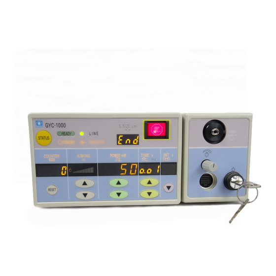
- Page 1 NIDEK GREEN LASER PHOTOCOAGULATOR Model GYC-1000 COMBINATION DELIVERY UNIT [ATTACHABLE TO NIDEK YC-1300/1400, YC-1600] OPERATOR’S MANUAL (SUPPLEMENT TO THE GYC-1000 OPERATOR’S MANUAL)
- Page 2 * Specifications are subject to change without notice for improvement. NIDEK CO., LTD. : 34-14, Maehama, Hiroishi-cho, Gamagori, Aichi 443-0038, Japan (Manufacturer) Telephone: (0533) 67-6611 Facsimile: (0533) 67-6610 NIDEK CO., LTD : 6th Floor, Takahashi Bldg., No.2, 3-chome, Kanda-jinboucho (Tokyo Office) Chiyoda-ku, Tokyo 101-0051, Japan Telephone: (03) 3288-0571 Facsimile: (03) 3288-0570...
- Page 3 When the exposure time or the interval time (in the repeat mode) on the display of the control box of the GYC-1000 is less than “1.00” or “1.0”, “0” before the decimal point is displayed small. (Example: if the setting is “0.30”, the display shows “...
-
Page 4: Table Of Contents
Table of Contents § 1 Page INTRODUCTION ....................... 1-1 1.1 Outline of the Combination Delivery Unit ..............1-1 1.2 Classifications of the Combination Delivery Unit ............1-2 1.3 Symbol Information ....................1-3 § 2 SAFETY ......................... 2-1 2.1 Storage, Transport, and Installation Precautions ............2-1 2.2 Wiring and Connection Precautions ................ - Page 5 § 6 MAINTENANCE ......................6-1 6.1 Cleaning ........................6-1 6.1.1 Cleaning the exterior ..................6-1 6.1.2 Cleaning the optical parts ................... 6-1 § 7 SPECIFICATIONS ...................... 7-1 § 8 ACCESSORIES......................8-1 8.1 Standard Configurations ................... 8-1 8.2 Options ........................8-1 Words in This Manual..................End of this manual...
-
Page 6: Introduction
YAG laser beam while performing the observation with the slit lamp of the YAG laser system. This delivery unit is mounted on the slit lamp of the YAG laser system and connected to the NIDEK GREEN LASER PHOTOCOAGULATOR, Model GYC-1000 using the connecting cable and fiber-optic cable. -
Page 7: Classifications Of The Combination Delivery Unit
1 - 2 1.2 Classifications of the Combination Delivery Unit [Classification under the provision of 93/42/EEC (MDD)] Class IIb As long as this delivery unit is connected to the main body, this delivery unit is classified as a Class IIb unit. [Class of the laser system] Class 4 As long as this delivery unit is connected to the main body, this unit is classified into Class 4 system. -
Page 8: Symbol Information
1 - 3 [Mode of operation] As long as this delivery unit is connected to the main body, this unit is an continuous operating system. [Classification by transportability] This delivery unit is classified as a transportable system. 1.3 Symbol Information This symbol means that the system is classified as a system with a type B applied part. -
Page 9: Safety
SAFETY § 2 In this manual, signal words are used to designate the degree or level of safety alerting. The definitions are as follows. WARNING: Indicates a potentially hazardous situation which, if not avoided, could result in death or serious injury. CAUTION: Indicates a potentially hazardous situation which, if not avoided, may result in minor or moderate injury or in a property damage... -
Page 10: Wiring And Connection Precautions
2 - 2 CAUTION • In installation of the combination system, observe the following instructions: - To avoid troubles from condensation, let the combination system sit until the condensation has dissipated before installation. - To avoid malfunction from change in temperature and condensation, do not install the combination system where it is exposed to the direct flow of air conditioning. -
Page 11: Usage Precautions
2 - 3 2.3 Usage Precautions WARNING • Use of controls or adjustments, or performance of procedures other than those specified herein may result in hazardous radiation exposure. • In handling of the delivery unit, observe the following instructions: - Only service technicians properly trained by Nidek may install and configure the combination system. - Page 12 • For laser emission, observe the following instructions: - When the green laser beam (wavelength: 532 nm) of the GYC-1000 is emitted into tissue, following symptoms may occur. Pay attention to the direction of the aiming beam to avoid emitting the laser beam into the eye or onto skin inadvertently.
-
Page 13: After Use Precaution, Maintenance, And Checks
2 - 5 2.4 After Use Precaution, Maintenance, and Checks CAUTION • After use of the combination system, observe the following instructions: - To avoid the tracking phenomenon, if the system will not be used for a long period of time, disconnect the power cord from the grounded power outlet. -
Page 14: Disposal
2 - 6 2.5 Disposal CAUTION • When disposing of the delivery unit, follow the local governing ordinances and recycling plans. (For details, ask NIDEK or your authorized distributor.) • When disposing of packing materials, sort them by material and follow local governing ordinances and recycling plans. -
Page 15: Labels
2 - 7 2.8 Labels In order to call the operator’s attention, the appropriate warning labels are attached to the specified locations on the delivery unit. [Combination delivery unit] [Protective filter unit]... - Page 16 2 - 8 [Carrying case] (option)
-
Page 17: System Description
SYSTEM DESCRIPTION § 3 [Combination delivery unit] Fiber-optic cable LASER EMISSION indicator Filter connector Screw Micromanipulator lever Spot size control knob Laser focus ring Laser select lever Dichroic mirror YC connector GYC connector... - Page 18 3 - 2 Fiber-optic cable Spot size control knob Delivers the laser beam from the GYC to the Used to adjust the spot size of the aiming combination delivery unit. beam and green laser beam of the GYC in the Its connector is connected to the FIBER con- range between 50 and 500 µm.
- Page 19 3 - 3 [Protective filter unit] Connecting cable Knob Filter IN position Filter lever Filter OUT position Connecting cable Filter lever Connected to the filter connector of the de- Used to control the protective filter manually. livery unit. By sliding the lever clockwise viewed from the operator’s side, the filter is inserted into the observation optical path, and the filter is Knob...
-
Page 20: Installation
INSTALLATION § 4 4.1 Attaching the Combination Delivery Unit 4.1.1 Preparation 1. Remove the tonometer holder from the top of Tonometer holder the YC microscope. Remove the 2 screws. 2. Attach the mounting block to where the Mounting block tonometer holder was. Use the 2 screws to fix the mounting block. -
Page 21: Attaching To The Yc Slit Lamp
4 - 2 4.1.2 Attaching to the YC slit lamp CAUTION • When attaching the combination delivery unit, set the laser select lever to the “YAG” position so that the dichroic mirror is contained inside the delivery unit. If the delivery unit is attached while the dichroic mirror is lowered, the mirror may be damaged. - Page 22 4 - 3 7. Connect the connecting cable connector of the protective filter unit to the filter connector of the combination delivery unit. Filter connector...
-
Page 23: Installing
4 - 4 4.1.3 Installing 1. Place the GYC main body and the delivery unit is attached on a convenient position. 1) Prepare a wagon or the extension table (option) and install the main body. CAUTION • Verify that the surface on which the wagon or the equivalent is installed is level and stable. Otherwise, the main body may fall during use of the combination system. - Page 24 4 - 5 9. Verify the power supply. 1) Verify that the power cord is not connected anywhere. 2) Verify that the wall-outlet meets the power requirements labeled on the GYC main body. CAUTION • If the wall-outlet does not meet the power requirements, the combination system may be damaged, or it may not perform properly.
- Page 25 4 - 6 6) Remove the rubber cap from the plug of the fiber-optic cable, and connect the plug to the FIBER connector. * When using the wagon (option), pass the fiber-optic cable through the antenna of Rubber cap the wagon if necessary. CAUTION •...
- Page 26 4 - 7 8. Start operation of the combination system. 1) If necessary, turn ON the master switch on the YC motorized table. 2) Insert the key into the YC key switch and turn it to the ON ( ) position. 3) Turn ON ( | ) the master switch of the GYC main body.
-
Page 27: Connection To The Yag Laser System
4 - 8 4.2 Connection to the YAG Laser System As the connection method of the YC connecting cable varies according to the model, YC-1300/1400, or YC-1600, make sure of the model of YC to be connected. 4.2.1 Connection to the YC-1300/1400 The type of power supply unit and connector layout of the YC-1300/1400 varies according to the serial number. -
Page 28: Connection To The Yc-1300/1400 (New Type)
4 - 9 4. Put the connector cover back on. Use the 2 screws to fix the connector cover. 4.2.1.2 Connection to the YC-1300/1400 (New type) 1. Fix the YC connecting cable coming from the delivery unit with clamps along the surface of the YC microscope arm. -
Page 29: Connection To The Yc-1600
4 - 10 4.2.2 Connection to the YC-1600 * When the YC-1600 has the lower-fixation-type illumination tower, replace it with the tiltable illumination tower. Ask NIDEK or your authorized distributor. 1. Fix the YC connecting cable of the delivery unit with clamps along the surface of the YC microscope arm. -
Page 30: Adjustment Of The Green Laser Spot
4 - 11 4.4 Adjustment of the Green Laser Spot At the first time of installation or when the focal point or position of the green laser beam seems to have shifted due to an inertial force, follow the procedures below to check and adjust the green laser spot. 1. - Page 31 4 - 12 3) Project the slit image of the proper length, width and intensity onto the focusing rod. 4) Fully turn the eyepiece dioptric adjustment control to the + side and look into the microscope. 5) While looking at the slit image with one eye, slowly turn the eyepiece dioptric adjustment control to the - side until the slit image is focused sharply.
- Page 32 4 - 13 5) Set the magnification of the YC slit lamp to the maximum. Then observe the spots of the illumination and the aiming beam that are Laser focus ring projected on the focusing rod. 6) If the spots are in the same position, proceed to step 7.
-
Page 33: Operating Procedures
OPERATING PROCEDURES § 5 5.1 Starting the Delivery System 1. Remove the dust covers from the GYC main body and the YC. CAUTION • Pay attention not to apply load to the connecting cable and fiber-optic cable when removing the dust cover. Otherwise, a malfunction of the delivery system may result. - Page 34 5 - 2 3) Turn ON ( | ) the master switch of the GYC main body. “ ” Master switch 4) Insert the key into the GYC main body and turn it to the ON ( ) position. At this time, perform the operation check referring to 5.4 Function Checks (p. 5-3) in the Operator’s Manual for the main body and record each result in the 5.5 Function check list (p.
-
Page 35: Preparation
5 - 3 5.2 Preparation 1. Adjust the heights of the YC motorized table and chair for ease of observation. 2. Adjust the eyepiece power and pupillary distance (PD). 1) Remove the plug from the mounting hole for the focusing rod. 2) Insert the focusing rod into the mounting hole so that its flat surface faces the microscope. - Page 36 5 - 4 3. Verify that the aiming beam is turned OFF. If not, keep pressing the AIMING switch on the control box to turn OFF ( ) the aiming beam. 4. Clean the parts where a patient’s skin contacts. Wipe the forehead rest, chin rest, and grip with clean gauze dampened with rubbing alcohol.
- Page 37 5 - 5 [Cautions in use of the slit lamp] • Be sure to set the light intensity to the minimum level (not turning off) at the beginning, and raise it as necessary. Make a habit of returning the light intensity to the minimum level after every examination.
-
Page 38: Laser Emission (Green Laser Beam)
5 - 6 5.3 Laser Emission (Green Laser Beam) 1. Set each laser emission condition. Settings of all the laser emission conditions except the spot size setting are performed on the control box, and the spot size is set with the spot size control knob on the delivery unit. All the laser emission conditions are shown on the control box. - Page 39 5 - 7 [e. Counter reset] The indication on the counter is reset to “0” by pressing the reset switch as necessary. [f. Spot size] The spot size is adjusted by turning the spot size control knob on the delivery unit. The spot size can be set in the range between 50 and 500 µm in 10 µm increments.
- Page 40 5 - 8 CAUTION • If a series of the beep sounds is produced and the green laser beam is not emitted even though the foot switch is pressed, check whether the system is placed in the READY mode and the aiming beam is emitted. The system is designed not to emit the green laser beam if all the conditions mentioned above are not met.
-
Page 41: End Of Operatoin
5 - 9 5.4 End of operation 1. Release the patient from the YC slit lamp. Release the head belt and let the patient remove his or her chin from the chin rest. 2. When performing the laser emission on the next patient, go back to step 4 of 5.2 Preparation (p. -
Page 42: Use Of The Yag Laser Beam
5 - 10 5.5 Use of the YAG Laser Beam After 5.2 Preparation, use the YAG laser beam following the procedure below. 1. Verify that the key switch of the GYC main body is in the OFF ( ) position and the system is in the STANDBY mode. - Page 43 5 - 11 6. Release the head belt and instruct the patient to move his/her chin off the chin rest. Then, instruct all personnel to take off the safety goggles. 7. Turn the key switch of the YC to the OFF position to stop the YC, remove the key, and store it in a customary place.
-
Page 44: Indicaitons For Misoperation
5 - 12 5.6 Indications for Misoperation Abbreviated indication The GYC-1000 sounds a series of beep sounds to let you know of misoperation. In such a case, one of the following abbreviated indications appears on the TIME display on the control box. -
Page 45: Storing In The Carrying Case
5 - 13 5.8 Storing in the Carrying Case When transporting the combination delivery unit or when it will not be used for a long period of time, store the delivery in the carrying case following the procedure below. 1. Verify that the power of the combination system is OFF. If the power is ON, turn OFF the key switch and master switch. - Page 46 5 - 14 3) Disconnect the short plug from the REMOTE conenctor. 4) Disconnect the cable plug of the foot switch from the FOOT SW connector. 5) Disconnect the power cord from the inlet. Short Foot Power cord plug switch 3.
- Page 47 5 - 15 Binocular tube Protective filter unit 2) Loosen the knob on the protective filter unit and remove the YC binocular tube. Screw Knob 3) Loosen the screw on the YC binocular tube and remove the protective filter unit. 4) Fit the binocular tube to the mount and fix it with the screw.
- Page 48 5 - 16 6. Store the delivery unit in the carrying case. 1) Store the delivery unit as shown in the figure. 2) Store the fiber-optic cable along the ellipse-forming groove. 3) Store the connecting cable. 4) Store the protective filter unit as shown in the figure. 5) Close the cover of the carrying case and lock it.
-
Page 49: Maintenance
MAINTENANCE § 6 6.1 Cleaning 6.1.1 Cleaning the exterior Clean the dirty parts as necessary. Use a dry, clean, and soft cloth or a tightly-wrung cloth dampened with neutral detergent. 6.1.2 Cleaning the optical parts 1. Remove dirt from the optical parts. Blow off dirt from the optical parts such as the lens, mirror, and filter of the delivery unit with a blower. -
Page 50: Specifications
SPECIFICATIONS § 7 1. Combination delivery unit 1-1. Laser output power in connection with the GYC-1000: 50 to 1700 mW Tolerance of output power 50 to 90 mW: ±20 % 100 to 1700 mW: ±15 % 1-2. Spot size: 50 to 500 µm (parfocal) Tolerance of spot size 50 to 500 µm:... -
Page 51: Environmental Conditions
7 - 2 3. Environmental conditions 3-1. Temperature: In use: 50 to 86ºF (10 to 30ºC) In transport/storage: 14 to 122ºF (–10 to 50ºC) 3-2. Humidity: In use: 30 to 85 % (non-condensing) In transport/storage: 10 to 95 % (non-condensing) 3-3. -
Page 52: Accessories
ACCESSORIES § 8 8.1 Standard Configurations • Combination delivery unit (including fiber-optic cable) • Protective filter unit • Mount ASSY • Operator’s manual 8.2 Options • Safety goggles for the green laser beam (Model YL-300 for frequency doubled Nd:YAG: D315- 532 L8 YL DIN (Produced by YAMAMOTO KOGAKU CO., LTD. -
Page 54: Words In This Manual
Exposure time ......Length of time that the green laser beam is emitted. (Unit: sec.) Green laser beam ....Green laser beam for treatment. GYC main body ...... Green laser photocoagulator Model GYC-1000 main body. Laser beam ......Green laser beam and aiming beam.
Need help?
Do you have a question about the GYC-1000 and is the answer not in the manual?
Questions and answers