Table of Contents
Advertisement
Advertisement
Table of Contents

Related Manuals for Nidek Medical Ice 900


Summary of Contents for Nidek Medical Ice 900
- Page 1 Intelligent blocker OPERATOR’S MANUAL OPERATOR’S MANUAL...
- Page 2 NIDEK CO., LTD. : 34-14, Maehama, Hiroishi-cho, Gamagori, Aichi 443-0038, Japan (Manufacturer) Telephone: +81-533-67-6611 Facsimile: +81-533-67-6610 NIDEK CO., LTD : 3F Sumitomo Fudosan Hongo Bldg., 3-22-5, Hongo, (Tokyo Office) Bunkyo-Ku, Tokyo 113-0033, Japan Telephone: +81-3-5844-2641 Facsimile: +81-3-5844-2642 NIDEK INCORPORATED : 47651 Westinghouse Drive, Fremont, California 94539, U. S. A. (United States Agent) Telephone: +1-510-226-5700 Facsimile: +1-510-226-5750...
-
Page 3: Safety Precautions
BEFORE USE, READ THIS MANUAL. This operator's manual includes operating procedures, safety precautions, and specifications for the NIDEK INTELLIGENT BLOCKER, Ice 900. IEC standards are applied in this manual. Cautions for safety and operating procedures must be thoroughly understood before using this instrument. - Page 4 Use precautions Before Use • Do not use this instrument for purposes other than those intended. CAUTION NIDEK will not be responsible for accidents or malfunction caused by misuse. • Do not modify the instrument. Do not touch anything inside the instrument. This may result in electric shock or malfunction.
- Page 5 • When the instrument is carried, be sure to hold front lower part and back upper part. CAUTION If areas other than those parts are held, damage may occur to the instrument or the camera may be soiled. During Use •...
-
Page 6: After Use
After Use • When disconnecting the power cord from an outlet, do not yank the power cord. CAUTION Always pull it by the plug. This can damage the metal core of the cord and may result in electric shock, short cir- cuit or fire. - Page 7 [Operating area and maintenance work area] Maintenance work area Approximately Approximately 500 mm 500 mm Operating area Approximately 1000 mm Disposal • Follow the local ordinances and recycling regulations regarding disposal or recycling CAUTION of the components. It is recommended to commission the disposal to a designated industrial waste disposal contractor.
-
Page 9: Table Of Contents
Loading JOB data saved in the Ice 900 ....... . .36... - Page 10 Setting the Ice 900 ........
-
Page 11: Before Use
* The maximum number of data to be saved depends on the size of the data. • The Ice 900 can be directly connected to two lens edgers. (Blocker Lex, Mini Lab system) • The Ice 900 can be connected to a large-scale laboratory processing system. -
Page 12: Configuration
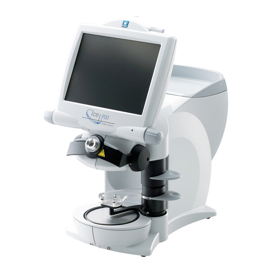
BEFORE USE: Configuration Configuration Front view Tray Touch pen Lens table (for Shape Im- Touch pen holder ager) Small-diameter Display panel lens holder Left jog dial Pilot lamp Cup holder Blocking arm Right jog dial Lens clamp Blocking system lever Lens table Lens clamp lever... - Page 13 BEFORE USE: Configuration Blocking arm When the arm is slightly lowered by hand, blocking starts automatically. Blocking can also be started by pressing the blocking start button on the Blocking screen. The blocking pressure is 2.5 kgf. Lens clamp Holds the lens. Lift the Lens clamp lever and place the lens with the convex surface up then lower the lever gently to hold the lens.
- Page 14 Slide the display tilt lever forward and backward by hand to set the display in one of 4 tilt angles. Power switch Turns on/off the Ice 900. Inlet Connect the detachable power cable. The inlet is equipped with a fuse holder.
- Page 15 This does not indicate a malfunction. ETHERNET: Standards on wiring, and access to the wiring to allow mutual accessing of various information processing terminals to the LAN. The Ice 900 transfers and receives data through 10/100BASE-T cables.
-
Page 16: Display
BEFORE USE: Display Display 1.3.1 Layout screen Screen for entering each data of lens layout and processing conditions. ■ Right or Left indication button PTN No. display Information bar Screen change tabs Tracer button Blocking switching button JOB#/PTN# Menu button Screen customize button Clock... - Page 17 BEFORE USE: Display Right or Left indication button Specify the right (R) and left (L) of the lens. Information bar Displays the current operation status or next operation. Tracer button Loads the shape data measured with the tracing unit to the display panel. This button is displayed only when the Mini Lab system is set.
- Page 18 BEFORE USE: Display Frame center mark Indicates the center of the lens shape (frame center). Optical center height [ Height of the optical center from the frame center (boxing center) Range [-15.0 to +15.0 mm (in increments of 0.1 mm)] and BT can also be entered.
- Page 19 BEFORE USE: Display When the Polish/SFB Setting parameter is set to Le/Lex: The selectable options are with polishing (Polish) and without polishing (None). The Polish option cannot be selected for glass lenses. When set to high curve, [Polish] cannot be set. (only when set to Le/Lex) When the Polish/SFB Setting parameter is set to Me/Se: The selectable options depend on whether safety beveling is “SFB”...
-
Page 20: Keyboard Screen (Blocker Lex, Mini Lab System)
BEFORE USE: Display 1.3.2 Keyboard screen (Blocker Lex, Mini Lab system) Screen for storing or loading JOB data (PTN data). ■ Press JOB#/PTN# on the Layout screen to display this screen. Or scan the barcode. ■ JOB#/PTN# Delete character Insert character Delete before character Close the keyboard button... -
Page 21: Keyboard Screen (Blocker Lab, Blocker Vca System)
BEFORE USE: Display 1.3.3 Keyboard screen (Blocker Lab, Blocker VCA system) Screen for receiving JOB data. ■ Press JOB#/PTN# on the Layout screen to display this screen. ■ JOB#/PTN# Delete character Insert character Delete before character Close the key- board button Hyphen input Alphanumeric key-... -
Page 22: Blocking Screen
BEFORE USE: Display 1.3.4 Blocking screen Screen for blocking. ■ Press the button on the Layout screen to display this screen. ■ Block [Blocking screen (Single)] This is the blocking screen when Single is selected for Type. Right or Left indication button JOB#/PTN# Camera brightness button Cup mark... - Page 23 BEFORE USE: Display Cup mark Displays the outer shape of the lens cup to be blocked. For the lens cup, in accordance with the lens edger specification to be used, set with the Cup mode parameter. The setting options are Half-eye, Pliable, Pliable/Mini, and Pliable/Nano. When Pliable/Mini or Pliable/Nano is selected, the shape changes to appropriate lens cup for small-diameter lens processing according to the shape size and layout value.
- Page 24 BEFORE USE: Display [Blocking screen (Multifocal)] Align the segment of the lens with the segment mark displayed on the screen and block in the ■ frame boxing center. The layout mode is fixed to Passive mode. ■ To display the Multifocal Blocking screen, select Multi for Type from the Blocking screen. ■...
- Page 25 BEFORE USE: Display [Blocking screen (Progressive)] Align the far vision eyepoint mark (or hidden marking) with the alignment scale and block the lens. ■ To display the Progressive Blocking screen, select Progressive for Type from the Blocking screen. ■ * The items not described in the following are the same as the Progressive Blocking screen [Single].
- Page 26 BEFORE USE: Display [Blocking screen (Demo lens)] For the demo lens, when the lens cannot be hold with the three pins as the lens is small, use the ■ small-diameter lens holder to block in demo lens mode. Align the markings of demo lens with the alignment scale then block the lens. ■...
-
Page 27: Hole Editor Screen
BEFORE USE: Display 1.3.5 Hole Editor screen Screen for editing hole data. The demo lens outline and the hole position are also detected. ■ Press the Hole Edit tab on the Layout screen to display this screen. ■ Right or Left indication button Mirror button Edit/Adjust button Hole setting invalid range... - Page 28 BEFORE USE: Display Mirror button Turns the mirror function on or off. Turn the mirror function on to drill the holes symmetrically in the right and left lenses. When the button color is light blue, the mirror function is on. When the button color is gray, the mirror function is off. Hole setting invalid range Indicates the area in which hole positions cannot be set.
- Page 29 BEFORE USE: Display Hole add buttons Specify the type of the hole to be added. Press with the touch pen the position where the hole of the type selected is to be added. A hole of the selected type is added in the pressed position on the screen. The selected type holes can be added successively until the selected button is pressed again or another button is pressed.
- Page 30 BEFORE USE: Display [Adjust screen] Magnify the camera image (still image) and hole image to specify the hole position and diameter ■ precisely. To display the Adjust screen, press on the Hole Editor screen. ■ Edit Edit/Adjust button Selected hole position move button Magnified shape outlline Hole position indica- tion...
- Page 31 BEFORE USE: Display [Shape Imager screen] For the Shape Imager function, place the demo lens or pattern on the lens table (for Shape Imager) ■ to measure (detect) the outline and hole position. To display the Shape Imager screen, press the tab on the Hole Editor screen.
- Page 32 BEFORE USE: Display Layout range mark Locates the lens in the range of rectangle. DBL entry field After measurement, the DBL entry field is displayed. Enter the DBL value. Alignment scale Align the marking on the demo lens, horizontal reference line, or pattern hole to this scale.
-
Page 33: Shape Editor Screen
BEFORE USE: Display 1.3.6 Shape Editor screen Screen for changing the imported lens shape data into the desired shape. ■ Press the Shape tab on the Layout screen to display this screen. ■ Eye mark button Eye image Shape dimension + and - input buttons Undo and redo buttons Fix area button... -
Page 34: Data Control Screen
BEFORE USE: Display 1.3.7 Data Control screen Screen for controlling data. A maximum of 500 folders, 500 data items per folder, and the total of ■ 30,000* or less data items can be saved in the internal memory. * The maximum number of data to be saved depends on the size of the data. Press the [Data] tab on the Layout screen to display this screen. -
Page 35: Ten-Key Pad Screen
BEFORE USE: Display Rename button Changes the selected data name. Data delete button Deletes the selected data. 1.3.8 Ten-key pad screen Screen for entering the numeric data such as FPD, PD, BT, size, and WD. ■ Instead of the ten-key pad, the numeric field of the item can be selected by the left jog dial and the ■... -
Page 36: Pop-Up Menu
BEFORE USE: Display 1.3.9 Pop-up menu Pressing the item button displays the pop-up menu. The desired item can be selected from the ■ pop-up menu. Instead of the pop-up menu, the numeric field of the item can be selected by the left jog dial and ■... -
Page 37: Labels And Indications On The Instrument
BEFORE USE: Labels and Indications on the Instrument Labels and Indications on the Instrument To call attention to users, some labels and indications are provided on the instrument. If labels are peeling off or characters are fading and becoming barely legible, contact NIDEK or your authorized distributor. -
Page 38: Checking Contents
BEFORE USE: Checking Contents Checking Contents Unpack the contents from the shipping carton and check them. The following are included in the standard configuration. • Main body • Power cord • Touch pen • RS-232C cable • Spare fuses (2 units) •... -
Page 39: Operating Procedures
“2.8 Blocking” (page 95) Processing lenses with the lens edger * Processing lenses with the lens edger by loading the JOB data from the Ice 900. * Lens processing “2.4.1 Operation in the Blocker Lex system” (page 41) Turning off the Ice 900... -
Page 40: Operation Flow Of The Mini Lab System
“2.8 Blocking” (page 95) Processing lenses with the lens edger * Processing lenses with the lens edger by loading the JOB data from the Ice 900. * Lens processing “2.4.2 Operation in the Mini Lab system” (page 44) Turning off the Ice 900... -
Page 41: Operation Flow Of The Blocker Lab System
“2.8 Blocking” (page 95) * Send JOB data to the host PC at the same time Processing lenses with the lens edger * Loading JOB data from the Ice 900 with the lens edger side * Lens processing Turning off the Ice 900... -
Page 42: Operation Flow Of The Blocker Vca System
OPERATING PROCEDURES: Operation Flow 2.1.4 Operation flow of the Blocker VCA system Turning on the Ice 900 Entering JOB# “2.4.4 Operation in the Blocker VCA system” (page 49) Receiving JOB data “2.4.4 Operation in the Blocker VCA system” (page 49) * From the VCA server, receive JOB data. -
Page 43: Getting Started And Exiting
Confirm that the cables from the connected instruments are securely connected to the Ice 900, and the power for each instrument is turned on. See “4.2.1 Connection samples” (page 118) for the connecting method. Turn on ( | ) the power switch. -
Page 44: Data Saving, Loading, And Control
OPERATING PROCEDURES: Data Saving, Loading, and Control Data Saving, Loading, and Control 2.3.1 For JOB, PTN, TMP data Contents of JOB data Traced data, all processing conditions, and layout information are all stored in the JOB data. Contents of PTN data Traced data, FPD (DBL), size, passive/active, lens material, lens type, frame type, polishing process- ing, and safety beveling data are all stored in the PTN data. - Page 45 OPERATING PROCEDURES: Data Saving, Loading, and Control Applying PTN# • The brand name becomes the folder name. When the folder for the brand name specified does not exist, the folder is automatically created. • The PTN# is specified by “(brand name) – (number)”. A maximum of 16 digits including the hyphen (-) may be specified.
-
Page 46: Loading Job Data Saved In The Ice 900
OPERATING PROCEDURES: Data Saving, Loading, and Control 2.3.3 Loading JOB data saved in the Ice 900 Loading data to the Data Control screen Press the Data tab on the Layout screen to display the Data Control screen. Select a file from the Data Control screen. -
Page 47: Loading Ptn Data Saved In The Ice 900
OPERATING PROCEDURES: Data Saving, Loading, and Control 2.3.4 Loading PTN data saved in the Ice 900 The Ice 900 can save the shape data (PTN) of two-point frames or such that are used repeatedly ■ used as stored shapes. For blocking, load the PTN data saved in the internal memory instead of tracing. -
Page 48: Data Control
OPERATING PROCEDURES: Data Saving, Loading, and Control 2.3.5 Data control The Data Control screen is the screen that controls the shape data. On this screen, data name ■ may be changed and data can be moved or backed up to an optional USB flash drive. The folder and data can be selected by the touch pen. - Page 49 OPERATING PROCEDURES: Data Saving, Loading, and Control A display of the folder list. The folder can be selected by the touch pen or left jog Folder list dial. JOB_DATA and TMP_DATA folders cannot be selected with the jog dial. Pressing this button sorts the folders in ascending order and descending order. Ascent/descent button JOB_DATA and TMP_DATA folders are fixed.
- Page 50 Press the Data tab on the Layout screen to display the Data Control screen. Insert the USB flash drive into the USB flash drive port of the Ice 900 rear side. The USB backup button is displayed. USB backup button Press the USB backup button.
-
Page 51: Operating Procedures
When tracing with the Lex 1000 built-in tracing unit 1) Trace frames or pattern with the Lex 1000. 2) After tracing, the traced data is automatically transferred from the Lex 1000 to Ice 900 and displayed on the Layout screen. - Page 52 OPERATING PROCEDURES: Operating Procedures For processing conditions, see “2.5.1 Setting processing conditions” (page 51). Specify the right (R) and left (L) of the lens layout. For entering layout, see “2.5.3 Entering layout data for single vision lenses” (page 61) to “2.5.5 Entering layout data for progressive power lenses”...
- Page 53 (not processing mode). A data transfer request is sent to the Ice 900. 1) The Ice 900 receives a request from the Lex 1000. It sends the data with the associated JOB# to the Lex 1000.
-
Page 54: Operation In The Mini Lab System
OPERATING PROCEDURES: Operating Procedures 2.4.2 Operation in the Mini Lab system In the Mini Lab system, data is controlled by the Ice 900 as data server. ■ Connect the Ice 900, LT-900, and ME-1000 to configure the system. ■ Before blocking, load the traced data or JOB/PTN data, then set processing conditions and enter ■... - Page 55 OPERATING PROCEDURES: Operating Procedures Specify the right (R) and left (L) of the lens layout. For entering layout data, see “2.5.3 Entering layout data for single vision lenses” (page 61) to “2.5.5 Entering layout data for progressive power lenses” (page 72). •...
- Page 56 1) Load JOB# with the ME-1000 barcode scanner in standby mode (not processing mode). A data transfer request is sent to the Ice 900. 2) The Ice 900 receives a request from ME-1000. It sends the data with the associated JOB# to the ME-1000.
-
Page 57: Operation In The Blocker Lab System
■ After blocking, the JOB data is automatically transferred to the host PC. ■ Turn on ( | ) the power switch to activate the Ice 900. For starting procedures, see “2.2 Getting Started and Exiting” (page 33). Enter JOB#. - Page 58 1) Load JOB# with the ME-1000 barcode scanner in standby mode (not processing mode). A data transfer request is sent to the Ice 900. 2) The Ice 900 receives a request from the ME-1000. It sends the data with the associated JOB# to the ME-1000.
-
Page 59: Operation In The Blocker Vca System
In the Blocker VCA system, JOB data is saved and controlled by an external host PC. ■ Perform only blocking with the Ice 900. ■ Turn on ( | ) the power switch to activate the Ice 900. For starting procedures, see “2.2 Getting Started and Exiting” (page 33). Enter JOB#. JOB#/PTN#... - Page 60 1) Load JOB# with the ME-1000 barcode scanner in standby mode (not processing mode). A data transfer request is sent to the Ice 900. 2) The Ice 900 receives a request from the ME-1000. It sends the data with the associated JOB# to the ME-1000.
-
Page 61: Setting Processing Conditions And Entering Layout Data
OPERATING PROCEDURES: Setting Processing Conditions and Entering Layout Data Setting Processing Conditions and Entering Layout Data Before setting processing conditions and entering layout data, perform tracing or load the traced ■ data. Entering layout data and setting processing conditions 2.5.1 Setting processing conditions As the processing conditions, set the lens material, frame type, processing mode. - Page 62 OPERATING PROCEDURES: Setting Processing Conditions and Entering Layout Data For details, see “1.3.9 Pop-up menu” (page 26). • CR39 (general plastic) • Hi-index (High index plastic) • Polyca. (polycarbonate) • Acrylic (Acrylic resin) • Trivex (a plastic that tends to meld during processing) •...
- Page 63 OPERATING PROCEDURES: Setting Processing Conditions and Entering Layout Data Processing mode With the processing mode button to the right of the frame type button, specify the processing contents for each frame type. Processing mode Processing contents Frame type Auto No bevel guided processing mode Guide With bevel guided processing mode According to the lens edger,...
- Page 64 OPERATING PROCEDURES: Setting Processing Conditions and Entering Layout Data High base curve auto processing, high base curve guided processing When Metal or Plastic is selected for the frame type, HC Auto or HC Guide processing can be ■ selected. If Active mode is selected, the layout mode automatically changes to Passive mode. Selecting HC Auto or HC Guide sets safety beveling off automatically.
- Page 65 OPERATING PROCEDURES: Setting Processing Conditions and Entering Layout Data Polishing Select a polishing mode. The selectable options depend on the connected lens edger. When the Polish/SFB Setting parameter is set to Le/Lex: Press the polishing button. Pressing the polishing button toggles between None and Polish.
- Page 66 OPERATING PROCEDURES: Setting Processing Conditions and Entering Layout Data Safety beveling Select a safety beveling mode. The selectable options depend on the connected lens edger. When the Polish/SFB Setting parameter is set to Le/Lex: Press the safety beveling button. Pressing the safety beveling button toggles between None and SFB.
- Page 67 • Soft processing mode is set to off with the button partial display Processing mode button • For soft processing in the Ice 900, the software version of the lens edger must be compatible. • Setting this mode applies soft processing automatically during lens processing.
-
Page 68: Grooving Settings
Grooving settings Grooving conditions can be set by the Ice 900. ■ • The setting is possible only when the Ice 900 is connected to an edger (ME-1000, Lex 1000/Lex Drill system or SE-9090 Express/AHM-1000 system) having the Grooving function. - Page 69 OPERATING PROCEDURES: Setting Processing Conditions and Entering Layout Data 2) Select the desired curve from the menu. Auto Computer-calculated curve Manually enter the desired curve. Curve Pressing the numeric button displays the ten-key pad. Enter the desired value. Front Front base curve (curve profiling the front surface of a lens) Rear Rear base curve (curve profiling the rear surface of a lens) Select the groove position on the edge by the ratio.
- Page 70 In the Ice 900, the groove specifications are set without measuring the lens curve. Therefore, the set specifications may the groove to be off the lens edge.
-
Page 71: Entering Layout Data For Single Vision Lenses
OPERATING PROCEDURES: Setting Processing Conditions and Entering Layout Data 2.5.3 Entering layout data for single vision lenses According to prescription, enter lens layout Active/Passive mode. ■ The layout data is displayed on the numeric button next to each item button. Pressing the numeric ■... - Page 72 OPERATING PROCEDURES: Setting Processing Conditions and Entering Layout Data The DBL (width between the nasal ends of the left and right frames) can also be entered instead of the FPD. Pressing the FPD button displays the pop-up menu. Press DBL to change to the DBL entry setting.
- Page 73 OPERATING PROCEDURES: Setting Processing Conditions and Entering Layout Data The monocular PD (1/2 PD) can be entered. It is possible to enter the distance from the bridge center to each eye separately. Optical center 1/2PD 1/2PD height Pressing the PD button displays the pop-up menu.
- Page 74 OPERATING PROCEDURES: Setting Processing Conditions and Entering Layout Data Enter the optical center height for the left- and right-eye lenses respectively. Press the numeric field of the (or PD , BT ) button to display the ten-key pad. Enter any value and press the button.
- Page 75 OPERATING PROCEDURES: Setting Processing Conditions and Entering Layout Data • The default displayed on the optical center height numeric button can be specified by setting the Optical center height parameter. Enter the size (enlarged or reduced lat- eral based size of lens shape) Enter an arbitrary value in the Size field if necessary.
- Page 76 OPERATING PROCEDURES: Setting Processing Conditions and Entering Layout Data Select whether to block the lens with a lens cup at the optical center or frame center. Pressing the Active (or Passive) button changes the layout mode between Active and Passive. Active The lens is blocked with the lens cup at the optical center.
- Page 77 OPERATING PROCEDURES: Setting Processing Conditions and Entering Layout Data Changes in the cup mark shape according to the layout setting When the Cup mode parameter is set to Pliable/Mini, or Pliable/Nano, the cup mark changes as fol- lows when the lens shape contacts the circle of the cup mark according to the layout setting. Setting Normal lens processing Small diameter lens processing...
- Page 78 OPERATING PROCEDURES: Setting Processing Conditions and Entering Layout Data Setting WD (width of the alignment scale) Press the WD numeric button to display the ten- key pad. Enter any value and press the but- ton. The numeric value can also be entered by the jog dial.
-
Page 79: Entering Layout Data For Multifocal Lenses
OPERATING PROCEDURES: Setting Processing Conditions and Entering Layout Data 2.5.4 Entering layout data for multifocal lenses For the multifocal lenses, the lens is blocked to the boxing center of the frame alinging the lens ■ position based on the segment base point (top line center of segment). According to prescription, enter lens layout data (FPD, near PD, and optical center height). - Page 80 OPERATING PROCEDURES: Setting Processing Conditions and Entering Layout Data Select either of the following. Enter the distance from the center point on the top line of the segment straight down to the point on the lens shape. Enter the height from the point level with the center of the segment on the top line straight down to the lowest point on the...
- Page 81 OPERATING PROCEDURES: Setting Processing Conditions and Entering Layout Data Setting WD (width of the segment mark of the multifocal lens) Pressing the WD numeric button displays the ten-key pad. Enter any value and press the button. The numeric value can also be entered by the jog dial.
-
Page 82: Entering Layout Data For Progressive Power Lenses
OPERATING PROCEDURES: Setting Processing Conditions and Entering Layout Data 2.5.5 Entering layout data for progressive power lenses For the progressive power lens, perform blocking aligning the lens position based on the ■ progressive lens far vision eyepoint, or hidden marking. According to prescription, enter lens layout data (FPD, PD, optical center height, and EP). - Page 83 OPERATING PROCEDURES: Setting Processing Conditions and Entering Layout Data Select Progressive for the lens type from the Layout screen. Enter FPD (or DBL). Enter the prescribed PD value in the PD (or 1/2PD) numeric field. Select a method to enter the optical cen- ter height.
- Page 84 OPERATING PROCEDURES: Setting Processing Conditions and Entering Layout Data Enter the height of the eye point. Press the PD (or BT ) numeric button to display the ten-key pad. Enter any value and press the but- ton. The numeric value can also be entered by the jog dial.
-
Page 85: Shape Editor Function
OPERATING PROCEDURES: Shape Editor Function Shape Editor Function This function changes the loaded lens shape data into the desired shape. ■ There are two entering methods for changes. ■ Changes in shape by changing the horizontal and vertical numeric values. ・... - Page 86 OPERATING PROCEDURES: Shape Editor Function Select a step to be applied when changing each length. Press the Step numeric button to dis- play the pop-up menu. Select the desired step button from Tenkey, 0.10, 0.25, or 0.50. As necessary, specify areas that are Fixed area not to be changed in shape.
- Page 87 OPERATING PROCEDURES: Shape Editor Function The screen returns to the numeric values condition and the set fixed area is displayed in yellow. • The numeric values for any area set not to be changed by the fixed area function are displayed in gray.
- Page 88 OPERATING PROCEDURES: Shape Editor Function Shape edit with numeric values 1) Select a step to be changed from the pop-up menu displayed by pressing the “Step” but- ton. Select the desired step button from Tenkey, 0.10, 0.25, or 0.50. 2) Press a numeric value to be changed.
- Page 89 OPERATING PROCEDURES: Shape Editor Function 2) Lifting the touch pen from the screen after dragging confirms the shape edit and displays the post- change numeric values. 3) Check the post-change shape on the screen. • The cross in solid lines represents the frame center of the original shape data. Once the shape is changed, it is updated but the frame center (cross) is not be updated.
-
Page 90: Drilling Settings
OPERATING PROCEDURES: Drilling Settings Drilling Settings It is possible to enter the specifications related to the drilling from the Ice 900. Lens outline and hole ■ position can be detected from the demo lens. Attach the lens table (for Shape Imager) to the instrument and place the demo lens or pattern. - Page 91 OPERATING PROCEDURES: Drilling Settings Hole position coordinate Press the hole position coordinate button on the Hole Editor screen. There are six types of coordinate display methods according to the selection of the horizon- tal and vertical reference positions. The method can be selected according to each hole. Change the hole position with the ten-key pad displayed by pressing each numeric field.
- Page 92 OPERATING PROCEDURES: Drilling Settings Hole angle Set the angle with the hole angle button. Pressing the button changes the settings in the following order. • Auto • Angle • X-Y • X Auto • Curve Only Auto, Angle, or Curve is selectable when the paired, notched or counterbored holes are selected.
- Page 93 OPERATING PROCEDURES: Drilling Settings Group Specify the group number to drill multiple parallel holes. When hole 1 and hole 3 are Pressing the Group numeric button displays the set to the same group, ten-key pad. Enter the group number and press those holes are drilled in button.
- Page 94 OPERATING PROCEDURES: Drilling Settings Hole type selection and position specification Select the hole type among the nine hole add buttons. Hole add buttons Setting and positioning of hole Setting of hole size Diameter Hole diameter Normal circular hole. Simple hole Specify the hole center position.
- Page 95 OPERATING PROCEDURES: Drilling Settings Paired holes Notched hole The reference is the The notch is automatically center of the hole nearer set to the shape edge. to the frame center. Notch height (Hole diameter) The reference is the hole center position.
-
Page 96: Attaching The Lens Table (For Shape Imager)
OPERATING PROCEDURES: Drilling Settings 2.7.2 Attaching the lens table (for Shape Imager) Lift the blocking system lever upward by hand. Turn the whole lens measurement part until it stops in the direction of arrow as shown in the figure on the right. The screen changes to the Shape Imager screen. -
Page 97: Preparation For Demo Lenses
OPERATING PROCEDURES: Drilling Settings 2.7.3 Preparation for demo lenses Mark a demo lens with a lensmeter to indicate its horizontal reference line. Clean the surface and edge of the demo lens, lens table (for Shape Imager), and reflec- tion protective plate with a dry soft cloth. •... -
Page 98: Measuring Demo Lenses (With Marking)
OPERATING PROCEDURES: Drilling Settings 2.7.4 Measuring demo lenses (with marking) Attach the lens table (for Shape Imager) to the Ice 900. The Shape Imager screen is automatically displayed. For confirmation procedures, see “2.7.2 Attaching the lens table (for Shape Imager)” (page 86). - Page 99 OPERATING PROCEDURES: Drilling Settings When the measurement is completed, the detected outline is displayed in white solid line and hole is displayed in pink dashed line on the screen. When the outline or marking cannot be detected, press the button to Cancel Cancel perform the operation from step 6.
- Page 100 OPERATING PROCEDURES: Drilling Settings After specifying the hole position, press Selected hole position move button button. Edit The status changes from the hole position addition to the hole position precise setting. The (red) hole area selected when Edit is pressed is magnified displayed. •...
- Page 101 OPERATING PROCEDURES: Drilling Settings Drag the paired (or notched) hole position displayed in green. • The value on the Diameter numeric button is also applied to the diameter of the paired holes or the width of notched holes. 5) Specify the hole depth as necessary. 6) Specify the group as necessary.
- Page 102 OPERATING PROCEDURES: Drilling Settings To save the shape data, press the JOB#/PTN#. After entering the JOB# or PTN# with displayed keyboard, press button to save the data.
-
Page 103: Measuring Patterns
OPERATING PROCEDURES: Drilling Settings 2.7.5 Measuring patterns The following steps 1 and 2 differ from steps 3 and 4 of 2.7.4 Measuring demo lenses (with ■ marking). All other procedures are the same. Press the button. Square scales for pattern Horizontally center the pattern refer- ence holes in the square scales for pat- tern on the screen. -
Page 104: Measuring Demo Lenses (Manual Alignment Mode)
OPERATING PROCEDURES: Drilling Settings 2.7.6 Measuring demo lenses (Manual Alignment mode) The following steps 1 and 2 differ from steps 3 and 4 of 2.7.4 Measuring demo lenses (with ■ marking). All other procedures are the same. Manually align the marking on the demo lens, horizontal reference line, or pattern hole to the scale ■... -
Page 105: Blocking
OPERATING PROCEDURES: Blocking Blocking Before blocking, perform tracing or load the traced data, then enter processing conditions and ■ layout data. • Before starting blocking, do not insert hands into the lens clamp. CAUTION After blocking, keep the hands away from the instrument as the lens clamp lowers and blocking arm rotates to return to the original position. - Page 106 OPERATING PROCEDURES: Blocking When using the half eye lens cups, use the double-coated adhesive pad for half eye lens cups. When using the normal double-coated Trim away. Double-coated adhe- adhesive pad, trim away the excess part sive pad for half eye along the edge of the cup.
- Page 107 OPERATING PROCEDURES: Blocking For single vision lenses Move the lens marks into the screen alignment scale so that they are roughly aligned to be horizontal. Lens mark • Press the button to display the screen in actual size and determine whether or not the lens outline sufficiently matches the entered layout conditions.
- Page 108 OPERATING PROCEDURES: Blocking For progressive power lenses For the progressive power lens, align the far vision eyepoint mark “+” to “+” on the screen and place the lens hori- zontal reference lines (or hidden mark- ing) are horizontal. Far vision eyepoint mark •...
- Page 109 OPERATING PROCEDURES: Blocking • Pressing the slow blocking button Blocking start button performs blocking in slow speed. Slow blocking button The blocking arm remains rest at the lowest position. When the OK button for “Complete blocking” displayed on the screen is pressed, the blocking arm returns to the upper position.
-
Page 110: Blocking Demo Lenses (Use The Small-Diameter Lens Holder)
OPERATING PROCEDURES: Blocking 2.8.1 Blocking demo lenses (use the small-diameter lens holder) When blocking demo lenses before tracing them, mark the lenses with a lensmeter beforehand. ■ When blocking demo lenses, it is unnecessary to load lens shapes, enter processing conditions ■... - Page 111 OPERATING PROCEDURES: Blocking Place the demo lens on the small-diam- eter lens holder with the convex side up. Align the lens position. Align the middle marking with the cen- ter of the alignment scale. Ensure that the markings are not askew.
-
Page 112: Initial Screen Customize Function
OPERATING PROCEDURES: Initial Screen Customize function Initial Screen Customize function This function sets the items on the Layout screen, Hole Editor screen, and Shape Editor screen ■ displayed when the power is turned on. When the factory settings on the Layout screen, Hole Editor screen, and Shape Editor screen differ ■... - Page 113 OPERATING PROCEDURES: Initial Screen Customize function Procedures Perform the following operations to save the screen. Display the screen to be saved as the initial settings. Change each item to the desired setting. Press the screen customize button. The operation procedures on the Lay- Screen customize button out screen are the same on the Hole Editor screen and Shape Editor...
-
Page 114: 2.10 Daily Checks
Check after use 1) Is the power turned off? 2) Is the Ice 900 dirty or damaged? 3) Are all the accessories accounted for and free from damage? Operator’s manual: 1 volume Power code: 1 unit... -
Page 115: Maintenance
MAINTENANCE Troubleshooting In the event that the Ice 900 does not work correctly, then troubleshoot with the following table ■ before contacting NIDEK or your authorized distributor. Symptom Action • Confirm that the power cord is properly connected. • Confirm that the voltage applied to the outlet is within the range specified. -
Page 116: Replacing Fuses
MAINTENANCE: Replacing Fuses Replacing Fuses If the Ice 900 is not started even though the power switch is turned on, the fuses may be blown. ■ Replace the fuses with spare ones. The two spare fuses are under the tray. -
Page 117: Setting Clock
MAINTENANCE: Setting Clock Setting Clock Display the Parameter screen. Press the Menu button on the Layout screen. Pressing the clock indication on the Layout screen directly displays the Clock screen. Press the Clock tab to display the Clock screen. The present year, month, day, time and Set buttons are displayed on the Clock screen. -
Page 118: Adjusting The Cup Holder
MAINTENANCE: Adjusting the Cup Holder Adjusting the Cup Holder If the plunger inside the cup holder becomes loose or worn out, the cup holder may not hold the lens cup securely. To tighten the plunger, insert the hexagonal-head wrench into the hole at the top of the cup holder, and turn the plunger. -
Page 119: Cleaning
The dirt on the reflection protective plate and lens table (for Shape Imager) affects the performance of the Ice 900 directly. Be sure not to get dirt or fingerprints on the reflection protective plate. Should the plate become dirty, clean the glass with dry soft cloth. -
Page 120: List Of Consumables
8040202155 218001.MXP (1A 250 V 5X20 mm) * After replacing consumables, restock them. Lens cup The following lens cup can be used for the Ice 900. Suction cup and full-eye lens cup cannot be used. Part name Part number Note... -
Page 121: Connection And Settings
CONNECTION AND SETTINGS Setting Parameters The parameters can be changed according to the needs of the operator. ■ Display the Parameter screen. Press the Menu button on the Layout screen. Press the tab of the desired parameter to select and change the setting. The parameter setting is shown on the button. - Page 122 CONNECTION AND SETTINGS: Setting Parameters [Parameter items and setting contents: general settings] 1) Language: English/Other Factory setting: English This parameter sets the language displayed. Select from English or Other. 2) Display brightness adjustment: 0 (dark) to 100 (bright) Factory setting: 100 Adjusts the brightness of the display.
- Page 123 3) My ID: 1 to 65535 Factory setting: 32 This parameter sets the ID No. for the Ice 900. When multiple Ice 900 units are connected in a network, set any number from 1 to 65535 as an identification number.
- Page 124 CONNECTION AND SETTINGS: Setting Parameters 7) Initialization session (VCA download): Preset, Auto Factory setting: Auto This parameter is effective only when the system setting is Blocker VCA. 8) VCA type: VCA-B, VCA-C Factory setting: VCA-B This parameter is effective only when the system setting is Blocker VCA. [Parameter items and setting contents: default value] 1) Optical center height: -5.0 to +5.0 mm...
- Page 125 CONNECTION AND SETTINGS: Setting Parameters [Parameter items and setting contents: block settings] 1) Block count: 0 to 999999999 Factory setting: 0 This parameter shows the numbers of blocked lenses. To clear the number of blocked lenses, press and hold the Block count display and select the Yes button when the “Clear the block counter.
- Page 126 CONNECTION AND SETTINGS: Setting Parameters 5) Lens holding time (sec.): 0.0 to 3.0 Factory setting: 0.0 This parameter is for setting the time period for the blocking arm to remain at rest at the low- est position in the range of 0.0 to 3.0 seconds. By setting the proper holding time, the lens cup attached condition can be checked when blocking the super water repellent lens.
- Page 127 CONNECTION AND SETTINGS: Setting Parameters 3) Flute length (Drill length): 1.0 to 10.0 Factory setting: 6.0 Set the parameter in accordance with the flute length of the drill. The default value range is 1.0 to 10.0 mm in increments of 0.1 mm. 4) Restriction radius: 10.00 to 20.00 Factory setting: 16.00 Sets the radius in the hole setting invalid range.
-
Page 128: Connection
• Confirm that all instruments are turned off before connecting them to the Ice 900. CAUTION Operation flow of the Blocker Lex system In the most basic system, the Ice 900 connects with one or two units of Lex 1000. Ice 900 RS-232C... - Page 129 CONNECTION AND SETTINGS: Connection Mini Lab system In a small- or medium-scale system, the Ice 900 serves as a data server. Ice 900 (When connecting a lens edger) Ice 900 (When connecting two lens edgers) Ice 900 Ice 900 RS-232C...
- Page 130 CONNECTION AND SETTINGS: Connection Connecting to Ice 900 (Mini Lab) LAN cable ME-1000 cable Ice 900 EDGER 1 connector EDGER 2 connector TRACER connector BAR CODE connector BAR CODE EDGER 1 EDGER 2 TRACER Barcode scanner (optional) RS-232C cable LT-900...
- Page 131 CONNECTION AND SETTINGS: Connection Blocker Lab system In a large-scale system, the external PC serves as a data server via LAN port. LT-900 RS-232C cable Host PC LAN cable ME-1000 ME-1000 Lex 1000 LAN cable Ice 900 cable (optional) ME-1000 ME-1000 Lex 1000...
- Page 132 CONNECTION AND SETTINGS: Connection Connecting to Ice 900 (Blocker Lab) LAN (Ethernet) cable Ice 900 BAR CODE connector EDGER 1 EDGER 2 TRACER BAR CODE Barcode scanner (optional) LAN port...
- Page 133 Blocker VCA system Connect to the host PC with RS-232C cable via EDGER1 port. RS-232C cable (optional) Ice 900 Host PC Connecting to Ice 900 (Blocker VCA) Ice 900 EDGER 1 connector BAR CODE connector BAR CODE EDGER 1 EDGER 2 TRACER...
-
Page 134: Setting The Ice 900
Ice 900 before shipment. Do not change the factory settings. *3: Set these parameters in accordance with the network to which the Ice 900 is connected. *4: When the NIDEK-produced PC software is used, set the host port No. to “55555”. When the other... -
Page 135: Setting Connected Instruments
Ice 900 before shipment. Do not change the factory settings. *2: Set these parameters in accordance with the network to which the Ice 900 is connected. *3: Set the parameters on the screen for servicing. Ask NIDEK or your authorized distributor for reset- ting of the above parameters. - Page 136 *2: Grooving setting and Bevel Guided setting cannot be sent to the Le 1000. *3: Set these parameters in accordance with the network to which the Ice 900 is connected. *: When the Ice 900 setting is Blocker VCA, contact NIDEK or your authorized distributor.
- Page 137 *2: Set these parameters in accordance with the network to which the Ice 900 is connected. *3: When the Ice 900 or NIDEK-produced PC software is used, set the host port No. to “55555”. When the other software is used, set the host port No. to the port No. of the used software.
- Page 138 *: When the Ice 900 setting is Blocker VCA, contact NIDEK or your authorized distributor. *: Blocker Lex cannot be connected. Setting of the LT-900 To directly connect the LT-900 to the Ice 900, connect the LT-900 to the TRACER port of the Ice 900. Parameter Mini Lab...
-
Page 139: Specifications And Accessories
SPECIFICATIONS AND ACCESSORIES Specifications Blocking Function • Method Imaging of reflected image • Maximum lens diameter 85 mm in diameter • Blocking Accuracy Position ±0.5 mm Axis angle ±1º Blocking pressure 2.5 kgf ±0.5 kgf Layout range • 30.00 to 99.50 mm •... -
Page 140: Other Functions
SPECIFICATIONS AND ACCESSORIES: Specifications Shape Imager Function • Measuring outer shape of the demo lens Measurement range 65.5 × 49.0 mm ±1.5 mm Circumference measurement accuracy ±0.15 mm (when NIDEK specification jig 45 mm in diameter is used) • Specification of hole position In increments of 0.01 mm •... - Page 141 SPECIFICATIONS AND ACCESSORIES: Specifications Environmental conditions (during use) • Temperature 5 to 40ºC (41 to 104ºF) • Humidity 5 to 31ºC (41 to 88ºF): 30 to 80% The minimum acceptable relative humidity is 30% for the temperature range of 31ºC to 40ºC. The maximum acceptable relative humidity is 80% for temperatures up to 31ºC which decreases linearly after that to 50% relative humidity at 40ºC.
-
Page 142: Standard Configuration
SPECIFICATIONS AND ACCESSORIES: Standard Configuration Standard Configuration 5.2.1 Standard accessories • Power cord 1 unit • Touch pen 1 unit • Communication cable (RS-232C) 1 unit • Spare fuse 2 units • Lens table (for Shape Imager) 1 unit • Small-diameter lens holder 1 unit •... -
Page 143: Index
INDEX Folder delete button ......24 Numerics Folder list ........24 1/2PD . - Page 144 INDEX: Lens table (for Shape Imager) .....3 Tracer button ........7 Lens type .
Need help?
Do you have a question about the Ice 900 and is the answer not in the manual?
Questions and answers