Table of Contents
Advertisement
Advertisement
Table of Contents

Related Manuals for Nidek Medical LT-980


Summary of Contents for Nidek Medical LT-980
- Page 1 Satellite Tracer OPERATOR’S MANUAL OPERATOR’S MANUAL...
- Page 2 Original instructions NIDEK CO., LTD. : 34-14, Maehama, Hiroishi-cho, Gamagori, Aichi 443-0038, Japan (Manufacturer) Telephone: +81-533-67-6611 Facsimile: +81-533-67-6610 NIDEK CO., LTD. : 3F Sumitomo Fudosan Hongo Bldg., 3-22-5, Hongo, (Tokyo Office) Bunkyo-Ku, Tokyo 113-0033, Japan Telephone: +81-3-5844-2641 Facsimile: +81-3-5844-2642 NIDEK INCORPORATED : 47651 Westinghouse Drive, Fremont, California 94539, U.
- Page 3 Before Use This OPERATOR’S MANUAL contains information necessary for the operation of the NIDEK Satellite Tracer Model LT-980. This manual includes operating procedures, safety precautions, specifications, and information about accessories and mainte- nance. This manual is necessary for proper use. Especially, the safety precautions and operating procedures must be thoroughly understood prior to the operation of the instrument.
-
Page 4: Table Of Contents
Table of Contents 1. CAUTIONS ......... . . 1 1.1 For Safe Use - - - - - - - - - - - - - - - - - - - - - - - - - - - - - - - - - - - - - - - - - - - - - - - - - - -1 1.2 Safety Precautions... - Page 5 3.3.5 Demo lens tracing - - - - - - - - - - - - - - - - - - - - - - - - - - - - - - - - - - - - - - - - - - - 50 3.3.6 Stopping tracing - - - - - - - - - - - - - - - - - - - - - - - - - - - - - - - - - - - - - - - - - - - - 51 3.4 After use...
-
Page 7: Cautions
CAUTIONS For Safe Use BEFORE USE, READ THIS MANUAL. Operation and maintenance of the instrument are under the administrative responsibility of the user. The cautions for safety and operating procedures must be thoroughly understood before using the instrument. Keep this manual handy for reference. Safety Precautions In this manual, a signal word is used to designate the degree or level of safety alert- ing. -
Page 8: Usage Precautions
CAUTIONS: Usage Precautions Usage Precautions Before use CAUTION • Do not use the instrument for any purposes other than the intended purpose. NIDEK is not responsible for accidents or malfunctions caused by misuse. For the intended purpose of the instrument, see “2.1 Outline of the Instrument” (page 8). •... - Page 9 CAUTIONS: Usage Precautions During use CAUTION • Only personnel authorized by NIDEK or a NIDEK distributor are allowed to disassemble or touch the interior of the instrument. Electric shock or malfunction may result. • In the event of smoke or strange odors, immediately turn off the instrument and disconnect the power plug from the wall outlet.
- Page 10 CAUTIONS: Usage Precautions Maintenance CAUTION • Be sure to check before use and after use. It is recommended to have regular maintenance checks every two years. Regular checks must be performed by qualified personnel. Ask NIDEK or your authorized distributor for details.
- Page 11 CAUTIONS: Usage Precautions Disposal CAUTION • Follow the local ordinances and recycling regulations regarding disposal or recycling of the compo- nents. It is recommended to commission the disposal to a designated industrial waste disposal contractor. Inappropriate disposal may contaminate the environment. •...
- Page 12 CAUTIONS: Usage Precautions...
-
Page 13: Introduction
Connecting the LT-980 and server PC using the STD communication - - - - - - - - - - - - - - - 37 Connecting the LT-980 and server PC using the VCA format communication Installing the USB driver for Windows 7... -
Page 14: Outline Of The Instrument
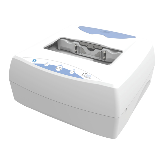
INTRODUCTION: Outline of the Instrument Outline of the Instrument The NIDEK Satellite Tracer Model LT-980 is a frame tracer which measures the shape of spectacle frames (hereafter referred to as frames). It traces the shape of frames in three dimensions to measure the three-dimensional lens circumfer- ence . -
Page 15: Configuration
INTRODUCTION: Configuration Configuration [Top view] Fuses Standard frame Standard pattern Pattern setting unit 6 7 [Rear view] Power switch Upper slider Frames are fastened between the upper and lower sliders. Rim clips Hold the rims of frames. Two rim clips are provided for each upper and lower slider. Lower slider Frames are fastened between the upper and lower sliders. - Page 16 INTRODUCTION: Configuration Left-eye tracing button Left-eye tracing button Starts left-eye tracing. Both-eye tracing button Both-eye tracing button Starts both-eye tracing. Pressing this button during tracing stops tracing. See “3.3.6 Stopping tracing” (page 51). Right-eye tracing button Right-eye tracing button Starts right-eye tracing. Power inlet (fuse holder) This is where the power cord is connected.
-
Page 17: Labels And Symbols
INTRODUCTION: Labels and Symbols Labels and Symbols Cautionary labels are provided on the LT-980. If labels are curling up or characters fading and becom- ing barely legible, contact NIDEK or your authorized distributor. Indicates that caution must be taken. Refer to the operator's manual before use. - Page 18 INTRODUCTION: Labels and Symbols [Front view] [Rear view] For other than EU regions For EU regions See “Maintenance” (page 4) and “4.2 Replacing Fuses” (page 56). CE marking Indicates that the product conforms fully to the require- ments of the Machinery Directive (2006/42/EC). The CE marking is placed only on the product for EU re- gions.
-
Page 19: Packed Contents
INTRODUCTION: Packed Contents Packed Contents Unpack the contents from the shipping carton and check them. Part name Quantity Appearance Fuse 2 units Hexagonal wrench 1 unit Stylus cover 1 unit Standard pattern 1 unit Pattern setting unit 1 unit Standard frame 1 unit Frame support attachment 2 units... -
Page 20: Before First Use
INTRODUCTION: Before First Use Before First Use Perform the following in preparation for first use of the LT-980. Place the instrument on a stable table. Remove the cushion fastening the upper and lower sliders. Cushion Remove the bracket fastening the upper and 2 screws lower sliders. - Page 21 INTRODUCTION: Before First Use Attach the stylus cover by putting the tip of the stylus pin through the hole in its center. Stylus cover The picture to the right shows the stylus cover attached with the stylus pin through its center hole.
- Page 22 INTRODUCTION: Before First Use After confirming that the power switch is turned off , plug the power cord in the wall outlet. CAUTION • The electrical outlet must have a grounding terminal. Electric shock or fire may occur in the event of malfunction or power leakage Perform check before use.
-
Page 23: Removing And Storing Accessories
INTRODUCTION: Removing and Storing Accessories Removing and Storing Accessories Removing and storing accessories The storage space contains the standard frame, standard pattern, two frame support attachments, and two fuses. Store them in the storage space of the tracer to avoid loss or damage when not in use. Place a finger on the indentation of the Storage cover storage cover as shown in the figure to the... -
Page 24: Storing And Handling The Pattern Setting Unit
INTRODUCTION: Storing and Handling the Pattern Setting Unit Storing and Handling the Pattern Setting Unit Store the pattern setting unit in the storage space of the tracer to avoid loss or damage when not in use. Pattern setting unit 2.7.1 Removing and storing the pattern setting unit Storing the pattern setting unit in the tracer With the upper and lower sliders closed,... -
Page 25: Handling The Pattern Setting Unit
INTRODUCTION: Storing and Handling the Pattern Setting Unit 2.7.2 Handling the pattern setting unit The instrument is operated using a pattern such as for two point frames or a processed lens that was mounted in frames as a demo lens. Attaching a pattern Attaching a pattern to the pattern setting unit Confirm the orientation in which the pattern is attached to the pattern setting unit. - Page 26 INTRODUCTION: Storing and Handling the Pattern Setting Unit Attaching a demo lens Attaching a demo lens to the pattern setting unit Block the convex surface of a demo lens with a pliable cup. Mark the approximate center of the demo lens Lens table with a lensmeter.
- Page 27 INTRODUCTION: Storing and Handling the Pattern Setting Unit Fit the pliable cup on the demo lens to the hole of the pattern setting unit. Hole While pressing both ends of the pattern setting unit, push in the demo lens. Pliable cup Demo lens Release both ends of the pattern setting unit to lock the demo lens.
-
Page 28: Setting The Pattern Setting Unit To The Tracer
INTRODUCTION: Storing and Handling the Pattern Setting Unit 2.7.3 Setting the pattern setting unit to the tracer Setting the pattern setting unit to the tracer The pattern setting unit is fastened to the pattern setting unit support by magnet. Securing pins Pattern setting unit With the upper and lower sliders closed, remove the pattern setting unit. -
Page 29: Setting The Standard Frame To The Tracer
INTRODUCTION: Setting the Standard Frame to the Tracer Setting the Standard Frame to the Tracer Setting the standard frame to the tracer The circumference (162.83) is indicated on the front of the stan- Circumference dard frame. Store the standard frame in the storage space of the tracer to avoid loss or damage when not in use. -
Page 30: Handling The Standard Pattern
INTRODUCTION: Handling the Standard Pattern Handling the Standard Pattern Attaching the standard pattern to the pattern setting unit “A” is indicated on the front of the standard pattern. Store the standard pattern in the storage space of the tracer to A indication avoid loss or damage when not in use. -
Page 31: Tracer Calibration
INTRODUCTION: Tracer Calibration 2.10 Tracer Calibration Calibrate the tracer using the provided standard frame and stan- dard pattern. Standard frame: Calibration of frame tracing Standard pattern: Calibration of pattern tracing ∗ Standard frame It is recommended to calibrate the instrument for high accuracy before use. - Page 32 INTRODUCTION: Tracer Calibration Set the standard frame. With the side on which the circumference is indicated facing up, insert the upper grooves of the standard frame between the rim clips of the upper slider. See “2.8 Setting the Standard Frame to the Tracer”...
- Page 33 INTRODUCTION: Tracer Calibration Set the standard pattern. A indication on standard pattern Set the standard pattern with the side on which “A” is Pattern setting unit indicated facing towards the pattern setting unit. See “2.9 Handling the Standard Pattern” (page 24) and “2.7.2 Handling the pattern setting unit”...
-
Page 34: Installing The Usb Driver
PC. If the connection is made using the RS-232C cable, the USB driver does not need to be installed. • Before connecting the USB cable to the LT-980, be sure to install the USB driver on the PC. The installation procedure of the USB driver differs depending on the operating system (Windows XP 32 bits, Windows Vista 32 bits, Windows 7 32 bits / 64 bits) of the PC. - Page 35 [Finish]. Turn on the power switch of the LT-980. Connect between the LT-980 and PC using the USB cable. See “2.12 Connection” (page 36) The Found New Hardware Wizard screen appears. Select “No, not this time” and click [Next].
- Page 36 INTRODUCTION: Installing the USB Driver When the Hardware Installation screen appears, click [Continue Anyway]. When the Found New Hardware Wizard screen appears, click [Finish]. The Found New Hardware Wizard screen appears again. Select “No, not this time” and click [Next]. Select “Install the software automatically”...
- Page 37 INTRODUCTION: Installing the USB Driver When the Hardware Installation screen appears, click [Continue Anyway]. When the Found New Hardware Wizard screen appears, click [Finish]. ∗ Installation of the USB driver for Windows XP is now complete.
-
Page 38: For Windows Vista
INTRODUCTION: Installing the USB Driver 2.11.2 For Windows Vista Installing the USB driver for Windows Vista This is the procedure for when the operating system of the PC is Windows Vista. Prepare the provided driver CD and USB cable. • Start installation without the USB cable connected to the PC. Start the PC and log in as an administrator. - Page 39 [Finish]. Turn on the power switch of the LT-980. Connect the LT-980 and PC using the USB cable. After a short time, the driver is installed and the USB cable can be used. See “2.12 Connection” (page 36). ∗...
-
Page 40: For Windows 7
INTRODUCTION: Installing the USB Driver 2.11.3 For Windows 7 Installing the USB driver for Windows 7 This is the procedure for when the operating system of the PC is Windows 7. Prepare the provided driver CD and USB cable. • Start installation without the USB cable connected to the PC. Start the PC and log in as an administrator. - Page 41 [Finish]. Turn on the power switch of the LT-980. onnect the LT-980 and PC using the USB cable. After a short time, the driver is installed and the USB cable can be used. See “2.12 Connection” (page 36). ∗...
-
Page 42: Connection
2.12.1 STD connection Connecting the LT-980 and server PC using the STD communication This is the configuration in which the LT-980 communicates with a server PC using the NIDEK standard protocol. The server PC stores and manages data. The LT-980 traces frames or patterns, creates traces data, and then sends them to the server PC. -
Page 43: Vca Connection
2.12.2 VCA connection Connecting the LT-980 and server PC using the VCA format communication This is the configuration in which the LT-980 communicates with a server PC using the VCA standard protocol. The server PC stores and manages data. The LT-980 traces frames or patterns, creates traces data, and then sends them to the server PC. -
Page 44: Nidek Lan Connection
This is the configuration in which the server PC or Ice series serves as a data server. The LT-980 traces frames or patterns, creates traces data, and then sends them to the server PC. Connect the LT-980 to the NFS-100 using the RS-232C cable (NFS-100 supplied cable / 1 m). -
Page 45: Operating Procedure
OPERATING PROCEDURE Quick Task Index Identifying frame tracing types - - - - - - - - - - - - - - - - - - - - - - - - - - - - - - - - - - - - - - - - - - - - - 42 - - - - - - - - - - - - - - - - - - - - - - - - - - - - - - - - - - - - 41 Starting up or shutting down the instrument - - - - - - - - - - - - - - - - - - - - - - - - - - - - - - - - - - - - - - - - - 51... -
Page 46: Operation Flow
OPERATING PROCEDURE: Operation Flow This section describes the instrument start-up, tracing procedure, and daily checks. For connecting systems and transferring data, refer to the manual of the connecting device or server software. Operation Flow Power ON Tracing “3.3 Tracing” (page 42) “3.3.1 Frame tracing (both eyes, single eye)”... -
Page 47: Startup And Shutdown
The LT-980 is now ready for use. 3.2.2 Shutdown After confirming that the LT-980 is not in the process of tracing or communicating, turn off power. CAUTION • Never turn off the power switch during tracing. Failure of the tracer may result. -
Page 48: Tracing
OPERATING PROCEDURE: Tracing Tracing Identifying frame tracing types Tracing measures the shape of spectacle frames (hereafter referred to as frames) three-dimension- ally . In addition, patterns or demo lenses can be measured. Tracing may be conducted using the following methods. Select the desired method. Frame tracing (both eyes) Traces both eyes of general frames. -
Page 49: Frame Tracing (Both Eyes, Single Eye)
OPERATING PROCEDURE: Tracing 3.3.1 Frame tracing (both eyes, single eye) This is the procedure to trace both eyes or single eye (right eye or left eye) using general frames. • As distortion may occur and correct measurement cannot be obtained from frames with low stiffness, perform demo lens tracing. - Page 50 OPERATING PROCEDURE: Tracing Start both-eye tracing. Press . Tracing starts. When the frames are released, tracing is complete. Gently open the lower slider and remove the frames. • If is pressed while frames are being retraced after the stylus came off, two beeps may sound and tracing cancellation may not occur.
-
Page 51: Semiauto Tracing (Both Eyes, Single Eye)
OPERATING PROCEDURE: Tracing 3.3.2 Semiauto tracing (both eyes, single eye) This is the procedure to insert the stylus into the groove by hand when the stylus does not automatically run in the frame groove because the groove is not in the middle of rim such as for plastic frames. - Page 52 OPERATING PROCEDURE: Tracing Semiauto tracing (single eye) Tracing a single eye frame by semi-auto tracing Measures the frame shape of the right eye or left eye. The FPD (Frame Pupillary Distance) cannot be measured during semiauto tracing (single eye). Enter the FPD or DBL value manually from a PC or blocker.
-
Page 53: Goggle Type Frame Tracing
OPERATING PROCEDURE: Tracing 3.3.3 Goggle type frame tracing Tracing sharply warped frames When frames are sharply warped, the stylus may come off the groove during tracing. In such a case, fasten only one rim between the rim clips and perform goggle type frame tracing. The FPD (Frame Pupillary Distance) cannot be measured during goggle type frame tracing. - Page 54 OPERATING PROCEDURE: Tracing Set frames. As shown in the picture below, do not fasten the left rim between the rim clips but hold the left temple. Fasten the right rim between the rim clips, maintain the right rim level, and then align the middle of the right rim to the dotted line position.
-
Page 55: Pattern Tracing
OPERATING PROCEDURE: Tracing 3.3.4 Pattern tracing Tracing patterns for two-point frames or such Measures the pattern shape such as for two-point frames. Pattern setting The FPD (Frame Pupillary Distance) cannot be measured during unit pattern tracing. Enter the FPD or DBL value manually from a PC or blocker. -
Page 56: Demo Lens Tracing
OPERATING PROCEDURE: Tracing 3.3.5 Demo lens tracing Tracing frames of demo lenses or thin rim frames Traces a processed lens that was mounted in frames as a demo Pattern setting lens in the same manner as pattern tracing. unit Distortion may occur and correct measurement cannot be obtained from frames with low stiffness. -
Page 57: Stopping Tracing
OPERATING PROCEDURE: Tracing 3.3.6 Stopping tracing Stopping tracing before completion Follow the procedure below to interrupt tracing. Stopping frame tracing Press The stylus moves to the original position and the frames are released. Remove the frames. • If is pressed while frames are being retraced after the stylus came off, two beeps may sound and tracing cancellation may not occur. -
Page 58: After Use
OPERATING PROCEDURE: After use After use Perform check after use. See “3.5 Daily Checks” (page 53). Put the provided dust cover on the instrument. • When the instrument is not in use, turn off the power switch and put the dust cover on. If dust settles, it may affect the measurement accuracy. -
Page 59: Daily Checks
OPERATING PROCEDURE: Daily Checks Daily Checks Check the items in the following checklist before using the instrument. Also, perform the checks after use. If any abnormalities are found, it is the user’s responsibility to correct them. It is recommended that the following checklists be copied and used accordingly. Checklist before use Date Item... - Page 60 OPERATING PROCEDURE: Daily Checks...
-
Page 61: Maintenance
MAINTENANCE Troubleshooting In the event that the instrument does not work properly, attempt to correct the problem referring to the following table before contacting NIDEK or your authorized distributor. Symptom Remedy • Confirm that the power cord is properly connected. •... -
Page 62: Replacing Fuses
MAINTENANCE: Replacing Fuses Replacing Fuses If the instrument is not started even though the power switch is turned , the fuses may be blown. Replace the fuses with new ones. CAUTION • Before replacing fuses, be sure to turn off the power switch and disconnect the power cord from the wall outlet. -
Page 63: Cleaning
MAINTENANCE: Cleaning Cleaning When the cover or panel of the tracer becomes dirty, clean it with a soft cloth. For stubborn stains, soak the cloth in a neutral detergent, wring well, and then wipe. Finally dry with a soft, dry cloth. •... - Page 64 MAINTENANCE: List of Consumables...
-
Page 65: Specifications And Accessories
SPECIFICATIONS AND ACCESSO- RIES Specifications Tracing unit Automatic 3D binocular tracing • Tracing method • Frame tracing Measurement range • Shape width: 36 to 85 mm, shape height 18.4 to 66 mm, frame horizontal width: 113 to 180 mm • Maximum height from clamp midpoint: 23 mm •... -
Page 66: Other Functions
SPECIFICATIONS AND ACCESSORIES: Specifications Other functions • External communica- RC-232C compatible Two ports built-in tion PORT1 For connection with a PC or edger PORT2 For connection with the barcode scanner Port built-in Operating systems (English version) • Windows XP 32-bit •... -
Page 67: Accessories
SPECIFICATIONS AND ACCESSORIES: Accessories Accessories 5.2.1 Standard accessories Part name Quantity Appearance Fuse 2 units Hexagonal wrench 1 unit Stylus cover 1 unit Standard pattern 1 unit Pattern setting unit 1 unit Standard frame 1 unit Frame support attachment 2 units USB driver CD for Windows 1 unit RS-232C cable (3 m) -
Page 68: Optional Accessories
SPECIFICATIONS AND ACCESSORIES: Accessories 5.2.2 Optional accessories Part name Part number Appearance Barcode scanner 41266-E001 Contact NIDEK or your RS-232C cable (5 m, 10 m) authorized distributor. Contact NIDEK or your USB cable (3 m, 5 m) authorized distributor. -
Page 69: Index
INDEX Barcode scanner ......10 Upper slider ....... . . 9 Both-eye tracing . - Page 70 INDEX:...
Need help?
Do you have a question about the LT-980 and is the answer not in the manual?
Questions and answers