
Related Manuals for Nidek Medical AFC-330


Summary of Contents for Nidek Medical AFC-330
- Page 1 NON-MYDRIATIC AUTO FUNDUS CAMERA NON-MYDRIATIC AUTO FUNDUS CAMERA AFC-330 AFC-330 OPERATOR’S MANUAL OPERATOR’S MANUAL...
- Page 2 Original instructions NIDEK CO., LTD. : 34-14, Maehama, Hiroishi-cho, Gamagori, Aichi 443-0038, Japan (Manufacturer) Telephone: +81-533-67-6611 Facsimile: +81-533-67-6610 NIDEK CO., LTD. : 3F Sumitomo Fudosan Hongo Bldg., 3-22-5, Hongo, (Tokyo Office) Bunkyo-Ku, Tokyo 113-0033, Japan Telephone: +81-3-5844-2641 Facsimile: +81-3-5844-2642 NIDEK INCORPORATED : 47651 Westinghouse Drive, Fremont, California 94539, U.
- Page 3 Use this device properly and safely. BEFORE USE, READ THIS MANUAL. This operator’s manual includes operating procedures, safety precautions, and specifications for the NIDEK Non-mydriatic auto fundus camera, AFC-330. Cautions for safety and operating procedures must be thoroughly understood before using this device.
- Page 4 Usage precautions Safety of LED CAUTION • The device is a Class 1 LED product in accordance with IEC60825-1: 1993+A1: 1997+A2: 2001 and the LED used for the device is safe in expected use conditions including situations such as looking into the LED using an optical system. However, it is recommended to observe the following precautions when using the device: 1)Do not direct LED beams to human eyes when unnecessary.
- Page 5 CAUTION • Install the device in an environment where no contaminant such as corrosive gas, acid, or salt is contained in the air. Corrosion or malfunction of the device may result. • Avoid installing the device where it is exposed to direct air flow from an air conditioner.
- Page 6 CAUTION • Before carrying the device to another location, disconnect all the cords and cables. If the cords and cables get caught or stepped on, the device may fall, resulting in injury or failure. • Do not expose the LCD touch-screen to direct sunlight or intense ultraviolet rays. The LCD touch-screen may become damaged.
- Page 7 During Use CAUTION • Be sure to use accessories specified by NIDEK. Use of the accessories not specified by NIDEK may cause malfunctions or adverse events. • When turning off power to the device, do not turn off ( ) the power switch at first. Be sure to turn off the device power with the procedure described in “2.4.1 Usual finishing of operation”...
- Page 8 CAUTION • Before and after use, and before every patient, clean the parts that come into contact with the patient such as the forehead rest and chinrest with clean gauze or cloth dampened with rubbing alcohol. For severe stains, wipe with a clean cloth dampened with rubbing alcohol instead of wiping them repeatedly with a dry cloth.
- Page 9 CAUTION • Each time before connecting a USB flash drive to the device, be sure to check it for viruses. If the device is infected with a virus and any problem occurs, NIDEK does not assume responsibility or compensate for damages. •...
- Page 10 Patient environment The patient environment is the volume of space in which contact can occur between the patient and any part of the device or between the patient and any other person(s) touching the device. Use devices that comply with IEC60601-1 in the patient environment. If any device that does not comply with IEC 60601-1 is to be used, use an isolation transformer or common protec- tive grounding.
- Page 11 After use CAUTION • When the device is not in use, turn off power to the device and protect the objective lens from dust by covering it with the lens cap, then place the dust cover over the unit. • When disconnecting the power plug from the power outlet, turn off power to the device, then remove it making sure to always hold the power plug, not the cord.
- Page 12 Maintenance CAUTION • When the halogen lamp for eye observation, or the xenon flash lamp for image capture needs to be replaced, contact NIDEK or your authorized distributor. The device incorporates extremely high-voltage components. Opening the lamp house cover or replacing the lamp may result in electric shock. For replacement of parts, see “...
- Page 13 Connection to Network CAUTION • When connecting to peripheral equipment like a PC with LAN connector via a medical facility network, insert or connect an isolation transformer between medical electrical equipment and the networked device (such as HUB), or the networked device and any other electrical equipment.
-
Page 15: Table Of Contents
Table of Contents 1. BEFORE USE ........1 1.1 Device Outline . - Page 16 2.8.3 Focus bar ............103 2.9 Control Menu .
-
Page 17: Before Use
The NIDEK NON-MYDRIATIC AUTO FUNDUS CAMERA, AFC-330 captures fundus images using a built-in color CCD camera without the use of mydriatic agents. The AFC-330 is useful not only for oph- thalmology but also for fundus photography in medical examinations such as for diabetes. -
Page 18: Intended Use
BEFORE USE: Intended Use Intended Use The NIDEK Non-Mydriatic Auto Fundus Camera Model AFC-330 is an ophthalmic camera that is indi- cated for use in capturing images of the retina and the anterior segment of the eye. * When the device is used with NAVIS-EX, for which a separate operator’s manual is provided, the functions for image review, image processing, and exporting are available. -
Page 19: Device Configuration
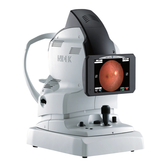
BEFORE USE: Device Configuration Device Configuration LCD panel 1. LCD touch-screen 2. Pilot lamp Image 3. Release button capturing unit Main unit 4. Joystick 5. Infrared filter lever Operation panel Base unit 1. LCD touch-screen An 8.4-inch color LCD touch-screen that allows operation of various functions with the buttons displayed on For the displayed contents, see “1.5 Screen Configuration”... - Page 20 BEFORE USE: Device Configuration 3. Release button Provides the following four functions: • Execution of image capture The flash is fired and the eye image is captured by the built-in CCD camera. • The same function as the OK/Auto transfer button or the retry button in the preview screen •...
- Page 21 BEFORE USE: Device Configuration Anterior eye illumination and LEDs for alignment 6. External fixation lamp (optional) 7. Spacer for anterior eye image capture Cap holder 8. Forehead rest 9. Objective lens 10. Eye level marker Objective lens cap 11. Chinrest Head rest 12.
- Page 22 BEFORE USE: Device Configuration 6. External fixation lamp The external fixation lamp is optionally available. When the external fixation lamp is connected to the device, it is recognized by the device and becomes available. For detailed operation, see “2.8.1 Fixation lamp mode” (Page 101). 7.
- Page 23 BEFORE USE: Device Configuration [Operation panel] 1. Observation illumination intensity knob 3. Anterior eye/fundus observation toggle button 4. Focus knob 5. Locking knob Min. Max. 2. Chinrest up/down buttons 1. Observation illumination intensity knob Turned to adjust the illumination intensity for fundus observation. Scale: Min., 1, 2,..8, 9, Max.
- Page 24 BEFORE USE: Device Configuration CAUTION • Never lock the main unit using the locking knob when the device is packed and transported. The device may be damaged by vibration and bumping. mark Locking knob Hole...
- Page 25 BEFORE USE: Device Configuration [Power switch and ports] 3. VGA port 4. Keyboard and mouse ports 1. Power switch 2. Power inlet 5. USB port 6. LAN port 1. Power switch Press the On ( ) side to turn on power to the device. When turning off power to the device, be sure to press the shutdown button at the top left of the LCD touch- screen, then wait for the instruction to turn off the power switch to appear before turning off the power switch.
-
Page 26: Screen Configuration
BEFORE USE: Screen Configuration Screen Configuration [Anterior eye observation screen - 1] 11. Vertical movement limit indicator 1. Patient list button 12. Left and right movement limit indicator 2. Captured eye indication 3. Eyelid and eyelashes mark 16. Patient register button 4. - Page 27 BEFORE USE: Screen Configuration 1. Patient list button Used to display the patient list screen that allows selection of the patient for whom images are to be captured, editing of the existing patient information, and registration of new patients. The ID and name of the patient being selected are shown in this button.
- Page 28 BEFORE USE: Screen Configuration 6. Chinrest limit indicator Indicates that the chinrest is at the limit of the vertical movement range. When this icon is displayed, the chinrest is at the upper limit of the vertical movement range. When this icon is displayed, the chinrest is at the lower limit of the vertical movement range. 7.
- Page 29 BEFORE USE: Screen Configuration 11. Vertical movement limit indicator Indicates that the image capturing unit is at the limit of the vertical movement range in the anterior eye and fundus observation screens. When this icon is displayed in the upper half of the screen, the image capturing unit is at the upper limit of the vertical movement range.
- Page 30 BEFORE USE: Screen Configuration 15. Small pupil photography mode toggle button Pressing this button toggles use of Small pupil photography mode between ON and OFF. (Black background): Small pupil photography mode is OFF (Usual image capture) The usual image capture is executed for an eye that satisfies the required pupil diameter (4.0 mm or larger in diameter).
- Page 31 BEFORE USE: Screen Configuration [Anterior eye observation screen - 2] 2. Anterior eye/fundus auto advance button 1. Auto tracking button 3. Auto focus button 4. Auto anti-misshooting button 1. Auto tracking button Used to toggle use of the auto tracking (enabled [two sensitivity levels] or disabled). When the device detects the cornea-reflected spots arranged in a circle in the anterior eye observation screen, the image capturing unit automatically moves up, down, right, left, forward, and backward to achieve a proper alignment.
- Page 32 BEFORE USE: Screen Configuration 2. Anterior eye/fundus auto advance button Used to toggle use of automatic advancement from the anterior eye observation screen to the fundus observation screen. When the automatic advancement is enabled, completing the alignment in the anterior eye observation screen automatically displays the fundus observation screen.
- Page 33 BEFORE USE: Screen Configuration When disabled Even if the patient’s eyelid is detected or the required pupil diameter is not satisfied (minimum pupil diameter in Small pupil photography mode) ( being displayed), image capture can be executed with the auto shot or by pressing the release button.
- Page 34 BEFORE USE: Screen Configuration [Anterior eye observation screen - 3] 1. Normal photography button 2. Stereo photography button 3. Panorama photography button 4. Anterior eye photography button 1. Normal photography button Used to enable Normal photography mode. When it is enabled, the button background is displayed in orange.
- Page 35 BEFORE USE: Screen Configuration [Anterior eye observation screen - 4] 1. Cornea-reflected spots 2. Working distance indicator 3. Target mark 6. Forward and backward move- ment limit indicator 4. Required pupil diameter mark 7. Electronic working dot 5. Minimum pupil diameter mark 1.
- Page 36 BEFORE USE: Screen Configuration 5. Minimum pupil diameter mark Indicates the minimum pupil diameter (3.3 mm-diameter dotted circle) in Small pupil photography mode. When the auto anti-misshooting is enabled , like the required pupil diameter mark, if the cornea- reflected spots are not detected, or the pupil edge is inside the required pupil diameter mark, the required pupil diameter mark and the minimum pupil diameter mark are displayed in pink.
- Page 37 BEFORE USE: Screen Configuration [Anterior eye observation screen - 5] 1. Focus gauge 2. Compensation lens 3. Flash intensity 4. Flash intensity up/down button 1. Focus gauge Serves as a guideline for focusing. In the fundus observation screen, activating the auto focus or rotating the focus knob moves the blue ball along the arc of the circle to show the degree of diopter adjustment.
- Page 38 BEFORE USE: Screen Configuration [Fundus observation screen] In Normal photography mode 1. Optical working dot charts 2. Orientation tab 3. Focus split 4. Fundus focus undetection mark 5. Anterior eye monitor 6. Split indicator 7. Focus bar Working distance indicator Target mark 8.
- Page 39 BEFORE USE: Screen Configuration 5. Anterior eye monitor Displays the anterior eye image in the fundus observation screen. It allows checking of a possible shift in alignment. 6. Split indicator Shows the amount of focus deviation in the fundus observation screen. Adjust the focus using the focus knob so that only a single line is displayed.
- Page 40 BEFORE USE: Screen Configuration [Preview screen] Displays captured image for confirmation immediately after image capture. 1. LCD angle check mark 2. Enlarge button 3. Reduce button 4. OK/Auto transfer button 5. Retry button 1. LCD angle check mark Indicates whether the LCD touch-screen is at an appropriate angle for confirmation of captured images. When the angle of the LCD touch-screen is not appropriate, captured images cannot be confirmed clearly.
- Page 41 BEFORE USE: Screen Configuration 4. OK/Auto transfer button Used to transfer the preview image to the connected external storage device such as a USB flash drive. After the preview image is transferred, the review screen appears. The same operation can be executed by selecting the button with the joystick and pressing the release button.
- Page 42 BEFORE USE: Screen Configuration [Thumbnail screen] Displays thumbnails of captured images for a patient. • Although the images displayed as thumbnails are temporarily saved in the device even when the device power is turned off, save necessary images in a USB flash drive using the transfer button before turning off the device power.
- Page 43 BEFORE USE: Screen Configuration 3. Image capture button When this button is pressed, the anterior eye observation screen appears in the same photography mode as used for the latest image capture. 4. Recapture button Used to display the anterior eye observation screen with the same image capture conditions as used for the image being selected with the thumbnail (same eye [left eye if the selected image is left eye] in same photography mode).
- Page 44 BEFORE USE: Screen Configuration 11. Print button Used to print the image being selected or reviewed when a printer is connected to the device. For details of connection or use, see “ Printer” (Page 129) and “3.1.2 Connection, disconnection, and use of printer”...
- Page 45 BEFORE USE: Screen Configuration 17. External device display Shows the icon of external devices connected to the device. : Displayed when a USB flash drive is connected. : Displayed when a PC is connected to the device via a LAN. : Displayed when a printer is connected to the device.
- Page 46 BEFORE USE: Screen Configuration [Captured image information] In the thumbnail or review screen, information of images such as whether the eye is the right eye or the left eye is shown. 1. Photography mode 2. Eye (right or left) 3. Transfer complete mark 4.
- Page 47 BEFORE USE: Screen Configuration 5. Number of images captured in the same photography mode Shows the total number of images of the same eye captured in the same photography mode, and the image number assigned to the image beginning with the newest image. Example: 2/3 Total number of images of the same eye captured in the same photography mode Second newest image...
- Page 48 BEFORE USE: Screen Configuration [Review screen] Displays the captured image immediately after image capture. Single image button Dual image button Side-by-side image button Right eye review button Left eye review button Reduce button Enlarge button Image scroll buttons In the review screen, the same buttons and information are displayed as in the thumbnail screen. •...
- Page 49 BEFORE USE: Screen Configuration [Photography settings menu] When the photography setting menu button is pressed, the Photography settings menu screen appears. 4. Operator register button 5. Control menu button 6. USB flash drive button 7. External device display 8. Close button Photography setting menu button 1.
- Page 50 BEFORE USE: Screen Configuration 2. Camera settings select buttons A maximum of three image capture conditions can be preset and saved as “CAM1”, “CAM2”, and “CAM3” for later use. : Default is CAM1. For setting of each button, see “ CAM1, CAM2, CAM3” (Page 117). These buttons do not appear and cannot be used in Low-light photography mode.
- Page 51 BEFORE USE: Screen Configuration : Displayed when a printer is connected to the device. When the printer is disconnected, this mark is not displayed. 8. Close button Used to close the Photography settings menu screen.
- Page 52 BEFORE USE: Screen Configuration [Patient information register screen] Pressing the patient list button displays the screen shown below. (When the Patient ID quick registration function is set to ON, the button changes to 8. Search button 9. Captured patient list search button 10.
- Page 53 BEFORE USE: Screen Configuration • Once any image was captured, past patient data cannot be restored unless the device is restarted. Pressing the button after image capture displays the message below. 2. Image capture button Pressing this button after selecting a patient displays the anterior eye observation screen for alignment and image capture.
- Page 54 BEFORE USE: Screen Configuration 7. Return button Used to display the anterior eye observation screen for the patient (shown in orange) selected in the patient information register screen. 8. Search button This button is shown in orange when the list of patients searched using the search condition setting button is displayed in the patient information register screen.
- Page 55 BEFORE USE: Screen Configuration 13. Down scroll button Used to go back a page if the patient list is shown in multiple pages. 14. Last page button Used to move to the last page if the patient list is shown in multiple pages. 15.
- Page 56 BEFORE USE: Screen Configuration [Control menu] Pressing the Control menu button in the Photography setting menu screen displays the Control menu screen. The menu is on two pages. Page 1/2: Main unit settings—For operation and display on the main unit Photography settings—For image capture conditions Page 2/2: External settings—For external device Other settings—For clock and version information...
-
Page 57: Labels And Symbols
BEFORE USE: Labels and Symbols Labels and Symbols To call attention to users, labels and indications are provided on the device. If labels are peeling off, characters are fading, or otherwise becoming illegible, contact NIDEK or your authorized distributor. Indicates that the operator is advised to refer to the related instructions in the operator’s manual. - Page 58 See “Before Use” (Page II), and the precaution of Step 6 (Page 47) in “1.8 Device and Software Setup” (Page 46). CE marking Indicates that the product conforms fully to the requirements of the Medical Device Directive (93/42/EEC). The AFC-330 is classified as a Class IIa according to the Medical Device Directive.
- Page 59 BEFORE USE: Labels and Symbols For Canada CLASS 1 LED PRODUCT AFC-330 Non-Mydriatic Auto Fundus Camera INPUT 100-240V〜 50/60Hz 150VA 38NNNN SER.NO. xxxx 34-14 MAEHAMA HIROISHI-CHO GAMAGORI AICHI 443-0038 JAPAN MADE IN JAPAN 15411-M823-C0 See “Before Use” (Page II), and the precaution of Step 6 (Page 47) in “1.8 Device and Software Setup” (Page 46).
- Page 60 BEFORE USE: Labels and Symbols Common See “Before Use” (Page II).
-
Page 61: Packed Contents
BEFORE USE: Packed Contents Packed Contents Remove the contents from the shipping carton, then check the contents. The following standard accessories are contained: • AFC-330 main body • Power cord • Dust cover • Chin rest paper • Chinrest paper pins •... -
Page 62: Device And Software Setup
BEFORE USE: Device and Software Setup Device and Software Setup Install the device in a place in accordance with the precautions in “Before Use”. The procedure below is explained with a USB flash drive connected to the device, which is the default setting for the device. - Page 63 BEFORE USE: Device and Software Setup 2) Adhere the cap holder on a appropriate place such as a Adhere side of the device. The cap holder is adhesive-backed. Adhere it after removing the paper backing. Place the objective lens cap on the objective lens when the device is not used, or on the cap holder when the device is used.
- Page 64 BEFORE USE: Device and Software Setup Turn on ( ) power to the device. The initial screen is displayed and the device is initialized. Wait (for about 45 seconds) until the initial screen changes to the anterior eye observation screen. The anterior eye observation screen is displayed.
- Page 65 BEFORE USE: Device and Software Setup Press the patient register button at the bottom of the patient information register screen. The new patient register screen is displayed. Image capture button Save button New patient register screen Input the patient information in the new patient register screen. Patient ID, Name, Sex, Date of birth, History (medical history), Race, Comments The ID is automatically assigned and appears in the Patient ID box.
- Page 66 BEFORE USE: Device and Software Setup Press the image capture button The anterior eye observation screen is dis- played for image capture. Preparation for image capture is complete.
- Page 67 BEFORE USE: Device and Software Setup Reference pages for the desired operation Desired operation Reference page Capturing fundus images when the patient's pupil is “2.5.4 Small pupil photography mode” (Page 76) small Stereo photography “2.5.1 Stereo photography mode” (Page 70) Panorama photography “2.5.2 Panorama photography mode”...
- Page 68 BEFORE USE: Device and Software Setup...
-
Page 69: Operating Procedure
OPERATING PROCEDURE Operation Overview The device can be used with a USB flash drive connected for storing captured images. The device may also be connected with a personal computer (PC) via a LAN or directly to the network of the med- ical facility via a LAN for storing and managing captured images. - Page 70 OPERATING PROCEDURE: Operation Overview Standard image capture procedure Turning on the device 2.2 Image Capture Preparation (Page 55) Turn on power to the device, and change the setting of the device as necessary. Image capture 2.3 Image Capture (Normal Photography Mode [Auto shot, No blink]) (Page 58) Select the patient and prepare for image capture.
-
Page 71: Image Capture Preparation
OPERATING PROCEDURE: Image Capture Preparation Image Capture Preparation This is the daily preparation procedure for the device with a USB flash drive connected to it, which is the default setting for the device. When using the USB flash drive, observe the instructions in “3.1 Connection of USB devices” (Page 139). - Page 72 OPERATING PROCEDURE: Image Capture Preparation Turn on power to the device. The initial screen appears on the LCD touch- screen. Initialization of the device is started. Wait (for about 45 seconds) until the initial screen changes to the anterior eye observation screen.
- Page 73 OPERATING PROCEDURE: Image Capture Preparation Perform preoperation check of the device. Perform the checks below prior to operation of the device. The main unit can be moved smoothly forward, backward, to the left and right using the joystick. The image capturing unit can be moved up and down by the joystick. ...
-
Page 74: Image Capture (Normal Photography Mode [Auto Shot, No Blink])
OPERATING PROCEDURE: Image Capture (Normal Photography Mode [Auto shot, No blink]) Image Capture (Normal Photography Mode [Auto shot, No blink]) Image capture is performed after selecting the desired patient from the patient information register screen. In non-mydriatic photography, the patient’s pupil needs to be dilated in a darkened place (a light level at which a newspaper can barely be read). - Page 75 OPERATING PROCEDURE: Image Capture (Normal Photography Mode [Auto shot, No blink]) If the name of the desired patient is not in the list, press the patient register button the bottom of the patient information register screen or at the top right of the anterior eye observation screen.
- Page 76 OPERATING PROCEDURE: Image Capture (Normal Photography Mode [Auto shot, No blink]) Forehead rest Eye level marker Chinrest up/down buttons Chinrest Perform alignment using the joystick so that the patient’s anterior eye is displayed on the LCD touch-screen. Make the (eight) cornea-reflected spots appear. When the eight cornea-reflected spots are detected, the alignment automatically proceeds as described below.
- Page 77 OPERATING PROCEDURE: Image Capture (Normal Photography Mode [Auto shot, No blink]) 1) The electronic working dot is displayed, and Required pupil Cornea-reflected spots diameter mark the auto tracking in the up, down, forward, backward, left, and right directions is acti- vated.
- Page 78 OPERATING PROCEDURE: Image Capture (Normal Photography Mode [Auto shot, No blink]) Check the captured image from a position at which neither of the LCD angle check marks on both sides of the preview screen are seen as a checkered pattern ( A captured image can be enlarged with the enlarge button .
- Page 79 OPERATING PROCEDURE: Image Capture (Normal Photography Mode [Auto shot, No blink]) If auto tracking stops before the alignment is complete <If the auto tracking in the up, down, left, and right directions stops before the anterior eye is displayed in the center of the screen>...
- Page 80 OPERATING PROCEDURE: Image Capture (Normal Photography Mode [Auto shot, No blink]) For the joystick movement amount, see the working distance indicator. Too close to the patient’s eye Pull the joystick to move the image capturing unit away from the patient’s eye. The alignment is optimum.
-
Page 81: Image Capture Without Automatic Functions
OPERATING PROCEDURE: Image Capture (Normal Photography Mode [Auto shot, No blink]) 2.3.2 Image Capture without automatic functions Image capture with Manual selected with the Auto/Manual toggle button All the auto functions are disabled. Because the auto shot is disabled, the eyelid and eyelashes mark is not displayed. - Page 82 OPERATING PROCEDURE: Image Capture (Normal Photography Mode [Auto shot, No blink]) When proper alignment is achieved, press the anterior eye/fundus observation toggle button to display the fundus observation screen. Adjust the focus using the focus knob so that the upper and lower lines of the focus split form a single line, or that only a single line of the split indicator is displayed.
-
Page 83: Image Capture Shutdown Procedure
OPERATING PROCEDURE: Image Capture Shutdown Procedure Image Capture Shutdown Procedure 2.4.1 Usual finishing of operation CAUTION • When turning off power to the device, do not turn off ( ) the power switch first. Be sure to follow the procedure described here. If the power switch is turned off ( ) first without following this procedure, data or soft- ware in the device may become corrupted or the device may fail. -
Page 84: Finishing Operation In Order To Transport The Device: Packing Mode
OPERATING PROCEDURE: Image Capture Shutdown Procedure 2.4.2 Finishing operation in order to transport the device: Packing mode When the device is to be transported, set the device ready to be packed (by setting the image captur- ing unit and chinrest to the positions specified for transport). This device provides Packing mode which automatically sets the device ready to be packed. - Page 85 OPERATING PROCEDURE: Image Capture Shutdown Procedure Setting device ready to be packed automatically when turning off the device power This method is convenient when the device is frequently packed for mass health screening or such reasons. Confirm that the infrared filter lever and compensation lens select lever are completely pressed into the device.
-
Page 86: Photography Mode Other Than Normal Photography Mode
OPERATING PROCEDURE: Photography Mode Other Than Normal Photography Mode Photography Mode Other Than Normal Photography Mode This section explains the image capture procedure in modes other than Normal photography mode: Stereo photography mode, Panorama photography mode, Anterior eye photography mode, Small pupil photography mode, and Low-light photography mode. - Page 87 OPERATING PROCEDURE: Photography Mode Other Than Normal Photography Mode In this condition, the image capturing unit is aligned to the target position (about 1 mm shifted from the center to the temporal side of the left eye), and focused to the fundus. Temporal button, Nasal button (Button of the selected side is orange.) Stereo gauge...
-
Page 88: Panorama Photography Mode
OPERATING PROCEDURE: Photography Mode Other Than Normal Photography Mode 2.5.2 Panorama photography mode This mode is used to capture panoramic fundus images using the desired two to nine internal fixation lamps illuminated in the order specified in the “Pan. fixation lamps” screen. Setting for Panorama photography mode Control menu: Photography settings—Photography Modes, PANORAMA—ON (default) Pan. - Page 89 OPERATING PROCEDURE: Photography Mode Other Than Normal Photography Mode 4) When the alignment is complete, the auto focus icon appears, then the fundus observa- tion screen is automatically displayed. 5) When the proper focus to the fundus is achieved with the auto focus, the message “Cap- turing the image.”...
-
Page 90: Anterior Eye Photography Mode
OPERATING PROCEDURE: Photography Mode Other Than Normal Photography Mode 2.5.3 Anterior eye photography mode This mode is used to capture anterior eye images, not fundus images. Setting for Anterior eye photography mode Control menu: Photography settings—Photography Modes, ANTERIOR—ON (default) For details of setting, see “ Photography modes” (Page 111). •... - Page 91 OPERATING PROCEDURE: Photography Mode Other Than Normal Photography Mode Adjust the anterior eye to the center of the screen. * If the anterior eye cannot be focused, attach the accessory spacer for anterior eye image capture as shown below, have the patient rest their head on the spacer, and perform the alignment again.
-
Page 92: Small Pupil Photography Mode
OPERATING PROCEDURE: Photography Mode Other Than Normal Photography Mode 2.5.4 Small pupil photography mode If the patient’s pupil is smaller than the required size (4.0 mm in diameter) but satisfies the minimum pupil size (3.3 mm in diameter), perform image capture in this mode. (Available in Normal, Stereo, and Panorama photography modes) Setting for Small pupil photography mode Control menu: Photography settings—Photography Modes, Small Pupil—ON (default) - Page 93 OPERATING PROCEDURE: Photography Mode Other Than Normal Photography Mode Small pupil diameter mark Small pupil photography mode in the anterior eye observation screen Perform alignment in the forward and backward directions using the joystick so that only a single line of the working distance indicator is displayed. 1) The anterior eye observation screen is switched to the fundus observation screen.
- Page 94 OPERATING PROCEDURE: Photography Mode Other Than Normal Photography Mode 4) After the icons below appeared in the image processing screen, the preview screen displays the captured fundus image. Image processing screen OK/Auto transfer button Retry button Preview screen Perform Step 7 (Page 62) to 8 of “2.3.1 Image Capture with auto shot”. To capture images of the other eye, pull the joystick toward the operator, then move the image capturing unit horizontally toward the other eye to display the anterior eye obser- vation screen, then capture images in the same procedure as the above.
-
Page 95: Low-Light Photography Mode
OPERATING PROCEDURE: Photography Mode Other Than Normal Photography Mode 2.5.5 Low-light photography mode In Low-light photography mode, the automatic ISO speed adjustment allows capturing of images of the usual brightness with lower flash intensity than usual. It is useful for patients whose iris easily contracts. (Available in Normal, Stereo, and Panorama photography modes) The level of flash intensity lowered in this mode differs depending on the ISO speed of the internal CCD camera as follows:... -
Page 96: Optional Functions
OPERATING PROCEDURE: Optional functions Optional functions This section explains the optional functions that facilitate image capture. 2.6.1 Anterior eye monitor When this function is enabled, the anterior eye monitor appears in the fundus observation screen to display the live image as in the anterior eye observation screen. This anterior eye monitor shows the cornea-reflected spots, required pupil diameter mark, and minimum pupil diameter mark. - Page 97 OPERATING PROCEDURE: Optional functions Change the internal fixation lamp position with the internal fixation lamp mark so that the desired part of the eye is displayed. Instruct the patient to close their eyes. When the device detects that the patient’s eye is closed, the message “Please instruct the patient to open the eyes.”...
-
Page 98: Alignment Area Change
OPERATING PROCEDURE: Optional functions 2.6.3 Alignment area change When low-sensitivity auto tracking is used ( : blue) or the auto tracking is not used ( : black and white), the alignment area can be changed at the time of image capture of peripheral areas depending on the internal fixation lamp position. -
Page 99: High-Sens Tracking: Fixation Shift
OPERATING PROCEDURE: Optional functions 2.6.4 High-sens tracking: fixation shift When high-sensitivity auto tracking is used ( : orange), the alignment position is automatically changed depending on the internal fixation lamp position and the diameter of the patient’s pupil at the time of image capture of peripheral areas. -
Page 100: Image Capture Interval
OPERATING PROCEDURE: Optional functions 2.6.6 Image Capture interval The device is designed not to use intense light. However, although there are individual differences, the patient]'s pupil contracts to some extent after non-mydriatic image capture. When image capture is con- tinued on the same eye or the other eye, an interval may be needed for proper image capture. The image capture interval display shows the approximate lapsed time after execution of image capture by changing the color of the minimum pupil diameter mark from red to green gradually starting in the 12 o’clock direction. -
Page 101: Registering, Editing, And Searching Patient Information
OPERATING PROCEDURE: Registering, editing, and searching patient information Registering, editing, and searching patient information This section explains the method of registering, editing, and searching patient information. These operations can be executed with two methods: Direct input by the operator in the screen or use of a CSV file. - Page 102 OPERATING PROCEDURE: Registering, editing, and searching patient information Registering patients This section explains the method of registering a new patient. Press the patient register button The new patient register screen appears. The patient ID is automatically assigned to the patient ID box. If the device is LAN-connected (to NIDEK Image filing software NAVIS-EX), and patient information registration with a CSV file are enabled, the patient ID is not automatically assigned.
- Page 103 OPERATING PROCEDURE: Registering, editing, and searching patient information For the patient ID, uppercase and lowercase alphabetical characters and numerical characters can be used. Other characters such as symbols cannot be input. To use uppercase characters, press the key. Then uppercase characters are displayed on the keys of the keyboard.
- Page 104 OPERATING PROCEDURE: Registering, editing, and searching patient information 4) Press the month indication. The keyboard for inputting the month appears. 5) Input the month of birth, then press the OK key. The new patient register screen is displayed with the input month.
- Page 105 OPERATING PROCEDURE: Registering, editing, and searching patient information 1) Press the blank box in the medical history list. The keyboard for inputting the name of diseases appears. 2) If any of the diseases in the list is selected (orange background), press the selected dis- ease to cancel the selection.
- Page 106 OPERATING PROCEDURE: Registering, editing, and searching patient information Press the save button in the new patient register screen. The patient information register screen is displayed and the new patient is registered. If the return button is pressed instead of the save button, the input information is can- celed.
- Page 107 OPERATING PROCEDURE: Registering, editing, and searching patient information Editing patient information This section explains the method of editing registered patient information. • Patient information cannot be edited in the cases shown below. In such cases, edit patient information after changing the setting or with the connected PC. When the device is LAN-connected (to NIDEK Image filing software NAVIS-EX) When patient information registration and reading with a CSV file are enabled.
- Page 108 OPERATING PROCEDURE: Registering, editing, and searching patient information Deleting patient information To delete patient information registered in the patient information register screen, it can be selected whether to delete only the selected patient information or to delete all the patient information. •...
- Page 109 OPERATING PROCEDURE: Registering, editing, and searching patient information <Deleting all patient information> Press and hold (for about 3 seconds or more) the patient information deletion button in the patient information register screen. All patient data is selected, and the patient information deletion confirmation screen is dis- played.
- Page 110 OPERATING PROCEDURE: Registering, editing, and searching patient information Retrieving patient information This section explains the method of retrieving patient information from the connected storage device. <When the device is connected with NAVIS-EX> Patient information registered in the NAVIS-EX database can be viewed. Press the patient register button in the patient information register screen.
- Page 111 OPERATING PROCEDURE: Registering, editing, and searching patient information <When the device is LAN-connected to FILE or a USB flash drive is connected> Patient information registered in the database within the device can be viewed. Perform Steps 1 to 3 of <When the device is connected with NAVIS-EX> in the previ- ous page.
- Page 112 OPERATING PROCEDURE: Registering, editing, and searching patient information > < Search using search condition setting button Press the search condition setting button The search condition setting screen is displayed. Search condition setting button Cancel button Return button Patient information register screen Search condition setting screen There are nine search items.
- Page 113 OPERATING PROCEDURE: Registering, editing, and searching patient information Pressing the return button displays the patient information register screen without exe- cuting the search (without determining the search conditions) or resetting the search condi- tions. Press The patient information register screen is displayed with the search results. At this time, the search button at the top left of the screen is displayed in orange to indicate that the search results are being displayed.
- Page 114 OPERATING PROCEDURE: Registering, editing, and searching patient information > < Search using quick search button This button enables a quick search of patient information that contains the alphabetical or numeric characters input here in any of the items below. Only a maximum of ten characters are displayed in the button. Characters more than ten are not displayed in the button but included in the search.
-
Page 115: Registering Patient Information Using Csv File
OPERATING PROCEDURE: Registering, editing, and searching patient information 2.7.2 Registering patient information using CSV file This section explains the procedure of patient information registration using the CSV file. CSV files can be acquired using network-connected PCs or USB flash drives. •... -
Page 116: Photography Settings Menu
OPERATING PROCEDURE: Photography settings menu Photography settings menu The Photography settings menu screen allows changing of the fixation lamp, camera, and focus bar settings. It also provides buttons such as the control menu button or the USB flash drive button that open the screens for detailed settings for the device or external devices. -
Page 117: Fixation Lamp Mode
OPERATING PROCEDURE: Photography settings menu 2.8.1 Fixation lamp mode Select the desired fixation lamp button from the Fix mode buttons in the Photography settings menu screen. (The selected button is displayed in orange.) There are the Standard and Advanced patterns for the internal fixation lamp positions. In addition, in Panorama photography mode, the number and positions of the internal fixation lamps are specified. - Page 118 OPERATING PROCEDURE: Photography settings menu External fixation lamp This button is displayed only when the external fixation lamp unit cable is connected to the external fixation lamp connector. In Panorama photography mode, this button is not displayed and cannot be illuminated. <Installing the external fixation lamp>...
-
Page 119: Camera Setting
OPERATING PROCEDURE: Photography settings menu 2.8.2 Camera setting A maximum of three image capture conditions can be preset and saved in the device as “CAM1”, “CAM2”, and “CAM3” for later use. These conditions can be differentiated by conditions such as image size or image quality and used depending on various situations. -
Page 120: Control Menu
OPERATING PROCEDURE: Control Menu Control Menu The Control menu screen allows detailed setting of the device. Pressing the control menu button in the Photography settings menu screen displays the Con- trol menu 1/2 screen. There are two Control menu pages, and can be switched using the advance or return button. When changing of the desired settings are complete, close the Control menu screen by pressing the Close button at the bottom right of the screen to return to the anterior eye observation screen. -
Page 121: Main Unit Settings
OPERATING PROCEDURE: Control Menu 2.9.1 Main unit settings Main unit settings Press the Main unit button in “Main unit [Control menu 1/2] settings”. The Main unit screen is displayed. Set the parameters for the device opera- tion. * Default settings are underlined. Item Options Beep... - Page 122 OPERATING PROCEDURE: Control Menu Item Options Packing mode after ON/OFF shutdown It can be selected whether or not to set the device ready to be packed (by setting the image capturing unit and chinrest to the positions specified for transport) when the device power is turned OFF.
- Page 123 OPERATING PROCEDURE: Control Menu * Default settings are underlined. Item Options Patient ID quick ON / OFF registration function Selecting “ON” displays the Next patient button at the top right of the anterior eye observation screen. Pressing the Next patient button in any of the anterior eye observation screen, thumbnail screen, and review screen assigns a new patient ID to the next patient without opening the new patient register screen, and allows image capture for that patient.
- Page 124 OPERATING PROCEDURE: Control Menu Software settings Press the Software settings button in [Control menu 1/2] “Main unit settings”. The Software settings screen is dis- played. Set the parameters for the software. * Default settings are underlined. Item Options Show names by Last name, First name / First name, Last name Patient data retention One day / One Week...
- Page 125 OPERATING PROCEDURE: Control Menu Patient list Press the Patient list button in “Main unit [Control menu 1/2] settings”. The Patient list screen is displayed. Select the items to be input in the patient list, and the order of their display. <Setting items not displayed>...
- Page 126 OPERATING PROCEDURE: Control Menu 2) Press the button to move the item one position up, and pressing the button moves the item one position down in the list. When the setting is complete, press the Menu button. The Control menu 1/2 screen is displayed. ...
-
Page 127: Photography Settings
OPERATING PROCEDURE: Control Menu Item Options Contrast 1 - 50 - 100% : 1% increments Brightness 1 - 50 - 100% : 10% increments • Depending on the setting of the internal fixation lamp, the entire image information cannot be viewed. In such a case, change the “Pan image layout” setting from Align to EX. •... - Page 128 OPERATING PROCEDURE: Control Menu * Default settings are underlined. Item Options STEREO ON / OFF Use of Stereo photography mode is toggled. When OFF is selected, the button for this mode is not displayed in the anterior eye observation screen or the fundus observation screen. PANORAMA ON / OFF Use of Panorama photography mode is toggled.
- Page 129 OPERATING PROCEDURE: Control Menu Photography options Press the Photography options button in [Control menu 1/2] “Photography settings”. The Photography options screen is dis- played. In the Photography options 1/2 screen, set Return button Advance button the parameters for optional functions for image capture.
- Page 130 OPERATING PROCEDURE: Control Menu * Default settings are underlined. Item Options Alignment area change ON / OFF Changing the alignment area depending on internal fixation lamp positions when images of the peripheral area are captured with low- sensitivity tracking or with the auto tracking disabled. High-sens tracking: ON / OFF fixation shift...
- Page 131 OPERATING PROCEDURE: Control Menu * Default settings are underlined. Item Options Light level at startup: ISO FL1 to FL12, FL13, FL14 to FL17 Flash intensity for the camera settings, CAM1, CAM2, or CAM3 when the ISO speed is set to 100 The flash intensity can be reduced or increased three levels from the default FL13.
- Page 132 OPERATING PROCEDURE: Control Menu Pan. fixation lamps Press the “Pan. fixation lamps” button [Control menu 1/2] in “Photography settings”. The “Pan. fixation lamps” screen is displayed. Press the Select button. Setting of the internal fixation lamp positions becomes enabled. Select the desired internal fixation lamp positions by pressing the but- tons.
- Page 133 OPERATING PROCEDURE: Control Menu When selection of the internal fixation lamp positions is finished, press the Done button. The Done button changes to the Select button, and the Menu button becomes enabled. To restore the default setting, press the Default button at the bottom left of the screen. When the setting is complete, press the Menu button.
- Page 134 OPERATING PROCEDURE: Control Menu Item Options JPEG image quality Fine / Normal / Basic The compression rate of created images can be changed. The file size varies depending on the settings for images. Guideline of file sizes JPEG image quality Fine Normal Basic...
- Page 135 OPERATING PROCEDURE: Control Menu Press the advance button to display the 2/2 screen, then set the parameters. Toggle button Return button Advance button When “DayWhite” is selected for “White balance” When “Color temperature” is selected for “White balance” * Default settings are underlined. Item Options White balance...
- Page 136 OPERATING PROCEDURE: Control Menu Item Options Color temperature When “Color temperature” is ): Change in 100 increments selected for “White balance” 4000 - 5000 - 8000 K ): Change in 500 increments Reducing the value makes the color of images colder. Increasing the ): Change in 1,000 increments value makes the color of images warmer.
-
Page 137: External Settings And Other Settings
OPERATING PROCEDURE: Control Menu 2.9.3 External settings and Other settings • When a PC is connected to the device via a LAN, perform the setting for the PC in advance. • For setting of external devices to be connected, ask NIDEK or your authorized distributor. ... - Page 138 OPERATING PROCEDURE: Control Menu Item Options The IP address and the port number need to be set. Pressing the Detail button in “AdvSet” displays the screen shown below. 1) Press the blank IP address box. The keyboard appears. 2) Input the IP address, then press the (When NIDEK OK button on the keyboard.
- Page 139 OPERATING PROCEDURE: Control Menu Item Options Output format setup: Default/Custom Default: Same file name as the one Only when “Custom“ is selected, transferred to NAVIS-EX there is Page 2/2. Custom: Selected to change the file name. Selecting “Custom” enables Advance button at the top right of the screen, and Page 2/2 can be displayed.
- Page 140 OPERATING PROCEDURE: Control Menu Item Options Image number: Sequential number assigned to each captured image Available only when “Image number” is selected for “Output file naming rule”. 1: The current image number is displayed. The number increases each time an image is captured.
- Page 141 OPERATING PROCEDURE: Control Menu Item Options ON, OFF Saving the backup output file to the USB flash drive when the “Transfer to” setting is “LAN”. When the setting is “ON”, a backup folder is automatically created in the USB flash drive, and the backup file is saved to this folder. Example of backup folder name: AFC-330_NNNNNN_Backup Connect LAN to USB backup...
- Page 142 OPERATING PROCEDURE: Control Menu Item Options Data is output in a file format that can be imported to NAVIS-EX. The Detail button in “AdvSet” is disabled. File The output file format can be changed. Pressing the Detail button in “AdvSet” Advance button displays the screen shown to the right.
- Page 143 OPERATING PROCEDURE: Control Menu Item Options File Free input: The desired characters can be input. (A maximum of 10 double-byte or 20 single-byte characters) Available only when “Free input” is selected for “Output file naming rule”. 1) Press the blank box. The keyboard appears.
- Page 144 OPERATING PROCEDURE: Control Menu Item Options ON / OFF Caption superimposition on transferred captured image • Caption superimposition on captured images is not available when the “Connect LAN to (NAVIS, FILE)” or “Output USB” setting is “EX”. When the setting is as described above, the charac- ters on the buttons for “Transfer image caption”...
- Page 145 OPERATING PROCEDURE: Control Menu Item Options Lower right: Captions to be superimposed can be specified in the same manner as “Upper left”. Default setting: First row - Time of image capture, Second row - Date of When the image capture Transfer image “Connect LAN to”...
- Page 146 OPERATING PROCEDURE: Control Menu * Default settings are underlined. Item Options Default / Size Size of the printer characters : Change in 1% Font Size Size: 1%- 15% increments “Default” is the same as 5% of “Size”. Changes the current print settings to the ones specified Setting copy in the Sdv Set screen for...
- Page 147 OPERATING PROCEDURE: Control Menu Set the parameter for printing of a logo, select the logo, and preview the printed image. * Default settings are underlined. Item Options ON / OFF Print logo Printing of logo Selection of the logo to be printed The default logo is the one displayed at the device startup.
- Page 148 OPERATING PROCEDURE: Control Menu Item Options Preview the printed image with the procedure below. 1) Press “Show one image” or “Show two images” to open the preview screen. Show one image: Preview for when a single image is printed in a Show one image/ single sheet of paper Show two images...
- Page 149 OPERATING PROCEDURE: Control Menu * Default settings are underlined. Item Options ON /OFF CSV File Use of CSV files for patient registration is toggled. File name:PatientChange(Default) The CSV file name is set. 1) Press the blank “File name” box. The message shown below appears. File name For the wild card, * and ? can be used.
- Page 150 OPERATING PROCEDURE: Control Menu Item Options Set items to be used for CSV files. Patient ID is compulsory. Left box: Show in this order Right box: Hide To add items to be used Select the desired items from the right box, then move them to the left box by Show in this order pressing the ←...
- Page 151 OPERATING PROCEDURE: Control Menu Item Options 1) From the left box, select the race for which a code is to be specified, then press the blank Code box on the right. The on-screen keyboard appears. 2) Input the race code, then press the OK button on the keyboard. Page 2/3 is displayed, and the input race code appears on the side of Race code “Race”.
- Page 152 OPERATING PROCEDURE: Control Menu Date and Time Press the Date and Time button in “Other [Control menu 2/2] settings”. The Date and Time screen is displayed. Set year, month, and day using the increase and reduce buttons. Year: Four digits Time: In 24-hour notation Reduce button Increase button...
- Page 153 OPERATING PROCEDURE: Control Menu Network info. In the Network Info. screen, the network setting can be confirmed. In addition, the communication between the device and the connected PC can be checked using the ping command. Press the Network Info. button in “Other [Control menu 2/2] settings”.
- Page 154 OPERATING PROCEDURE: Control Menu When checking of the communication is finished, press the Menu button. Page 2/2 of the “Control menu” screen is displayed. Version Info Press the Version Info button in “Other [Control menu 2/2] settings”. The Version Info screen is displayed. Confirm the version information of the device.
-
Page 155: Operation For When Peripheral Devices Are Connected
OPERATION FOR WHEN PERIPHERAL DEVICES ARE CONNECTED The device can be connected with a USB flash drive and a printer to store and print captured images. In addition, the device can be connected with a PC via a LAN to transfer captured images. •... -
Page 156: Connection, Disconnection, And Use Of Usb Flash Drive
OPERATION FOR WHEN PERIPHERAL DEVICES ARE CONNECTED: Connection of USB devices 3.1.1 Connection, disconnection, and use of USB flash drive • Each time before connecting a USB flash drive to the device, be sure to check it for CAUTION viruses. If the device is infected with a virus and any problem occurs, NIDEK does not assume responsibility or compensate for damages. - Page 157 OPERATION FOR WHEN PERIPHERAL DEVICES ARE CONNECTED: Connection of USB devices Insert into USB port Disconnection A USB flash drive can be disconnected from the device after turning off power to the device, or when the device power is on as described below. Disconnection of a USB flash drive when the USB Flash Drive Settings screen is displayed Click the USB flash drive button in the Photography settings menu screen, the...
- Page 158 OPERATION FOR WHEN PERIPHERAL DEVICES ARE CONNECTED: Connection of USB devices Use Use of the device with a USB flash drive is the standard use of the device, and connection of a USB flash drive is the default setting. Pressing the OK/Auto transfer button in the preview screen or the transfer button in the...
-
Page 159: Connection, Disconnection, And Use Of Printer
OPERATION FOR WHEN PERIPHERAL DEVICES ARE CONNECTED: Connection of USB devices 3.1.2 Connection, disconnection, and use of printer Connection After confirming that the device and printer power is off, then connect the USB cable of the printer to the USB port of the device. Insert USB cable into USB port. -
Page 160: Connection Of Pc
OPERATION FOR WHEN PERIPHERAL DEVICES ARE CONNECTED: Connection of PC Connection of PC Outline All image capture data can be transferred to a LAN-connected PC. Data transferred to the PC can be managed using image filing software such as NIDEK NAVIS-EX. 3.2.1 Network connection (LAN) •... - Page 161 2) When the device is connected to the NAVIS-EX, input the IP address and such in the “External settings—Transfer (NAVIS-EX)” screen, then press the “Test Connection”. (“ Transfer” (Page 121). Network hub (HUB) AFC-330 Receiving PC LAN cable • When the device is disconnected with NAVIS-EX, the following message appears: NAVIS-EX has been disconnected.
- Page 162 OPERATION FOR WHEN PERIPHERAL DEVICES ARE CONNECTED: Connection of PC Use Turn on power to the PC, then to the device. Activate image filing software such as NAVIS-EX. Capture images with the same procedure as “2.1 Operation Overview” (page 53). To save or transfer captured images in the preview screen, press the OK/Auto transfer button .
-
Page 163: Maintenance
MAINTENANCE Troubleshooting If the device does not function properly, troubleshoot with the table below before contacting NIDEK or your authorized distributor for repairs. Symptom Remedy Turning on power to the device does • The power cord may not be plugged. not illuminate the pilot lamp or turn on Securely plug the power cord again. - Page 164 MAINTENANCE: Troubleshooting Symptom Remedy • The auto tracking may not be enabled (ON). Enable the auto tracking and set Auto with the Auto/Manual toggle button • If the patient’s eyelid is covering the patient’s eye, the black-and-white required pupil diameter detection mark is displayed and the auto tracking does not function.
- Page 165 MAINTENANCE: Troubleshooting Symptom Remedy • Check again without the compensation lens. The internal fixation lamp is blurred. When a compensation lens is inserted, the internal fixation lamp becomes blurred to some extent. • Check that the external fixation lamp unit is securely connected to the The external fixation lamp does not external fixation lamp connector.
-
Page 166: Error Messages And Remedies
MAINTENANCE: Error Messages and Remedies Error Messages and Remedies If any message shown in the list below appears in the screen, remedy the problem following the instruction in “Cause and remedy”. When contacting NIDEK or your authorized distributor, inform of the serial number of the device, mes- sage number, and symptom for proper service. - Page 167 MAINTENANCE: Error Messages and Remedies Message Cause and remedy ERROR 032: Comm error: Timeout • Abnormality was detected in the internal structure of the device. ERROR 033: Comm error: Invalid data Turn off the device power. (See “2.4 Image Capture Shutdown Procedure”...
- Page 168 MAINTENANCE: Error Messages and Remedies Message Cause and remedy Message with disappears by touching the screen. • Image capture was attempted without selecting a patient. Patient ID has not been entered. • Perform image capture after selecting a patient from the patient list or Please enter a Patient ID.
- Page 169 MAINTENANCE: Error Messages and Remedies Message Cause and remedy • Although printing of multiple sheets was interrupted due to a problem in the printer (such as shortage of printer paper or ink, or paper jamming), there are more than five unprinted images. Only a maximum of five images can be in the printing queue.
- Page 170 MAINTENANCE: Error Messages and Remedies Message Cause and remedy ・There are images that failed to be transfered both in LAN transfer Data transfer was interrupted due to failure to and USB backup transfer. transfer images neither to LAN nor to USB. About the number of images (## / $$) in the message Check the transfer environment.
-
Page 171: Cleaning Objective Lens
MAINTENANCE: Cleaning Objective Lens Cleaning Objective Lens Clean the objective lens if it is dirty from contact with eyelashes, teardrops, fingerprints, or other causes. Even slight dust or fingerprints may deteriorate the captured image. It is recommended to check the objective lens each time before using the camera and clean it if necessary. -
Page 172: Attaching Chinrest Paper
MAINTENANCE: Attaching Chinrest Paper Attaching Chinrest Paper Extract the two pins from the chinrest. Take an appropriate amount of the chinrest paper from the pack. The whole stack of chinrest papers cannot be set at once. Remove less than 6 mm thick chinrest papers. -
Page 173: Cleaning Exterior
MAINTENANCE: Cleaning Exterior Cleaning Exterior If the exterior of the device and the LCD touch-screen are contaminated, blow dust off them, then wipe them with a dry clean cloth. For stubborn contamination, soak a cloth in a detergent diluted with water, wring it, and wipe the con- taminated part. - Page 174 MAINTENANCE: Consumables and Maintenance Parts List * When the lamp is replaced with a spare, restock the spare.
-
Page 175: Specifications And Accessories
[Form of protection against electrical shock] Class I The AFC-330 is classified as a Class I device. A Class I device is a device in which protec- tion against electric shock does not rely on basic insulation only, but which includes addi-... - Page 176 SPECIFICATIONS AND ACCESSORIES: Classifications • Composition (material) of parts of the device that come into contact with the patient or the operator during image capture is as follows: Operation panel (Anterior eye/fundus observation toggle button, focus knob, chinrest up/down buttons, observation illumination knob): ABS resin Release button: ABS resin Joystick: ABS resin, synthetic rubber, polycarbonate LCD panel: ABS resin...
-
Page 177: Specifications
SPECIFICATIONS AND ACCESSORIES: Specifications Specifications Device specifications • Type Non-mydriatic fundus camera • Angle of view 45º (33º in Small pupil photography mode) • Magnification 0.42x • Resolution 60 line pairs/mm or more in the central area 40 line pairs/mm or more in the middle area 25 line pairs/mm or more in the peripheral area •... - Page 178 SPECIFICATIONS AND ACCESSORIES: Specifications Power specifications • Power source AC 100 to 240 V 50/60 Hz • Power consumption 150 VA Dimensions and mass • Dimensions 316 mm (W) × 518 mm (D) × 579 mm (H) • Mass 29 kg ...
-
Page 179: Configuration
SPECIFICATIONS AND ACCESSORIES: Configuration Configuration 5.3.1 Standard Configuration • Fundus camera ....1 unit • Power cord..... . . 1 unit •... - Page 180 SPECIFICATIONS AND ACCESSORIES: Configuration...
-
Page 181: Emc (Electromagnetic Compatibility)
(ELECTROMAGNETIC COMPATIBILITY) EMC (Electromagnetic Compatibility) The device complies with the International Electrotechnical Commission standards (IEC 60601-1-2: 2007) for electromagnetic compatibility. WARNING • Use the specified accessories, optional accessories, and cables. Otherwise increased emissions or decreased immunity of the device may result. •... - Page 182 EMC (ELECTROMAGNETIC COMPATIBILITY): Guidance and manufacturer's declaration - electromagnetic emissions The device is intended for use in the electromagnetic environment specified below. The customer or the user of the device should assure that it is used in such an environment. Emissions test Compliance Electromagnetic environment - guidance...
- Page 183 EMC (ELECTROMAGNETIC COMPATIBILITY): Guidance and manufacturer's declaration - electromagnetic immunity The device is intended for use in the electromagnetic environment specified below. The customer or the user of the device should assure that it is used in such an environment. Immunity test IEC 60601 test level Compliance level...
- Page 184 EMC (ELECTROMAGNETIC COMPATIBILITY):...
-
Page 185: Glossary
GLOSSARY To assist in use of this manual, the following glossary is provided. Familiarize yourself with the defini- tions of these words. Alignment Indicates moving the image capturing unit to the optimum position for image capture. The alignment is performed twice: one in the anterior eye observation screen and the other in the fundus observation screen. - Page 186 GLOSSARY: Expected service life A period of time beyond which the reliability and safety of the system cannot be guaranteed even with normal use and regular maintenance that involves proper exchange of mainte- nance and consumable parts, repair, and overhaul. Low-light photography mode In Low-light photography mode, the automatic ISO speed adjustment allows capturing of images of the usual brightness with lower flash intensity than usual.
Need help?
Do you have a question about the AFC-330 and is the answer not in the manual?
Questions and answers
The lock and brake system is jammed. The machine is locked and cannot be unlocked to enable movement either forward and backward or laterally.
To fix a jammed lock and brake system on a Nidek Medical AFC-330 machine:
1. Check if the main unit locking knob is engaged. If the main unit cannot move horizontally, the knob may be in the locked position.
2. Turn the locking knob to release the lock. Rotate it clockwise or counterclockwise as needed to disengage the lock.
3. Ensure the main unit is aligned correctly with the base unit before locking or unlocking.
Do not use the locking knob while the device is packed or transported, as it may cause damage from vibration.
This answer is automatically generated