Table of Contents
Advertisement
Quick Links
Color Touchscreen Application Kit
Application Kit Contents
®
Dynamic C
CD-ROM, with complete product documentation on disk.
•
Supplemental CD with sample programs and information related to Color Display Application Kit.
•
Reach Technologies supplemental CD with software for color display.
•
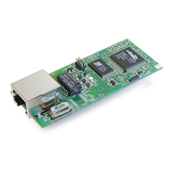
RCM3720 RabbitCore module.
•
RCM3720 Prototyping Board with RS-232 circuits installed.
•
Reach Technology SLCD controller board and color TFT touchscreen with screw-terminal power
•
connector and assembled serial cable interface.
Two AC adapters: 24 V DC (500 mA) with bare leads and 12 V DC, 1 A with 3-pin connector.
•
(AC adapters are included only with Application Kits
sold for the North American market).
Programming cable with level-matching circuitry.
•
DE9 to 10-pin serial adapter cable.
•
4 standoffs.
•
Getting Started instructions.
•
Rabbit 3000 Processor Easy Reference poster.
•
Registration card.
•
Getting Started
Installing Dynamic C
Insert the Dynamic C CD from the Applica-
tion Kit in your PC's CD-ROM drive. If the
installation does not auto-start, run the
setup.exe program in the root directory
of the Dynamic C CD. Install the software
from the Dynamic C supplemental CD after
you install Dynamic C
Z-World, Rabbit, and Dynamic C are registered trademarks of their
respective holders.
®
®
A Digi International
Company.
®
Advertisement
Table of Contents

Related Manuals for Rabbit RCM3720


Summary of Contents for Rabbit RCM3720
- Page 1 Dynamic C CD. Install the software Rabbit 3000 Processor Easy Reference poster. • from the Dynamic C supplemental CD after Registration card. you install Dynamic C • Z-World, Rabbit, and Dynamic C are registered trademarks of their respective holders.
- Page 2 COM port when you install Dynamic C or when you run it. Connect the 10-pin connector of the programming cable labeled PROG to header J2 on the RCM3720 as shown in Figure 2. Be sure to orient the marked (usually red) edge of the cable towards pin 1 of header J2.
- Page 3 Plug in the AC adapter. The power LED beside the RESET button on the Prototyping Board should light up. The RCM3720 and the Prototyping Board are now ready to be used. The RESET button is provided on the Prototyping Board to allow a hardware reset without disconnecting power.
- Page 4 J3 on the Prototyping Board to the serial cable interface as shown in Figure 2 to establish a serial connection with the RCM3720. Reconnect the programming cable to the PC COM port if you had to dis- connect it in order to use the PC COM port for the serial connection to the Reach Technology display in the above steps.
Need help?
Do you have a question about the RCM3720 and is the answer not in the manual?
Questions and answers