Table of Contents
Advertisement
Quick Links
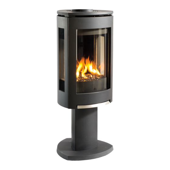
Jøtul GF 370 DV II IPI
Direct Vent Gas Stove
Pilot on Demand Ignition
Installation and
Operation Instructions
Certified to ANSI Z21.88-2019 • CSA 2.33-2019 and
CAN/CGA 2.17-M-17.
INSTALLER: Leave this manual with the appliance.
CONSUMER: Retain this manual for future reference.
WARNING: If the information in these
instructions is not followed exactly, a fire or
explosion may result causing property damage,
personal injury or loss of life.
– Do not store or use gasoline or other
flammable vapors and liquids in the
vicinity of this or any other appliance.
– WHAT TO DO IF YOU SMELL GAS
• Do not try to light any appliance.
• Do not touch any electrical switch; do
not use any phone in your building.
• Immediately call your gas supplier
from a neighbor's phone. Follow the gas
supplier's instructions.
• If you cannot reach your gas supplier,
call the fire department.
– Installation and service must be
performed by a qualified installer, service
agency or the gas supplier.
– In the Commonwealth of Massachusetts,
a carbon monoxide (CO) detector shall
be installed in the same room as the
appliance.
This appliance may be installed in an aftermarket,
permanently located, manufactured home or mobile
home, where not prohibited by local codes.
This appliance is only for use with the types of gas
indicated on the rating plate. A conversion kit is
supplied with the appliance.
DANGER
!
A barrier designed to reduce the burn hazard
from the glass viewing area is provided with this
appliance and shall be installed for the protection
of children and other at-risk individuals.
HOT GLASS WILL
CAUSE BURNS
.
DO NOT TOUCH GLASS
UNTIL COOLED.
NEVER ALLOW CHILDREN
TO TOUCH GLASS.
Advertisement
Table of Contents

Related Manuals for Jøtul GF 370 DV II IPI


Summary of Contents for Jøtul GF 370 DV II IPI
- Page 1 – Installation and service must be performed by a qualified installer, service agency or the gas supplier. Jøtul GF 370 DV II IPI – In the Commonwealth of Massachusetts, a carbon monoxide (CO) detector shall Direct Vent Gas Stove...
-
Page 2: Installation & Service Tools
139647_29 GF 370 DV II IPI 10/23 THIS OWNER’S MANUAL PROVIDES INFORMATION TO Installation Requirements for the ENSURE SAFE INSTALLATION AND EFFICIENT, DEPENDABLE Commonwealth of Massachusetts OPERATION OF YOUR FIREPLACE INSERT. PLEASE READ THESE INSTRUCTIONS IN THEIR ENTIRETY AND MAKE THEM... -
Page 3: Table Of Contents
Specifications ..........4 any evidence of damage to your dealer. General Information ........5 2. Confirm stove contents. Safety Information ........6 The Jøtul GF 370 DV II IPI includes the following loose items shipped in the Miscellaneous Hardware Installation bag; Hearth Requirements ......7 •... -
Page 4: Specifications
Fuel Conversion Kit, Propane - 33% TD ....#156800 Middleton, Wisconsin. Fuel Conversion Kit, Natural Gas - 33% TD..#156801 In addition, the Jøtul GF 370 DV II IPI has been High Altitude Adjustment Kit, NG .......#156822 tested and listed as a direct vent gas fireplace heater and listed to ANSI Z21.88-2019 •... -
Page 5: General Information
139647_29 GF 370 DV II IPI 10/23 General Information 5. Do not operate this fireplace if any part of it has been under water.. THIS HEATER MUST BE INSTALLED AND Immediately call a qualified service technician to MAINTAINED BY A QUALIFIED SERVICE AGENCY. -
Page 6: Safety Information
139647_29 GF 370 DV II IPI 10/23 Safety Information Due to the high operating temperatures this WARNING! appliance should be located out of traffic and away from furniture and draperies. Maintain Shock Hazard. Can cause severe injury or death. -
Page 7: Installation
7” 7” Hearth Requirements Figure 4. Alcove and Wall Clearances. The Jøtul GF 370 DV II IPI has been approved for ALCOVE SPECIFICATIONS: installation directly on combustible floor materials. Maximum Alcove Depth: 21 3/4” (55.2 cm) -
Page 8: Approved Vent Manufacturers
INSTRUCTIONS PROVIDED FOR THE INITIAL system design. INSTALLATION. Approved Vent Manufacturers The Jøtul GF 370 DV II IPI stove is approved for installation with direct vent chimney components supplied by the following manufacturers: M&G DuraVent, Inc. (Direct Vent Pro Series) P.O. -
Page 9: Masonry Chimney Conversion
139647_29 GF 370 DV II IPI 10/23 Horizontal Overhang Vertical Venting and Termination 18”. 18”. min. min. The Jøtul GF 370 DV II IPI can be vertically vented Lowest Discharge through a roof or ceiling. Follow these guidelines Opening Termination 18” min. -
Page 10: Horizontal Termination
139647_29 GF 370 DV II IPI 10/23 Horizontal Termination Figure 9. Minimum vent Minimum vertical rise from the vent collar is a 24” pipe sections required for horizontal termination: section vent pipe. See fig. 9. Minimum horizontal run A = 12” with NG is 12”... -
Page 11: Vent Termination Clearances
139647_29 GF 370 DV II IPI 10/23 Horizontal Termination Clearance 2 1/2” 12 ” 64 mm 3” 76 mm Figure 13. Termination Clearance to overhangs. Vent Terminal Air Supply Terminals Prohibited in this Area Figure 12. Vent Terminal Clearances - ANSI Z21.88-2019, CSA 2.33-2019, and NFPA 54 / ANSI Z223.1 National Fuel Gas Code. -
Page 12: Vent Restriction Adjustments
139647_29 GF 370 DV II IPI 10/23 Vent Restriction Adjustments The Jøtul GF 370 DV II IPI features adjustment controls Exhaust Restrictor Adjustment for both intake air and exhaust to accommodate a variety 1. Remove the Trim Rings from the Top Plate. -
Page 13: Vent Termination Diagram
139647_29 GF 370 DV II IPI 10/23 35 Ft. A maximum of two 90° (10.67 m) or four 45° elbows may be used. Whenever ZONE ZONE possible, use 45° elbows instead of 90° elbows as these offer less restriction to the 30 Ft. -
Page 14: Stove Assembly
139647_29 GF 370 DV II IPI 10/23 Stove Assembly 1. Glass Frame Removal To access the firebox, use the 4 mm hex key to remove the four socket head screws that attach the glass frame to the firebox. See fig. 18. -
Page 15: Gas Pressure
139647_29 GF 370 DV II IPI 10/23 3/8” NPT x 3/8” Flare Fitting 1/2” x 3/8” Flare Inlet Pressure Shut-off Valve Natural Gas: 5.0 WC (1.24 kPa) 7.0 WC (1.74 kPa) Propane: 12.0 WC (2.99 kPa) 14.0 WC (3.48 kPa) 3/8”... -
Page 16: Fuel Conversion
• Label B - apply to the rating plate in the space indi- cated on the plate. • Small valve label - apply to valve body The GF 370 DV II IPI gas stove is shipped from the factory • Conversion instructions equipped to burn Natural gas. Propane fuel conversion... - Page 17 139647_29 GF 370 DV II IPI 10/23 Figure 23. Fuel conversion components and pilot assembly detail. Flame Sensor Pilot Injector Ignitor Flame Sensor Primary Air Shutter Injector Regulator Diaphragm IFC Reset Button Regulator Use new Torx screws Tower supplied • Replace the pilot body, ensuring that the hood is screws securely.
-
Page 18: High Altitude Adjustment
139647_29 GF 370 DV II IPI 10/23 6. High Altitude Adjustment 7. Firebox Panel Installation The decreased atmospheric pressure of higher altitudes Skamol Panels and optional affects heat value of gaseous fuels. Most gas suppli- Reflective Glass Kit 156817 ers derate the gas intended for use at elevations above 2000 feet. -
Page 19: River Rock Installation
139647_29 GF 370 DV II IPI 10/23 8. Install Burner Media River Rocks CAUTION: THE ROCKS ARE FRAGILE! SUPPORT THE ASSEMBLY FROM THE BOTTOM AND HANDLE CARE- FULLY! 1. Engage the River Rock bed with the two center burner pins as shown in fig. 27. Either side of the rocks may face outward as desired. -
Page 20: Log Set Installation
139647_29 GF 370 DV II IPI 10/23 Tumbled Stones Install the stones according to the instructions supplied with that kit. Install the Log Set The three-piece log set includes a bag of ember stones that simulate glowing coals when the burner is operat- ing. -
Page 21: Outer Decorative Glass Panels
139647_29 GF 370 DV II IPI 10/23 Replace the Glass Frame Continued. 1. Connect the power extension cord to the interior power cord and to a 120V electrical outlet. 2. PURGING THE GAS LINE: Open the gas supply valve. 3) Replace the socket head screws into glass frame When lighting the appliance for the first time it will finger tight. - Page 22 139647_29 GF 370 DV II IPI 10/23 Flame Appearance / Air Shutter Adjustment WARNING: AIR SHUTTER ADJUSTMENTS SHOULD ONLY BE PERFORMED BY A QUALIFIED, PROFESSIONAL SERVICE TECHNICIAN. Locate the Primary Air Shutter control under the firebox floor above the gas valve. See fig. 37. The shutter is set at the midpoint of its adjustment range at the factory.
-
Page 23: Flame Picture Adjustment
139647_29 GF 370 DV II IPI 10/23 fire intensity. Conversely, as room temperature cools, Proflame 2 the valve gradually increases flame intensity. The overall result is more comfortable, even heating that minimizes Remote Control temperature peaks and valleys. Pilot Assembly Features Overview The pilot contains a pilot hood, igniter, and a flame sensor. -
Page 24: Operation System Overview
139647_29 GF 370 DV II IPI 10/23 Control Functions Initializing the System 1. Grasp the bottom of the Front Panel and swing it open to Pilot Mode the left. Switch the Burner to OFF. Set the stove switch to CPI mode for Proflame 2 2. - Page 25 139647_29 GF 370 DV II IPI 10/23 Remote Transmitter Controls, cont’d. Temperature Indication Display W ith the transmitter in the OFF position, press the Thermostat Key and the Mode Key at the same time. The display screen will show the current room temper- ature cycling between Farenheit and Celsius indica- Figure 42.
- Page 26 139647_29 GF 370 DV II IPI 10/23 SMART Thermostat Function This function adjusts the flame intensity according to the difference in the Set Point temperature and the actual room temperature. As the room temperature gets closer to the Set Point, the Smart Function will modulate flame intensity down.
-
Page 27: Maintenance
139647_29 GF 370 DV II IPI 10/23 Maintenance This appliance and its venting system should be NOTE: INSPECT THE GLASS SURFACE FOR inspected before use and at least annually by a SCRATCHES AS THESE CAN WEAKEN THE PANEL qualified service technician. -
Page 28: Battery Replacement
139647_29 GF 370 DV II IPI 10/23 Initializing the Remote Control Figure 59. Each time you replace the batteries, you will need to 156833 initialize communication between the Receiver and the Front Glass Transmitter. Replacement 1. Place the slider switch in the REMOTE position. -
Page 29: Wiring Diagram
INADÉQUAT ET DANGEREUX. Optional SIT Proflame 2 IFC Variable Lamp 120VAC Power Optional Variable Speed Blower Figure 61. GF 370 DV II IPI with Proflame 2 Premium Remote Control Accessories Figure 62. Wiring Diagram - GF 370 DV II IPI Fan... -
Page 30: Appendix
139647_29 GF 370 DV II IPI 10/23 Appendix 1. Top Plate Shims 1. Remove the Top Plate. Linen Enamel Stoves: Locate the three shims shipped separately within the firebox and install 2. Remove the three shims highlighted in the these in the same locations as those previously illustration below. -
Page 31: Mobile Home Installation
139647_29 GF 370 DV II IPI 10/23 3. Mobile Home Installation The Jøtul GF 370 DV II IPI can be installed for use in a mobile home in the U.S. and Canada provided: 1. The stove must be secured to the floor of the mo- bile home. -
Page 32: Beachfire Logset Installation
139647_29 GF 370 DV II IPI 10/23 4. Beachfire Logset LOG IDENTIFICATION 1. Log Retainer 22664192 4. Engage the holes in the bottom of Rear Log 2. Left Rear Log 226843 (#2) with the two steel pins (B) at the left rear corner of the burner plate. - Page 33 139647_29 GF 370 DV II IPI 10/23 Replace the Glass Frame NEVER USE A POWER TOOL TO TIGHTEN GLASS FRAME HARDWARE. Use the 4 mm hex key provided to secure screws. Wear clean cut resistant gloves when handling theglass and glass frame.
-
Page 34: Illustrated Replacement Parts
139647_29 GF 370 DV II IPI 10/23 lllustrated Part Breakdown Figure 66. Firebox Part Identification. No. Part Number Description 222982 Restrictor Plate, GF 370 9911 Bolt, Hex Cap, M6x45, DIN 933, Class 8.8, No. Part Number Description 22298392 Simpson DV II Starter Collar, GF 370, MB 9962 Bolt, Hex Cap M6x10 DIN 933 8.8 Ser Flange Blk... - Page 35 139647_29 GF 370 DV II IPI 10/23 Figure 67. External parts identification No. Part Number Description Part Number Description 117874 Bolt, Hex Hd M8 x 16 Ser Flange, Blk 223220 Plate, Centering, GF 370 99115 Bolt, Hex Hd M8 x 12 Ser Flange, Blk...
- Page 36 139647_29 GF 370 DV II IPI 10/23 Figure 68. GF 370 DVII IPI Spud assembly parts identification - For stoves with serial numbers after 10000.
- Page 37 139647_29 GF 370 DV II IPI 10/23 Part Number Description Use only genuine Jøtul Replacement Parts available from your local Authorized Jøtul 118262 Screw, #8 X 1.75” SMS Dealer or by contacting: 223204 Pilot Air Deflector Jøtul North America 158233 Pilot Assembly, NG, Flat Brkt, SS Body, 12”...
-
Page 38: Warranty Statement
139647_29 GF 370 DV II IPI 10/23 Jøtul GF 370 DV II IPI Limited Warranty This warranty policy applies to gas products or ship the component to an authorized Jøtul, Scan, or Atra dealer and arrange for pickup or delivery of the component after repairs have been identified by Jøtul, Scan, and Atra trade names, as set... - Page 39 139647_29 GF 370 DV II IPI 10/23 FIREPLACES. Some states do not allow the exclusion or limitation of incidental or consequential damages, or limitations on the length of implied warranties. Therefore, the above exclusions or limitations may not apply to you. This warranty gives you specific legal rights, and you may have other rights, which vary from state to state.
- Page 40 Please record the serial number in the space below. You may also wish to attach your purchase receipt to this page for future reference. MODEL NAME: Jøtul GF 370 DV II IPI Gas Stove SERIAL NUMBER:_______________________________ PURCHASE DATE: ____________________________...
-
Page 41: Lighting Instructions
139647_29 GF 370 DV II IPI 10/23 LIGHTING INSTRUCTIONS FOR YOUR SAFETY, READ BEFORE LIGHTING. WARNING: IF YOU DO NOT FOLLOW THESE INSTRUCTIONS EXACTLY, A FIRE OR EXPLOSION MAY RESULT CAUSING PROPERTY DAMAGE, PERSONAL INJURY, OR LOSS OF LIFE. A. This appliance is equipped with an ignition device which automatically lights the pilot. - Page 42 139647_29 GF 370 DV II IPI 10/23 This appliance must be installed in conformance with local and national building regulations. Before beginning the installation, it is important that the these instructions be carefully read and understood. Jøtul maintains a policy of continual product development. Consequently, products may differ in specification, color or type of accessories from those illustrated or described in various publications.
Need help?
Do you have a question about the GF 370 DV II IPI and is the answer not in the manual?
Questions and answers