Jøtul GF 3 CF 2 Installation And Operation Instructions Manual
Conventional flue gas stove
Hide thumbs
Also See for GF 3 CF 2:
- Installation and operating instructions manual (12 pages) ,
- Installation and operating instructions manual (60 pages)
Table of Contents
Advertisement
Installation and
Operation Instructions
WARNING: If the information in
these instructions is not followed
exactly, a fire or explosion may
result causing property damage,
personal injury or death.
– Do not store or use gasoline or
other flammable vapors and
liquids in the vicinity of this or any
other appliance.
– WHAT TO DO IF YOU SMELL GAS
• Do not try to light any appliance.
• Do not touch any electrical
switch; do not use any phone in
your building.
• Immediately call your gas supplier
from a neighbor's phone.
Follow the gas supplier's
instruction.
• If you cannot reach your gas
supplier, call the fire department.
– Installation and service must be
performed by a qualified installer,
service agency or the gas supplier.
1
Advertisement
Table of Contents

Related Manuals for Jøtul GF 3 CF 2


Summary of Contents for Jøtul GF 3 CF 2
-
Page 1: Operation Instructions
Installation and Operation Instructions WARNING: If the information in these instructions is not followed exactly, a fire or explosion may result causing property damage, personal injury or death. – Do not store or use gasoline or other flammable vapors and liquids in the vicinity of this or any other appliance. - Page 2 Jøtul appliance. Save this user manual and make sure it is available for service personnel. Annual service - year 9 Sign.: Company: Date: Model Name: Jøtul GF 3 CF 2 Service details: Serial No.: Purchase Date: Annual service - year 10 Sign.:...
-
Page 3: Table Of Contents
Table of Contents THIS OWNER’S MANUAL PROVIDES INFORMATION TO ENSURE SAFE INSTALLATION AND EFFICIENT, DEPENDABLE OPERATION OF YOUR STOVE. PLEASE READ THESE INSTRUCTIONS IN THEIR ENTIRETY AND MAKE 1. Technical Information ......4 THEM AVAILABLE TO ANYONE USING OR SERVICING THIS GAS STOVE. 2. -
Page 4: Technical Information
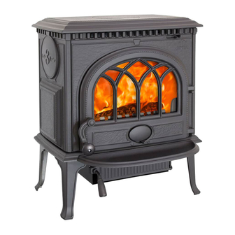
Jøtul GF 3 CF 2 Technical Information 292 mm Material: Cast iron/steel Finish: Blue Black enamel or Matte Black paint 114 mm Flue outlet: Top or Rear Vent system: BV-standard system 420 mm Weight: Approx. 71 kg (product) PIN: 0063BS5908 Product dimensions: See fig. -
Page 5: General Information
General Information Safety Precautions This product has been approved to the European This appliance must be installed in accordance with the Standard EN 613:2000 and is in accordance with EC rules in force. Consult instructions before installation Gas Appliances Directive (90/396/EEC). and use of this appliance. -
Page 6: Installer Information
Installer Information The Flue must be checked for soundness and swept prior to installation it should only be used if clean and in good 435 mm order. Before installation, check that the local distribution conditions, nature of the gas and pressure, and the adjustment of the appliance are compatible. - Page 7 Vent Height off Draft Hood: Min. 2.15 m (7’) 520 mm Max. 3.7 m (35’) 635 mm (25”) Draft Hood 550 mm (21 5/8”) Figure 7. Clearance to a combustible shelf. Figure 8. Vent height requirements. Flue System Installation Closure Plate Installation Flue outlet (spigot) dimensions: It is permissible to install this appliance using a closure Internally = 128 mm...
- Page 8 Assembly Prior To Installation All brick flues or any flue previously used with solid fuel or gas appliances must be left with the appropri- The product is delivered in 1 package. In the firebox ate debris collection volume below the flue spigot of you will find the propane fuel conversion kit, four the stove of 12 litres minimum 12 litres minimum...
- Page 9 Logset Installation PN 220729 Brick Kit Note: Brick Kit Note: Brick Kit Note: Brick Kit Note: Brick Kit Note: Install the optional Antique Brick Kit 155370 before installing the log set. See instructions supplied with that kit. The GF 3 CF2 log set must be installed before operating the burner.
-
Page 10: Gas Installation
Gas Installation Commissioning Gas installation must only be performed by qualified Testing the Flue System personnel. It is important to adhere to national and local Once the appliance is fitted, gas leak and pressure tested, regulations that apply. In the UK these include BS5440 Pt and the flue system complete, the flue must be checked 1&2 and BS5871 in Ireland. -
Page 11: Annual Service
Regulating the Pilot Flame Figure 17. The pilot flame should have three flames as shown in fig. Proper pilot flame / 17. The two thermo-element sticks should be surrounded by carry-over port two of the flames as shown in fig. 18. alignment. -
Page 12: User Information
User Information Operating Instructions General Assembly, installation, maintenance and gas conversion (if Lighting required) must be performed by a qualified person in accordance with the instructions for assembly, Installation Note! Odors when using the stove: and use enclosed with the product. The installation may When used for the first time, the appliance may emit only be operated after it has been inspected by a qualified an irritating gas that may smell a little. -
Page 13: External Maintenance
Figure 21. Valve Controls. Figure 22. Burner Controls. Adjusting the Heat Setting 4. Push in the gas control knob (B) as far as possible and hold it in. Simultaneously, push in the ignition knob (A) Heat and flame size can be adjusted by turning the until the spark ignites the pilot flame located to the regulator knob (C) marked “HI, LOW”, which is located next right rear corner of the burner.. -
Page 14: Troubleshooting
Troubleshooting When No Spark is Generated at the Pilot Head It is uncommon for the Piezo spark ignitor (fig 23-A) to fail, unless it has mechanical damage. If the spark is not conducted forward, it could be the result of a break in the electrical circuit leading up to the pilot head. - Page 15 When There is No Gas Flow Thermocouple (Fig.24) and Thermopile To The Pilot Head (Fig. 25) A thermocouple is in principle a thermal generator and This is the trouble-shooting procedure for the gas supply: consists of a copper wire (copper-nickel alloy) and an iron Check if all gas connections are sealed by using strong wire twisted together.
- Page 16 When There is No Gas Supply to the Burner. Figure 24. Thermocouple system This is the trouble-shooting procedure for the electrical check. components: 1. Make sure the control knob on the valve is set to “ON”. Check the position on the “ON/OFF/Thermostat” switch at the back of the appliance.
- Page 17 Burner Orifice Figure 26. Check main burner orifice for debris blockage. Burner pan is removed.
- Page 19 Jøtul GF 3 CF 2 Parts List Blue Black Blue Black Blue Black Ivory Ivory Ivory Brown Brown Brown Blue Blue Blue Blue Black Blue Black Ivory Ivory Brown Brown Blue Blue Cast Iron Parts Cast Iron Parts Cast Iron Parts...
- Page 20 This appliance must be installed in conformance with local and national building regulations. Before beginning the installation, it is important that the these instructions be carefully read and understood. Jøtul maintains a policy of continual product development. Consequently, products may differ in specification, color or type of accessories from those illustrated or described in various publications.
Need help?
Do you have a question about the GF 3 CF 2 and is the answer not in the manual?
Questions and answers