Table of Contents
Advertisement
Quick Links
Advertisement
Table of Contents

Related Manuals for optris CT XL 3M


Summary of Contents for optris CT XL 3M
- Page 1 Operator’s Manual ® optris CT XL Infrared thermometer...
- Page 2 Optris GmbH Ferdinand-Buisson-Str. 14 13127 Berlin Germany Tel.: +49 30 500 197-0 Fax: +49 30 500 197-10 E-mail: info@optris.global Internet: www.optris.global...
-
Page 3: Table Of Contents
Table of Contents Table of Contents Table of Contents ............................. 3 General Information ..........................7 Description ............................7 Warranty ............................8 Scope of Supply ..........................8 Maintenance ............................. 9 Model Overview ..........................9 Factory Default Settings ......................... 10 Technical Data ............................12 General Specifications ........................ - Page 4 Mechanical Installation .......................... 22 Accessories ............................24 Air Purge Collar ..........................24 Mounting Brackets .......................... 25 Rail Mount Adapter for Electronic box .................... 26 Electrical Installation ..........................27 Cable Connections ......................... 27 Ground Connection [3M models] ....................30 Outputs and Inputs ..........................31 Analog Outputs ..........................
- Page 5 Table of Contents Operating ..............................35 Sensor Setup ..........................35 Error messages ..........................41 Software CompactConnect ........................42 Installation ............................42 Communication Settings ........................ 43 Basics of Infrared Thermometry......................45 Emissivity ............................... 46 10.1 Definition............................46 10.2 Determination of unknown Emissivity .................... 46 10.3 Characteristic Emissivity ........................
- Page 6 Appendix D – Declaration of Conformity ..................... 52...
-
Page 7: General Information
1.1 Description Thank you for choosing the optris® CT XL infrared thermometer. The sensors of the optris CT XL series are noncontact infrared temperature sensors. They calculate the surface temperature based on the emitted infrared energy of objects [►9 Basics of Infrared Thermometry]. -
Page 8: Warranty
1.2 Warranty Each single product passes through a quality process. Nevertheless, if failures occur please contact the customer service at once. The warranty period covers 24 months starting on the delivery date. After the warranty is expired the manufacturer guarantees additional 6 months warranty for all repaired or substituted product components. -
Page 9: Maintenance
The sensors of the CT XL series are available in the following basic versions: Model Model codes Measurement Spectral response Typical applications range 100 to 600 °C 3MH1 150 to 1000 °C CT XL 3M 2,3 µm metallic surfaces 3MH2 200 to 1500 °C 3MH3 250 to 1800 °C... -
Page 10: Factory Default Settings
1.6 Factory Default Settings The unit has the following presetting at time of delivery: Signal output object temperature 0-5 V Emissivity 1,000 Transmissivity 1,000 Averaging (AVG) inactive Smart Averaging active Peak hold inactive Valley hold inactive 3MH1 3MH2 3MH3 Lower limit temperature range [°C] Upper limit temperature range [°C] 1000 1500... - Page 11 General Information Baud rate [kBaud] Smart Averaging means a dynamic average adaptation at high signal edges. [Activation via software only]. ►Appendix C – Smart Averaging...
-
Page 12: Technical Data
2 Technical Data 2.1 General Specifications Sensing head Electronic box Environmental rating IP65 (NEMA-4) Ambient Temperature -20...85 °C -20...85 °C Storage temperature -40...85 °C Relative humidity 10...95 %, non condensing Material stainless steel die casting zinc Dimensions 112 mm x 32 mm, M30x1 89 mm x 70 mm x 30 mm Weight 120 g... -
Page 13: Electrical Specifications
Technical Data 2.2 Electrical Specifications Power Supply 8–36 VDC Current draw max. 100 mA Outputs/ analog Channel 1 selectable: 0/ 4–20 mA, 0–5/ 10 V, thermocouple (J or K) or alarm output (Signal source: object temperature) Alarm output Open collector output at Pin AL2 [24 V/ 50 mA] Output impedances max. -
Page 14: Measurement Specifications [3M Models]
2.3 Measurement Specifications [3M models] 3MH1 3MH2 3MH3 100…600 °C 150…1000 °C 200…1500 °C 250…1800 °C Temperature range (scalable) Spectral range 2,3 µm Optical resolution 100:1 300:1 2), 3), 4) System accuracy ±(0,3 % of reading +2 °C) 2), 4) Repeatability ±(0,1 % of reading +1 °C) Temperature resolution (NETD) -
Page 15: Optical Charts
The spot size refers to 90 % of the radiation energy. The distance is always measured from the front edge of the sensing head. As an alternative to the optical diagrams, the spot size calculator can also be used on the optris website http://www.optris.com/spot-size-calculator. - Page 16 Optics: SF D:S (focus distance) = 100:1 11mm@ 1100mm D:S (far field) = 38:1 Optics: CF1 D:S (focus distance) = 100:1 0,85mm@ 85mm D:S (far field) = 3:1...
- Page 17 Technical Data Optics: CF2 D:S (focus distance) = 100:1 1,5mm@ 150mm D:S (far field) = 7:1 Optics: CF3 D:S (focus distance) = 100:1 2mm@ 200mm D:S (far field) = 9:1...
- Page 18 Optics: CF4 D:S (focus distance) = 100:1 4,5mm@ 450mm D:S (far field) = 19:1 Optics: FF D:S (focus distance) = 100:1 36mm@ 3600mm...
- Page 19 Technical Data 3MH1 - 3MH3 Optics: FF D:S (focus distance) = 300:1 12mm@ 3600mm D:S (far field) = 115:1 3MH1 - 3MH3 Optics: SF D:S (focus distance) = 300:1 3,7mm@ 1100mm D:S (far field) = 48:1...
- Page 20 3MH1 - 3MH3 Optics: CF2 D:S (focus distance) = 300:1 0,5mm@ 150mm D:S (far field) = 7,5:1 3MH1 - 3MH3 Optics: CF3 D:S (focus distance) = 300:1 0,7mm@ 200mm D:S (far field) = 10:1...
- Page 21 Technical Data 3MH1 - 3MH3 Optics: CF4 D:S (focus distance) = 300:1 1,5mm@ 450mm D:S (far field) = 22:1...
-
Page 22: Mechanical Installation
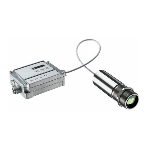
3 Mechanical Installation The CT XL sensing heads are equipped with a metrical M30x1-thread and can be installed either directly via the sensor thread or with help of the hex nut (included in scope of supply) to the mounting bracket available. CT XL –... - Page 23 Mechanical Installation CT XL Electronic box...
-
Page 24: Accessories
4 Accessories 4.1 Air Purge Collar The lens must be kept clean at all times from dust, smoke, fumes and other contaminants in order to avoid reading errors. These effects can be reduced by using an air purge collar. Make sure to use oil-free, technically clean air, only. -
Page 25: Mounting Brackets
Accessories 4.2 Mounting Brackets Mounting bracket, adjustable Mounting bracket, adjustable in in one axis [ACCTXLFB] two axes [ACCTXLAB] With the help of this bracket the sensing head can be adjusted in two axes. -
Page 26: Rail Mount Adapter For Electronic Box
4.3 Rail Mount Adapter for Electronic box With the rail mount adapter the CT XL electronics can be mounted easily on a DIN rail (TS35) according EN50022. Rail Mount Adapter [ACCTRAIL] ► All accessories can be ordered according to the referred part numbers in brackets [ ]. -
Page 27: Electrical Installation
Electrical Installation 5 Electrical Installation 5.1 Cable Connections For the electrical installation of the CT XL please open at first the cover of the electronic box (4 screws). Below the display are the screw terminals for the cable connection. Designation [model 3M] +8..36 VDC Power supply Ground (0 V) of power supply... - Page 28 Power supply Please use a power supply unit with an output voltage of 8–36 VDC which can supply 100 mA. The ripple should be max. 200 mV. Please do never connect a supply voltage to the analog outputs as this will destroy the output! The CT XL is not a 2-wire sensor!
- Page 29 Electrical Installation Cable Assembling The cable gland M12x1,5 allows the use of cables with a diameter of 3 to 5 mm. Remove the isolation from the cable (40 mm power supply, 50 mm signal outputs, 60 mm functional inputs). Cut the shield down to approximately 5 mm and spread the strands out. Extract about 4 mm of the wire isolation and tin the wire ends.
-
Page 30: Ground Connection [3M Models]
5.2 Ground Connection [3M models] At the bottom side of the mainboard PCB you will find a connector (jumper) which has been placed from factory side as shown in the picture [bottom and middle pin connected]. In this position the ground connections (GND power supply/ outputs) are connected with the ground of the electronics housing. -
Page 31: Outputs And Inputs
Outputs and Inputs 6 Outputs and Inputs 6.1 Analog Outputs CAUTION: Please do never connect a supply voltage to the analog outputs as this will destroy the output. The CT XL has two analog output channels. The CT XL is not a 2-wire sensor! Output channel 1 This output is used for the object temperature. -
Page 32: Digital Interfaces
6.2 Digital Interfaces CT XL sensors can be optionally equipped with an USB-, RS232-, RS485-, CAN Bus-, Profibus DP- or Ethernet- interface. If you want to install an interface, plug the interface board into the place provided, which is located beside the display. In the correct position the holes of the interface match with the thread holes of the electronic box. -
Page 33: Functional Inputs
Outputs and Inputs The switching thresholds are in accordance with the values for alarm 1 and 2 [►6.5 Alarms]. The alarm values are set according to the ►1.6 Factory Default Settings. To make advanced settings (change of low- and high alarm) a digital interface (USB, RS232) and the software is needed. -
Page 34: Alarms
6.5 Alarms All alarms (alarm 1, alarm 2, output channel 1 if used as The CT XL has the following Alarm features: alarm output) have a fixed hysteresis of 2 K. Output channel 1 To activate the according output channel has to be switched into digital mode. For this purpose the software CompactConnect is required. -
Page 35: Operating
Operating 7 Operating After power up the unit the sensor starts an initializing routine for some seconds. During this time the display will show INIT. After this procedure the object temperature is shown in the display. The display backlight color changes according to the alarm settings [►6.5 Alarms]. 7.1 Sensor Setup The programming keys Mode, Up and Down enable the user to set the sensor on-site. - Page 36 Display Mode [Sample] Adjustment Range 142.3C Object temperature (after signal processing) [142,3 °C] fixed 127CH Head temperature [127 °C] fixed 25CB Box temperature [25 °C] fixed 142CA Current object temperature [142 °C] fixed 0-20 = 0–20 mA/ 4-20 = 4–20 mA/ MV5 = 0–5 V/ Signal output channel 1 [0-5 V] MV10 = 0-10 V/...
- Page 37 Operating MV5 ´ Selection of the Output signal. By pressing Up or Down the different output signals can be selected [► Outputs and Inputs]. E0.970 Setup of Emissivity. Pressing Up increases the value, Down decreases the value (also valid for all further functions). The emissivity is a material constant factor to describe the ability of the body to emit infrared energy [►10 Emissivity].
- Page 38 V---- Setup of Valley hold. In this mode the sensor waits for ascending signals. The definition of the algorithm is according to the peak hold algorithm (inverted). If the value is set to 0.0 the display will show --- (function deactivated). Signal graph with P---- ▬...
- Page 39 Operating Setup of the Lower limit of temperature range. The minimum difference between lower and upper limit is 20 K. If you set the lower limit to a value ≥ upper limit the upper limit will be adjusted to [lower limit + 20 K] automatically. n 500.0 Setup of the Upper limit of the temperature range.
- Page 40 To compensate this impact, this function allows the setup of a fixed value which represents the ambient radiation. If XHEAD is shown the ambient temperature value will be taken from the head-internal probe. To return to XHEAD please press Up and Down together. Especially if there is a big difference between the ambient temperature at the object and the head temperature the use of Ambient temperature compensation is recommended.
-
Page 41: Error Messages
Operating 7.2 Error messages The display of the sensor can show the following error messages: 3M models: 1. Digit: No error Head temperature probe short circuit to GND Box temperature too low Box temperature too high Box temperature probe disconnected Box temperature probe short circuit to GND 2. -
Page 42: Software Compactconnect
8 Software CompactConnect 8.1 Installation Minimum system requirements: Windows 7, 8, 10 Insert the installation CD into the according drive on USB interface your computer. If the autorun option is activated the Hard disc with at least 30 MByte free space installation wizard will start automatically. -
Page 43: Communication Settings
Software CompactConnect 8.2 Communication Settings Serial Interface Baud rate: 9,6...115,2 kBaud (adjustable on the unit or via software) Data bits: Parity: none Stop bits: Flow control: Protocol All sensors of the CT XL series are using a binary protocol. Alternatively they can be switched to an ASCII protocol. - Page 44 Saving of parameter settings After power on of the CT XL sensor the flash mode is active. It means, changed parameter settings will be saved in the CT XL-internal Flash-EEPROM and will be kept also after the sensor is switched off. In case settings should be changed quite often or continuously the flash mode can be switched off by using the following command: Decimal:...
-
Page 45: Basics Of Infrared Thermometry
Basics of Infrared Thermometry 9 Basics of Infrared Thermometry Depending on the temperature each object emits a certain amount of infrared radiation. A change in the temperature of the object is accompanied by a change in the intensity of the radiation. For the measurement of “thermal radiation”... -
Page 46: Emissivity
10 Emissivity 10.1 Definition The intensity of infrared radiation, which is emitted by each body, depends on the temperature as well as on the radiation features of the surface material of the measuring object. The emissivity (ε – Epsilon) is used as a material constant factor to describe the ability of the body to emit infrared energy. -
Page 47: Characteristic Emissivity
Emissivity and take the temperature of the sticker. Afterwards, determine the temperature of the adjacent area on the measuring object and adjust the emissivity according to the value of the temperature of the sticker. ► Cove a part of the surface of the measuring object with a black, flat paint with an emissivity of 0,98. Adjust the emissivity of your infrared thermometer to 0,98 and take the temperature of the colored surface. -
Page 48: Appendix A - Emissivity Table Metals
Appendix A – Emissivity Table Metals Material typical Emissivity Spectral response 1,0 µm 1,6 µm 5,1 µm 8-14 µm Aluminium non oxidized 0,1-0,2 0,02-0,2 0,02-0,2 0,02-0,1 polished 0,1-0,2 0,02-0,1 0,02-0,1 0,02-0,1 roughened 0,2-0,8 0,2-0,6 0,1-0,4 0,1-0,3 oxidized 0,2-0,4 0,2-0,4 Brass polished 0,35 0,01-0,05... - Page 49 Appendix A – Emissivity Table Metals Material typical Emissivity Spectral response 1,0 µm 1,6 µm 5,1 µm 8-14 µm Lead polished 0,35 0,05-0,2 0,05-0,2 0,05-0,1 roughened 0,65 oxidized 0,3-0,7 0,2-0,7 0,2-0,6 Magnesium 0,3-0,8 0,05-0,3 0,03-0,15 0,02-0,1 Mercury 0,05-0,15 0,05-0,15 0,05-0,15 Molybdenum non oxidized 0,25-0,35...
-
Page 50: Appendix B - Emissivity Table Non Metals
Appendix B – Emissivity Table Non Metals Material typical Emissivity Spectral response 1,0 µm 2,2 µm 5,1 µm 8-14 µm Asbestos 0,95 Asphalt 0,95 0,95 Basalt Carbon non oxidized 0,8-0,9 0,8-0,9 0,8-0,9 graphite 0,8-0,9 0,7-0,9 0,7-0,8 Carborundum 0,95 Ceramic 0,8-0,95 0,8-0,95 0,95 Concrete... -
Page 51: Appendix C - Smart Averaging
Appendix C – Smart Averaging Appendix C – Smart Averaging The average function is generally used to smoothen the output signal. With the adjustable parameter time this function can be optimal adjusted to the respective application. One disadvantage of the average function is that fast temperature peaks which are caused by dynamic events are subjected to the same averaging time. - Page 52 Appendix D – Declaration of Conformity...
Need help?
Do you have a question about the CT XL 3M and is the answer not in the manual?
Questions and answers