Ecom J2KN pro Operation Manual
Hide thumbs
Also See for J2KN pro:
- Operating instructions manual (58 pages) ,
- Operation manual (40 pages) ,
- Quick manual (12 pages)

Related Manuals for Ecom J2KN pro


Summary of Contents for Ecom J2KN pro
- Page 1 Operations Manual version 3.3.3 ECOM America Ltd, 1628 Oakbrook Drive, Gainesville, GA 30507 Toll free (877) 326-6411 Phone (770) 532-3280 Fax (770) 532-3620 ww w. eco mu s a. co m...
- Page 2 Page 2...
-
Page 3: Table Of Contents
Page(s) J2KN P ESIGN AND OW IT ORKS 1. Important Things to Remember 2. Instrument Design 2.1. J2KN Pro Base Unit 2.2. Remote Display Unit 2.3. Accessories 2.4. Consumables 3. Peltier Cooler 4. Gas Path Diagram 5. Power Supply 6. Radio Communication... -
Page 4: Important Things To Remember
1. Important Things to Remember The J2KN Pro meets the requirements of EPA CTM-030 and CTM-034 and ASTM D-6522 test- ing protocols for portable emission analyzers. In order to receive accurate measurements, please allow reading to stabilize for at least 2 minutes. -
Page 5: Instrument Design
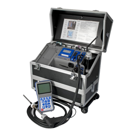
2. Instrument Design 2.1 J2KN Pro Base Unit Draft/Pressure connection Main gas Info display connection (see 13. Control) Thermocouple Draft/Pressure connection connection Data cable Ambient air connection (used by ECOM temperature personnel only) sensor Analogue ON / OFF inputs button... -
Page 6: Remote Display Unit
Escape Press to add custom text to printout (To print real-time results, simply press ON/OFF Data cable sockets (used by ECOM per- Note: All keypad sonnel only) buttons are used for input of numbers 0-9 and decimal point Page 6... -
Page 7: Accessories
2.3 Accessories Advanced DAS Compliance Calibration Gas Kit Testing Software w/ Bluetooth Part no. CALGASKIT1 Part no. PRT90205 Under Case 15ft Heated Sample Line Part no. RBR69825 (Pro Easy) Part no. PRT79525-15 Part no. RBR69829 (Pro IN) (Pictured on page 5) T-Gas Dummy Plug T-Air Sensor Stick Part no. -
Page 8: Consumables
2.4 Consumables PART PART # DESCRIPTION 10/PK - Particulate Particulate FILTER filter located on top of Filter (10/PK) 75316 water trap assembly 1 EACH - Standard 3/4" In-line Smoke in-line filter in clear Filter (1 EACH) 71185 plastic casing. 100/PK - Round smoke Soot Test Paper SOOT test filters for smoke... -
Page 9: Peltier Cooler
Monitoring Electrodes Inlet Water drain J2KN Pro must be plugged in for the Peltier cooler to operate. Exhaust gas with a temperature above dew point is intro- duced into a spiralling gas path with a coated metal surface of good thermal conductivity. The hot gas radiates its heat to... -
Page 10: Gas Path Diagram
4. Gas Path Diagram Response Time After inserting the probe into the sample gas, there is a short delay before correct measurement values are dis- played. This is necessary for the gas to pass through the sampling system and build up a stable electrochemical reac- tion at the sensors. -
Page 11: Power Supply
5. Power Supply The J2KN Pro base unit has an internal power supply, and it is recommended to always run the unit on AC power. For testing locations where an AC plug-in is not available, the instrument can be operated from 6-8 hours on battery power when fully charged. -
Page 12: Radio Communication
6. Radio Communication The J2KN Pro base unit communi- Unlock cates wirelessly to the remote display unit via radio transmisision. To unlock the remote control unit, press on the tab to unlock and release from the cradle on the base unit. -
Page 13: J2Kn Pro Start-Up
7. J2KN Pro Start-up Make sure the probe is in fresh air when you turn on the J2KN Pro. Gas analysis Radio Link Averaging Display contrast: Quality Indicator Lighten F1 Draft/Pressure Darken F2 Soot Test Automatic meas. Battery Charging Adjustments... -
Page 14: Emissions Measurement
8. Emissions Measurement 8.1 Gas Analysis Calibrate the sensors before each emission test for best results. After the 1-minute auto-zeroing phase, the instrument switches to Gas Analysis mode. The measurement values can be viewed on 3 display pages: a zoomed in 4-line display and 2 full 9-line displays. -
Page 15: Gas Analysis
8.1 Gas Analysis (continued) Core Stream Search 8.2 % To obtain the most accurate gas 431 ppm 126 ppm sample, the end of the probe should be 65 ppm positioned in the center of the exhaust stream or the “core stream” where the Gas analysis thermocouple is fully surrounded with 25.11.07... -
Page 16: Printing
8.2 Printing Wait for the measurement values to stabilize for at least 2 minutes before printing the results. Quick Print The easiest and quickest way to print is to press <F2> for quick print, which immediately prints the measurement values currently on the screen. -
Page 17: Soot Test
To turn probe heating on, go to Adjustments -> Internal -> Probe heating -> F1 J2KN Pro must be plugged in for the probe heating function to activate. Allow 3 minutes for the probe to heat up before soot test. -
Page 18: Data Logging Onto Memory Card
9. Data Logging onto Memory Card (2GB max) Initial Set-up 1. Insert memory card (32MB to 2GB) into the top-right of the handheld display 2. Go to Automatic Meas. -> Save to MM Card. This is the time interval that each data snapshot is recorded to the memory card (min. -
Page 19: Averaging Tests
10. Averaging Tests The Averaging function allows you to take a sample of emissions data and compute an average over time. 1. Go to Averaging -> Select Meas. Time Averaging Start measurement 2. Input total measuring time in minutes or Meas. -
Page 20: Draft/Pressure
11. Draft/Pressure A trend indication for the draft conditions in the exhaust channel is displayed in the Gas Analysis screen. Note that the pressure sensor tends to drift because of its sensitivity, and it is necessary to calibrate the sensor immediately before sam- pling to get an accurate measurement. -
Page 21: Adjustments
12. Adjustments (continued) parts per million mg/m3 milligrams per cubic meter mg/kWh (undiluted) milligrams per kilowatt-hours corrected to O2% mg/MJ (undiluted) milligrams per megajoules corrected to O2% ppm (undiluted) parts per million corrected to O2% mg/m3 (undiluted) milligrams per cubic meter corrected to O2% lbs/mmBTU (undiluted) pounds per million BTU corrected to O2% *Undiluted = concentration value corrected to reference O2%... -
Page 22: Internal
12.1 Internal Printout contrast (Go to Adjustments > Internal) Reload function Print contrast Key beep Choose print contrast from 0-9 Graphic menu Reload function Probe heating Choose remote unit battery recharging Quit with: settings (see 5. Power Supply) Power saving mode Key beep Language: English Press F1/F4 to turn key beep on/off... -
Page 23: Internal
Set the Pitot factor for flow rate calculation. If the flow rate calculation is not needed, set Pitot factor to 0. If you are using a standard ECOM probe, set this to 0.93. (For more information on the flow measurement option, see 17. Flow Measurement with Pitot Tube.) -
Page 24: Control
13. Control The electrochemical sensors change their output values over time based on frequency of use. The J2KN-Pro is pro- grammed to monitor the sensors and correct drifts. If the drifts and the correlated measurement errors increase, an er- ror message is displayed and it is time to change the sensor. The control menu displays the status of the sensors, batter- ies, radio quality, error count, number of times the J2KN-Pro has started up, and other analyzer information. -
Page 25: Maintenance Tips
14. Maintenance Tips Only use sensors, filters, and filter media provided by ECOM. Do not use desiccant! 14.1 Filters Particulate filter (water trap filter) Unscrew the cover of the water trap and check the particu- late filter for greyness. Change it once the filter has a dark- ness of 4-5 on the soot chart scale. -
Page 26: Filters
14.1 Filters (continued) Ventilation filter The ventilation filter should be changed if the filter has a darkness of 2-3 on the soot chart scale. Use a screwdriver to pry open the filter holder from the slots on each side. Change the filter cartridge and refasten the filter holder. -
Page 27: Sensors
14.3 Sensors (continued) The CO sensor is protected from exposure to high con- centrations by the automatic CO bypass pump. If the limit value of 4000 ppm is exceeded, a second pump switches on and purges the sensor with fresh air. 14.4 Printer Paper To change the printer paper, please follow these steps: 1. -
Page 28: How To Change Sensors
15. How to Change Sensors Improper installation voids warranty! Please mark connector when removing old sensor and insert new sensor into correct connector to prevent destruction of the sensor and main board. 15.1 How to Change O2 Sensor Step 1: Step 2: Use a T-10 The O2... -
Page 29: A5F Co Sensor
15.2 How to Change A5F CO Sensor Improper installation voids warranty! Please mark connector when removing old sensor and insert new sensor into correct connector to prevent destruction of the sensor and main board. Step 1: Step 2: Use T-10 torx The A5F CO wrench to sensor is in... -
Page 30: A5F Co Sensor
15.2 How to Change A5F CO Sensor (continued) Step 5: Step 6: Pop open the After the gray cap cap is using a small removed, screwdriver slide the sensor out Use the side of the of the hous- housing as ing as a shown here leverage... -
Page 31: Mem Co Sensor
15.3 How to Change MEM CO Sensor Step 1: Step 2: Use T-10 The MEM CO torx wrench sensor is to remove shown here screws from O2/CO cover plate Step 3: Step 4: Disconnect Remove 3 ribbon screws cable from shown here CO sensor using a... -
Page 32: No, No2, So2, & High Co Sensors
15.4 How to Change NO, NO2, SO2, and High CO Sensors Improper installation voids warranty! Please mark connector when removing old sensor and insert new sensor into correct connector to prevent destruction of the sensor and main board. Step 1: Step 2: Disconnect Set J2KN on its... - Page 33 15.4 How to Change NO, NO2, SO2, and High CO Sensors (continued) Step 5: Step 6: Use T-10 torx Remove wrench to cradle as remove screws shown here shown here (notice O2 sensor Remove O2/CO removed) cover plate Do not force Remove O2 cradle—it sensor by...
-
Page 34: No, No2, So2, & High Co Sensors
15.4 How to Change NO, NO2, SO2, and High CO Sensors (continued) Step 9: Place board onto new sensor Step 10: Insert new sensor, turn 45 degrees clockwise to lock into place, and replace ribbon cable Step 11: Repeat steps 7-10 for each sensor you would like to change Step 12: When done, replace cradle and reinstall O2 sensor by screwing clockwise until locked &... -
Page 35: How To Calibrate Sensors
16. How to Calibrate Sensors For best results, the calibration gas concentration should be as close to the expected levels of emissions as possible. Because each sensor is linear through a nominal range, one calibration gas concentration can be used for a reasonably wide range of emission levels. - Page 36 16. How to Calibrate Sensors (continued) Put analyzer in calibration mode: Select Control on main menu. Swipe calibration magnet over the silver Cal Magnet sticker, located at bottom left of keypad. The analyzer is now in calibration mode. Calibrate your analyzer: Connect calibration gas to analyzer using one of the following three set-ups: option) Measure flow of pump at point of cal gas input with...
-
Page 37: Flow Velocity Measurement (Option)
First, the Pitot factor must be entered in the Adjustments menu to get the correct flow rate calculation. Input 0.93 for the Pitot factor if you are using a standard ECOM probe. To do this, go to: Adjustments -> Internal -> Pitot factor... -
Page 38: Frequently Asked Questions
18. Frequently Asked Questions In the Control screen, all important instru- Where do I find important in- ment information is shown (e.g. battery volt- strument information? age, sensor values, serial number, next ser- vice date, operation hours, etc.). The life span depends on the operating hours How long is the life span of the and the instrument equipment. -
Page 39: Frequently Asked Questions
Hint: If you have several J2KN-Pro analyzers, you can find the source of an error by exchanging the accessories (probe, hose, temperature sensor, etc.) If you have any further questions, do not hesitate to contact the ECOM America Service Department at 770-532-3280 Page 39... -
Page 40: Technical Data
19. Technical Data Parameter Range Principle 0 ... 21.0 vol-% Electrochemistry 0 ... 4000 ppm Electrochemistry CO% (Option) 4000 ... 63000 ppm Electrochemistry 0 ... 5000 ppm Electrochemistry 0 ... 1000 ppm Electrochemistry (Option) 0 ... 5000 ppm Electrochemistry (Option) 0 ... -
Page 41: Description Of Data On Memory Card
20. Description of Data Fields using J2KN-Pro Data Logging onto Memory Card File format: J2KDL-xx.csv (comma-separated-values) Column Description Remark / Example Date DD.MM.YYYY Time HH:MM:SS O2 in vol.% 0.0 – 21.0 CO in ppm 0 – 4000 NO in ppm 0 –... -
Page 42: Calculations
21. Calculations Carbon Dioxide (CO2) Range=0-CO2max (21 – O measured) = CO Combustion Efficiency (Eta) Range=0-99.9% - ( A1 + B) x (T Efficiency = Eta – T Losses Range=0-99.9% Losses = 100 – Efficiency Excess Air (Lambda) Range=1-infinity Excess air 21 –... -
Page 43: Software Help
Advanced DAS, Boiler Test Software, or VETS software, please consult the Operations Manual for your software prod- uct. If you still need assistance, please contact ECOM. Tip: If you are having trouble communicating from the analyzer to a computer, please check these 3 items: 1- Adjustments ->... - Page 44 UGGED ELIABLE CCURATE ECOM A MERICA 1628 O AKBROOK RIVE , GA 30507 AINESVILLE (877) 326-6411 OLL FREE (770) 532-3280 HONE (770) 532-3620 ecom.info@ecomusa.com w w w . e co m u s a. c o m Page 44...
Need help?
Do you have a question about the J2KN pro and is the answer not in the manual?
Questions and answers