Ecom J2KN PRO Operation Manual
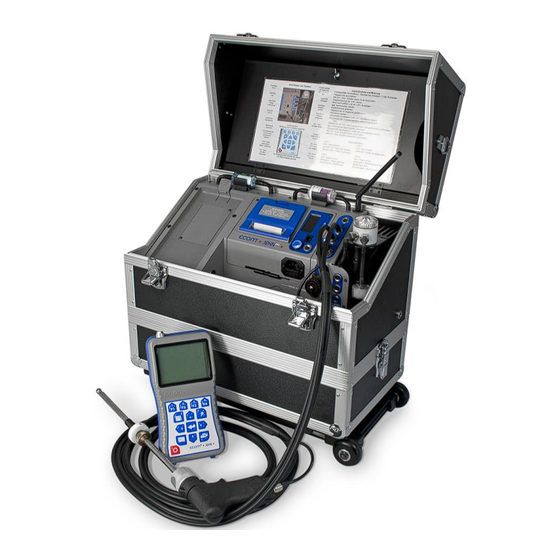
Base unit
Hide thumbs
Also See for J2KN PRO:
- Operating instructions manual (58 pages) ,
- Operation manual (44 pages) ,
- Quick manual (12 pages)

Subscribe to Our Youtube Channel
Related Manuals for Ecom J2KN PRO


Summary of Contents for Ecom J2KN PRO
- Page 1 Operations Manual version 3.6.2 ECOM America Ltd, 1628 Oakbrook Drive, Gainesville, GA 30507 Toll free (877) 326-6411 Phone (770) 532-3280 Fax (770) 532-3620 w ww . ec o mus a . c om...
- Page 2 Page 2...
-
Page 3: Table Of Contents
J2KN P ESIGN AND OW IT ORKS 1. Important Things to Remember …………………………………………4 2. Instrument Design 2.1. J2KN Pro Base Unit………………………………………………5 2.2. Remote Display Unit …………………………………………….6 2.3. Accessories…………………………………………………………7 2.4. Consumables……………………………………………………….8 3. Peltier Cooler ..…………………………………………………………………9 4. Gas Path Diagram…………………………………………………………….10 5. Power Supply…………………………………………………………………..11 6. -
Page 4: Important Things To Remember
1. Important Things to Remember The J2KN Pro meets the requirements of EPA CTM-030 and CTM-034 and ASTM D-6522 test- ing protocols for portable emission analyzers. In order to receive accurate measurements, please allow reading to stabilize for at least 2 minutes. -
Page 5: Instrument Design
2. Instrument Design 2.1 J2KN Pro Base Unit Draft/Pressure connection Main gas Info display connection (see 15. Control) Thermocouple Draft/Pressure connection connection Data cable Ambient air connection (used by ECOM temperature personnel only) sensor Analogue ON / OFF inputs button... -
Page 6: Remote Display Unit
2. Instrument Design (continued) 2.2 J2KN Pro Remote Display Unit Memory card slot WiFi antenna LCD display (If your antenna has a screen pink band, it is Bluetooth) Air temperature connection connection (not an antenna) Function Keys (See 8.1 Gas Analysis) -
Page 7: Accessories
2.3 Accessories e-Comply Testing Software Calibration Gas Kits Part no. 9038001H Part no. available upon request (Records mass emissions in g/bhp-hr, lbs/hr, & tons/year) Probe Shield 15ft/30ft Heated Sample Line Part no. 3025006G Part no. 7952501H (Custom lengths available (Recommended for high temp from 0 to 100ft) applications to protect grip) Tail Pipe Probe Assembly... -
Page 8: Consumables
200/PK - Round smoke Soot Test Paper 3003168G test filters for smoke (200/PK) dot test Soot Test Chart with 0- Soot Test Chart 3002970G 9 Grayness Scale *Please consult the J2KN Pro Parts List PDF for a list of all parts. Page 8... -
Page 9: Peltier Cooler
Monitoring Electrodes Inlet Water drain J2KN Pro must be plugged in for the Peltier cooler to operate. Exhaust gas with a temperature above dew point is intro- duced into a spiralling gas path with a coated metal surface of good thermal conductivity. The hot gas radiates its heat to... -
Page 10: Gas Path Diagram
4. Gas Path Diagram Response Time After inserting the probe into the sample gas, there is a short delay before the values start changing since the gas has to pass through the sampling system. This is referred to as response time, and it usually takes about 4-6 seconds for the readings to start to change. -
Page 11: Power Supply
5. Power Supply The J2KN Pro base unit has an internal power supply, and it is recommended to always run the unit on AC power. For testing locations where an AC plug-in is not available, the instrument can be operated from 6-8 hours on battery power when fully charged. -
Page 12: Radio Communication
6. Radio Communication The J2KN Pro base unit communi- Unlock cates wirelessly to the remote display unit via radio transmisision. To unlock the remote control unit, press on the tab to unlock and release from the cradle on the base unit. -
Page 13: Emissions Analysis And Recording 7. J2Kn Pro Start-Up
7. J2KN Pro Start-up Make sure the probe is in fresh air when you turn on the J2KN Pro. Gas analysis Radio Link Averaging Display contrast: Quality Indicator Lighten F1 Draft/Pressure Darken F2 Soot Test Automatic meas. Battery Charging Adjustments... -
Page 14: Emissions Measurement
8. Emissions Measurement 8.1 Gas Analysis Calibrate the sensors before each emission test for best results. After the 1-minute auto-zeroing phase, the instrument switches to Gas Analysis mode. The measurement values can be viewed on 3 display pages: a zoomed in 4-line display and 2 full 9-line displays. -
Page 15: Gas Analysis
8.1 Gas Analysis (continued) Heated Probe If you are testing in a cold temperature environment, you may require a heated probe so that condensation does not form (or freeze) in the probe or probe grip. To turn on the heated probe, go to Adjustments>Internal>Probe heat- ing>F1. -
Page 16: Printing
8.2 Printing Wait for the measurement values to stabilize for at least 2 minutes before printing the results. Quick Print The easiest and quickest way to print is to press <F2> for quick print, which immediately prints the measurement values currently on the screen. -
Page 17: Soot Test
To turn probe heating on, go to Adjustments > Internal > Probe heating > F1 J2KN Pro must be plugged in for the probe heating function to activate. Allow 3 minutes for the probe to heat up before soot test. -
Page 18: Capturing Data On Memory Card
Datalogger -> “Finish dl? Are you sure?” -> Press F1. Each data file will be saved separately as J2KDL-00, J2KDL-01, etc. Open in Microsoft Excel. You can also import the data from the SD card into ECOM’s free DAS 5 software to create formal reports. Page 18... -
Page 19: Averaging Tests
10. Averaging Tests The Averaging function allows you to take a sample of emissions data and compute an average over time. 1. Go to Averaging -> Select Meas. Time Averaging Start measurement 2. Input total measuring time in minutes or Meas. -
Page 20: Software Communication
11. Software Communication If you need help with installation or operation of your DAS or e-Comply software, please consult the User Manual for your software product. If you are having trouble communicating from the analyzer to a computer, please check the following: Adjustments >... -
Page 21: Frequently Asked Questions
12. Frequently Asked Questions In the Control screen, all important instru- Where do I find important in- ment information is shown (e.g. battery volt- strument information? age, sensor values, serial number, next ser- vice date, operation hours, etc.). The life span depends on the operating hours How long is the life span of the and the instrument equipment. -
Page 22: Frequently Asked Questions
The water is not pumping not pinched. If necessary, open up the unit and out of the water trap bowl check the rollers in the white housing. Call ECOM service for assistance. When trying to connect using Check these 3 items: software, the analyzer is not 1-Adjustments ->... -
Page 23: Draft/Pressure
13. Draft/Pressure A trend indication for the draft conditions in the exhaust channel is displayed in the Gas Analysis screen. Note that the pressure sensor tends to drift because of its sensitivity, and it is necessary to calibrate the sensor immediately before sam- pling to get an accurate measurement. -
Page 24: Adjustments
14. Adjustments (continued) parts per million mg/m3 milligrams per cubic meter mg/kWh %O2 Corrected milligrams per kilowatt-hours corrected to O2% mg/MJ %O2 Corrected milligrams per megajoules corrected to O2% ppm %O2 Corrected parts per million corrected to O2% mg/m3 %O2 Corrected milligrams per cubic meter corrected to O2% lbs/mmBTU %O2 Corrected pounds per million BTU corrected to O2%... -
Page 25: Internal
14.1 Internal Printout contrast (Go to Adjustments > Internal) Reload function Print contrast Key beep Choose print contrast from 0-9 Graphic menu Reload function Probe heating Choose remote unit battery recharging Quit with: settings (see 5. Power Supply) Power saving mode Key beep Language: English Press F1/F4 to turn key beep on/off... - Page 26 14.1 Internal (continued) For DAS 5 & e-Comply: Set Baud rate to 38400 Set Protocol to Enhanced WLAN (if applicable) Wireless Local Area Network. If you have internal WiFi, this option will appear and the IP address will display at the bottom -Access point: turn on/off internal WiFi -Auto connect: if turned on, WiFi will intitiate upon start-up -Channel: change the WLAN channel if interference occurs...
-
Page 27: Control
15. Control The electrochemical sensors change their output values over time based on frequency of use. The J2KN-Pro is pro- grammed to monitor the sensors and correct drifts. If the drifts and the correlated measurement errors increase, an er- ror message is displayed and it is time to change the sensor. The control menu displays the status of the sensors, batter- ies, radio quality, error count, number of times the J2KN-Pro has started up, and other analyzer information. -
Page 28: Maintenance Tips
16. Maintenance Tips Only use sensors, filters, and filter media provided by ECOM. Do not use desiccant! 16.1 Filters Particulate filter (water trap filter) Unscrew the cover of the water trap and check the particu- late filter for grayness. Change the filter when it is dark gray. -
Page 29: Sample Line And Probe
16.1 Filters (continued) Ventilation filter The ventilation filter should be changed if the filter has a darkness of 2-3 on the soot chart scale. Use a screwdriver to pry open the filter holder from the slots on each side. Change the filter cartridge and refasten the filter holder. -
Page 30: Sensors
16.3 Sensors (continued) The CO sensor is protected from exposure to high con- centrations by the automatic CO bypass pump. If the limit value of 4000 ppm is exceeded, a second pump switches on and purges the sensor with fresh air. 14.4 Printer Paper To change the printer paper, please follow these steps: 1. -
Page 31: How To Change Sensors
17. How to Change Sensors Improper installation voids warranty! Please mark connector when removing old sensor and insert new sensor into correct connector to prevent destruction of the sensor and main board. 17.1 How to Change O2 Sensor Step 1: Step 2: Use a T-10 The O2... -
Page 32: A5F Co Sensor
17.2 How to Change A5F CO Sensor Improper installation voids warranty! Please mark connector when removing old sensor and insert new sensor into correct connector to prevent destruction of the sensor and main board. Step 1: Step 2: Use T-10 torx The A5F CO wrench to sensor is in... -
Page 33: A5F Co Sensor
17.2 How to Change A5F CO Sensor (continued) Step 5: Step 6: Pop open the After the gray cap cap is using a small removed, screwdriver slide the sensor out Use the side of the of the hous- housing as ing as a shown here leverage... -
Page 34: Mem Co Sensor
18. How to Calibrate Sensors For best results, the calibration gas concentration should be as close to the expected levels of emissions as possible. However, because each sensor is linear through a nominal range, one calibration gas concentration can be used for a reasonably wide range of emission levels. -
Page 35: No, No2, So2, & High Co Sensors
18. How to Calibrate Sensors (continued) On-Demand Regulator: (Recommended) Use an on-demand regulator which uses the analyzer pump draw to establish flow. Connect the on-demand regulator to the sample train and open the cylinder valve. The analyzer pump controls the flow as to not over or under pressurize the sensors. -
Page 36: Flow Velocity Measurement (Option)
First, the Pitot factor must be entered in the Adjustments menu to get the correct flow rate calculation. Input 0.93 for the Pitot factor if you are using a standard ECOM probe. To do this, go to: Adjustments > Internal > Pitot factor... -
Page 37: Technical Data
20. Technical Data Parameter Range Principle 0 ... 21.0 vol-% Electrochemical 0 ... 4000 ppm Electrochemical CO% (Option) 4000 ... 63000 ppm Electrochemical 0 ... 5000 ppm Electrochemical 0 ... 500 ppm Electrochemical (Option) 0 ... 5000 ppm Electrochemical (Option) 0 ... - Page 38 21. Description of Data Fields using J2KN-Pro Data Logging onto Memory Card File format: J2KDL-xx.csv (comma-separated-values) Column Description Remark / Example Date DD.MM.YYYY Time HH:MM:SS 0.0 – 21.0 O2 in vol.% 0 – 4000 CO in ppm 0 – 4000 NO in ppm 0 –...
- Page 39 22. Calculations Carbon Dioxide (CO2) Range=0-CO2max (21 – O measured) = CO Combustion Efficiency (Eta) Range=0-99.9% - ( A1 + B) x (T Efficiency = Eta – T Note: A1, B, CO max & Eta are constants based on fuel type. Losses Range=0-99.9% Losses = 100 –...
- Page 40 UGGED ELIABLE CCURATE ECOM A MERICA 1628 O AKBROOK RIVE , GA 30507 AINESVILLE (877) 326-6411 OLL FREE (770) 532-3280 HONE (770) 532-3620 ecom.info@ecomusa.com w w w . e co m us a . co m Page 40...
Need help?
Do you have a question about the J2KN PRO and is the answer not in the manual?
Questions and answers