Tele Radio Panther PN-TX-MX8B Manual
Hide thumbs
Also See for Panther PN-TX-MX8B:
- Installation instructions manual (46 pages) ,
- Manual (92 pages)

Related Manuals for Tele Radio Panther PN-TX-MX8B


Summary of Contents for Tele Radio Panther PN-TX-MX8B
- Page 1 Panther Installatie-instructies Zender PN-TX-MX8B (PN-T19-2) IM-PN-TX103-A01-NL Taal: Nederlands (vertaling uit het Engels)
-
Page 2: Table Of Contents
INHOUD Hoofdstuk 1: KLANTINFORMATIE Hoofdstuk 2: FUNCTIONELE VEILIGHEID Hoofdstuk 3: PRODUCTBESCHRIJVING Voorkant zender Achterkant zender Technische gegevens Frequentieband Hoofdstuk 4: INSTALLATIEHANDLEIDING Starten van de zender De zender uitschakelen Uitloggen De zender in de ontvanger registreren Alle zenders uit de ontvanger wissen Vervangen Automatische uitschakeling Tonen van het kanaal... -
Page 3: Hoofdstuk 1: Klantinformatie
INSTALLATIE EN CONFIGURATIE VAN DE PRODUCTEN AANDACHTIG. Deze instructies worden door Tele Radio AB gepubliceerd en zijn niet onderhevig aan enige garantie. De instructies kunnen door Tele Radio AB te allen tijde en zonder nadere aankondiging worden ingetrokken of gewijzigd. Correcties en aanvullingen worden gepubliceerd in de nieuwste versie van de instructies. - Page 4 WAARSCHUWINGEN & BEPERKINGEN WAARSCHUWING! Afstandsbedieningen van Tele Radio AB worden vaak ingebouwd in bredere toepassingen. We raden aan om het systeem zo nodig te voorzien van een bedrade noodstop. LET OP! We raden aan om de functionaliteit van de stopknop regelmatig te testen (minimaal na elke 200 gebruiksuren).
- Page 5 Tele Radio AB streeft ernaar het gebruik van gevaarlijke stoffen tot een minimum te beperken, hergebruik en recycling te bevorderen en emissie naar lucht, grond of water te beperken. Zodra er een commercieel haalbaar alternatief beschikbaar komt, streeft Tele Radio AB ernaar het gebruik van stoffen en materialen die een gevaar betekenen voor het milieu, de gezondheid of de veiligheid te beperken of te stoppen.
-
Page 6: Hoofdstuk 2: Functionele Veiligheid
Hoofdstuk 2: FUNCTIONELE VEILIGHEID HOOFDSTUK 2: FUNCTIONELE VEILIGHEID LET OP! De informatie in dit hoofdstuk geldt alleen voor de hieronder aangegeven producten. Veiligheidsfunctie De veiligheidsgerelateerde stopfunctie in het radiosysteem voldoet aan EN 13849-1:2008, categorie 3 PLd. De stoprelais op de ontvanger worden aangestuurd door de noodstop op de zender. Als de noodstop wordt ingedrukt, onderbreken de stoprelais de stroom naar de veiligheidsgerelateerde toepassing. - Page 7 Hoofdstuk 2: FUNCTIONELE VEILIGHEID WAARSCHUWING! Alle veiligheidsgerelateerde parameters moeten als volgt geconfigureerd zijn om te voldoen aan de toepasselijke veiligheidseisen: Het systeem moet geconfigureerd zijn voor de continue radiomodus Alle relais moeten zijn uitgeschakeld als de radioverbinding niet actief is ...
-
Page 8: Hoofdstuk 3: Productbeschrijving
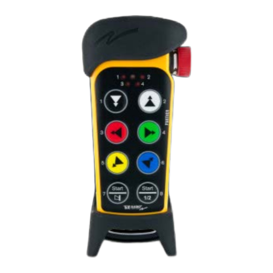
Hoofdstuk 3: PRODUCTBESCHRIJVING HOOFDSTUK 3: PRODUCTBESCHRIJVING VOORKANT ZENDER 1. Rubberen bescherming 2. Noodstop 3. LED 2 (rood) 4. LED 4 (rood) 5. LED 1 (rood) 6. LED 3 (rood) 7. Bovenste LED (rood, groen) 8. Knop 1 9. Knop 3 10. -
Page 9: Technische Gegevens
TECHNISCHE GEGEVENS Aantal knoppen 8 x 2-staps knoppen Batterij 3 x 1,5 V AAA / LR03 in batterijpak D4-3 Aan/uit-schakelaar Radiocommunicatie Simplex Afmetingen 85 x 193 x 43 mm / 3,4 x 7,7 x 1,7 in Gewicht 300 g / 0,7 lbs Frequentieband 2405-2480 MHz Aantal kanalen... -
Page 10: Hoofdstuk 4: Installatiehandleiding
Hoofdstuk 4: INSTALLATIEHANDLEIDING HOOFDSTUK 4: INSTALLATIEHANDLEIDING STARTEN VAN DE ZENDER 1. Zorg ervoor dat de noodstop is ingedrukt. 2. Draai en trek de noodstop uit. De bovenste LED gaat branden (groen als de batterijcapaciteit goed is, rood als de batterij opge- laden moet worden), LED's 3 en 4 knipperen (rood). - Page 11 Uitloggen van ontvanger Deze uitlogoptie wordt gebruikt wanneer een verloren of beschadigde zender moet worden uitgelogd via de ontvanger. 1. Druk op de 'Select'-knop van de ontvanger. LED 10 gaat branden (oranje). 2. Ingedrukt houden (minimaal 4 seconden). LED 10 gaat uit.
-
Page 12: De Zender In De Ontvanger Registreren
DE ZENDER IN DE ONTVANGER REGISTREREN WAARSCHUWING! Zorg ervoor dat alleen zenders die u wilt gebruiken geregistreerd staan in de ontvangers. LET OP! Om een radioverbinding tussen de zender en de ontvanger tot stand te brengen, moeten beide eenheden in dezelfde radiomodus staan. ... -
Page 13: Vervangen
VERVANGEN Een geregistreerde zender kan vervangen worden door een andere zender zonder toegang te hebben tot de ontvanger. Gebruik de nieuwe zender die de oude zender vervangt. 1. Zorg ervoor dat de noodstop is ingedrukt. 2. Druk op knop 8. Houd de knop ingedrukt. 3. -
Page 14: Automatische Uitschakeling
AUTOMATISCHE UITSCHAKELING LET OP! Alleen voor continue radiomodus. Met een automatische uitschakeling kan batterijcapaciteit worden uitgespaard, door de zender na een vooringestelde periode van inactiviteit automatisch uit te schakelen. De automatische uitschakeltijd instellen 1. Zorg ervoor dat de noodstop is ingedrukt. 2. -
Page 15: Tonen Van Het Kanaal
TONEN VAN HET KANAAL 1. Zorg ervoor dat de noodstop is ingedrukt. 2. Druk op knop 8. Houd de knop ingedrukt. 3. Draai en trek de noodstop uit. 4. Laat knop 8 los. De bovenste LED knippert (groen). 5. BINNEN 1 MINUUT NA HET UITTREKKEN VAN DE NOODSTOP: Voer de code in: 1-2-3-4 (druk op de knoppen 1, 2, 3, 4). -
Page 16: Load Select Mode
Voorbeeld kanaal 20: druk op knop 2 voor het eerste cijfer. Voor nul: druk op knop 8, houd ze ingedrukt, druk op knop 4, laat knop 4 los en laat knop 8 los. Druk op... voor cijfer... knop 1 knop 2 knop 3 knop 4... - Page 17 LOAD SELECT MODE 0-4 Load select mode 0 Load select mode 1 Load select mode 2 Load select mode 3 Load select mode 4 - 17 -...
- Page 18 LADEN BIJ OPSTARTEN LET OP! Zorg ervoor dat de Load select mode geselecteerd is VOORDAT Laden bij opstarten wordt geselecteerd. 1. Zorg ervoor dat de noodstop is ingedrukt. 2. Druk op knop 8. Houd de knop ingedrukt. 3. Draai en trek de noodstop uit. 4.
-
Page 19: Radiomodus
RADIOMODUS LET OP! Om een radioverbinding tussen de zender en de ontvanger tot stand te brengen, moeten beide eenheden in dezelfde radiomodus staan. Deze zender staat standaard in de continue radiomodus. De zender begint continu te zenden zodra deze wordt opgestart. De zender stopt met zenden als de stopknop wordt ingedrukt. Als het systeem in de continue radiostand staat, worden knoppen 7 en 8 gebruikt als startknoppen. -
Page 20: Ga Naar De Menustand
GA NAAR DE MENUSTAND 1. Zorg ervoor dat de noodstop is ingedrukt. 2. Druk op knop 8. Houd de knop ingedrukt. 3. Draai en trek de noodstop uit. 4. Laat knop 8 los. De bovenste LED knippert (groen). 5. BINNEN 1 MINUUT NA HET UITTREKKEN VAN DE NOODSTOP: Voer de code in: 1-2-3-4 (druk op de knoppen 1, 2, 3, 4). -
Page 21: Hoofdstuk 5: Batterijhandleiding
Ongeveer 150 uur (afhankelijk van Ongeveer 100 uur met alkaline instellingen) (afhankelijk van instellingen) Opladen Opladen in de lader van Tele Radio Niet opladen in de lader van Tele Radio AB. De batterijen in het batterijpak verwisselen. Oplaadtemperatuur 0 – +45 °C / +32 – +113 °F Niet van toepassing ... - Page 22 BATTERIJEN VERVANGEN Batterijen vervangen in batterijpak D4-3 WAARSCHUWING! Het batterijpak D4-3 mag niet worden opgeladen in de oplaadunit van Tele Radio AB of in enige andere oplader. 1. Haal het batterijpak uit de achterkant van de zender.
-
Page 23: Hoofdstuk 6: Garantie, Service, Reparatie En Onderhoud
Op de producten van Tele Radio AB wordt garantie verleend op materiaal-, constructie- en fabricagefouten. Tijdens de garantieperiode kan Tele Radio AB ervoor kiezen het product of de defecte onderdelen te vervangen. Garantiewerkzaamheden dienen te worden uitgevoerd door Tele Radio AB of door een erkend, door Tele Radio AB aangewezen servicecentrum. -
Page 24: Hoofdstuk 7: Wettelijke Informatie
Dit product voldoet aan de essentiële vereisten van richtlijn 1995/5/EG van het Europese Parlement en van de Raad. De meest recente versie van de Verklaring van overeenstemming kan worden gedownload van de website van Tele Radio AB. FCC STATEMENT ... - Page 25 Hoofdstuk 7: WETTELIJKE INFORMATIE Les antennes installées doivent être situées de facon à ce que la population ne puisse y être exposée à une distance de moin de 20 cm. Installer les antennes de facon à ce que le personnel ne puisse approcher à...
-
Page 26: Hoofdstuk 8: Frequente Termen
Hoofdstuk 8: FREQUENTE TERMEN HOOFDSTUK 8: FREQUENTE TERMEN Configuratie-id Numerieke code opgeslagen in de zender en de ontvanger. De ontvanger kan alleen bestuurd worden door een zender met de juiste configuratie-id. Continue radio- In de continue radiomodus zendt de zender continu wanneer deze is ingeschakeld. modus ... - Page 27 (Deze pagina is opzettelijk leeg gelaten) ...
- Page 28 Deze installatie-instructies kunnen worden gewijzigd zonder kennisgeving vooraf. Download de meest recente installatie-instructies op www.tele-radio.com...
- Page 33 Panther Installation instructions Transmitter PN-T19-2 IM-PN-TX103-A03-EN Language: English (original)
- Page 34 CONTENTS CHAPTER 1: CUSTOMER INFORMATION Thank you for purchasing a Tele Radio AB product About this document Warnings & restrictions CHAPTER 2: FUNCTIONAL SAFETY Safety function Eligible products Installation Configuration Interface CHAPTER 3: PRODUCT DESCRIPTION Transmitter front Transmitter back Technical data Frequency band CHAPTER 4: OPERATION Register the transmitter in the receiver Start the transmitter...
-
Page 35: Chapter 1: Customer Information
Read all instructions and warnings carefully before mounting, installing and configuring the products. These instructions have been published by Tele Radio AB and are not subject to any guarantee. The instructions may be withdrawn or revised by Tele Radio AB at any time and without further notice. -
Page 36: About This Document
ABOUT THIS DOCUMENT Every care has been taken in the preparation of this manual. Please inform Tele Radio AB of any inaccuracies or omissions. These installation instructions cover general safety issues, main technical specifications, standard installation, configuration and operating instructions, general troubleshooting and battery information. - Page 37 Operation Only qualified personnel should be permitted to access the transmitter and operate the equipment. Make sure that the user satisfies the age requirements in your country for operating the equipment. Make sure that the user is not under the influence of drugs, alcohol and medications. ...
-
Page 38: Chapter 2: Functional Safety
CHAPTER 2: FUNCTIONAL SAFETY NOTE! The information in this section applies only to the products specified below. SAFETY FUNCTION The safety-related stop function in the radio system complies with EN 13849-1:2008 Category 3 PLd. The stop relays on the receiver unit are controlled by the stop button on the transmitter unit. When the stop button is pressed, the stop relays interrupt the power to the safety-related application. -
Page 39: Interface
1. Stop relays 2. PLd status LED NOTE! All safety-related parameters must be configured as follows in order to comply with the appointed safety requirements: The system must be configured in continuous radio mode All relays must be switched off when the radio link is down ... -
Page 40: Chapter 3: Product Description
CHAPTER 3: PRODUCT DESCRIPTION TRANSMITTER FRONT PN-T19-2 1. Rubber cover 2. Stop button 3. LED 2 (red) 4. LED 4 (red) 5. LED 1 (red) 6. LED 3 (red) 7. Top LED (red, green) 8. Button 1 9. Button 3 10. -
Page 41: Technical Data
TECHNICAL DATA Number of buttons 8 x 2-step buttons Battery 3 x 1.5 V AAA / LR03 in battery pack D4-3 I/O switch Radio communication Simplex Dimensions 85 x 193 x 43 mm / 3.4 x 7.7 x 1.7 in Weight 300 g / 0.7 lbs Frequency band 2405–2480 MHz... -
Page 42: Chapter 4: Operation
CHAPTER 4: OPERATION To control a receiver, the transmitter must be registered and logged in to the receiver. If another transmitter is already logged in to the receiver, it must be logged out before a different transmitter can be logged in. If no transmitter is logged in to a receiver, any registered transmitter will automatically log in when sending radio signals to the receiver. -
Page 43: Start The Transmitter
START THE TRANSMITTER When starting the transmitter, it will automatically log in to the receiver(s) it has been registered in, provided that no other transmitter is already logged in to the receivers(s). If the transmitter was not logged out after the last session, it will remain logged in when starting a new session. NOTE! More than one transmitter can be registered in the receiver, but only one transmitter can be logged in at a time. - Page 44 Quick logout NOTE! Quick logout can only be performed when the transmitter is on and the radio link is up. The Quick logout will log the transmitter out from all receivers that are part of the radio session. 1. Press button 7. Keep pressed. 2.
-
Page 45: Chapter 5: Configuration Settings
CHAPTER 5: CONFIGURATION SETTINGS ENTER MENU MODE 1. Make sure that the stop button is pressed. 2. Press button 8. Keep pressed. 3. Twist and pull out the stop button. 4. Release button 8. The top LED flashes (green). 5. WITHIN 1 MINUTE OF PULLING OUT THE STOP BUTTON: Enter the code: 1–2–3–4 (press buttons 1, 2, 3, 4). -
Page 46: Show Channel
SHOW CHANNEL 1. Make sure that the stop button is pressed. 2. Press button 8. Keep pressed. 3. Twist and pull out the stop button. 4. Release button 8. The top LED flashes (green). 5. WITHIN 1 MINUTE OF PULLING OUT THE STOP BUTTON: Enter the code: 1–2–3–4 (press buttons 1, 2, 3, 4). -
Page 47: Switch Channel
SWITCH CHANNEL 1. Make sure that the stop button is pressed. 2. Press button 8. Keep pressed. 3. Twist and pull out the stop button. 4. Release button 8. The top LED flashes (green). 5. WITHIN 1 MINUTE OF PULLING OUT THE STOP BUTTON: Enter the code: 1–2–3–4 (press buttons 1, 2, 3, 4). -
Page 48: Radio Mode
RADIO MODE NOTE! To establish a radio link between the transmitter and the receiver, both units must be set to the same radio mode. This transmitter is set to continuous radio mode by default. The transmitter starts to transmit continuously as soon as it is started. The radio transmission ends when the stop button is pressed. When the system is in continuous radio mode, buttons 7 and 8 are used as start buttons. -
Page 49: Automatic Shutdown
AUTOMATIC SHUTDOWN NOTE! Only for continuous radio mode. Automatic shutdown can save battery capacity by automatically switching the transmitter off following a preset period of inactivity. Setting the automatic shutdown time 1. Make sure that the stop button is pressed. 2. -
Page 50: Replace
REPLACE A registered transmitter can be replaced with another transmitter without having access to the receiver. Use the transmitter that will replace the old transmitter to perform the following instructions. Do not perform this action when the receiver is in a session with another transmitter. -
Page 51: Load Select Mode
LOAD SELECT MODE NOTE! Only for continuous radio mode. 1. Make sure that the stop button is pressed. 2. Press button 8. Keep pressed. 3. Twist and pull out the stop button. 4. Release button 8. The top LED flashes (green). 5. - Page 52 Load select mode 0–4 Load select mode 0 Load select mode 1 Load select mode 2 Load select mode 3 Load select mode 4 - 20 -...
-
Page 53: Load At Start-Up
LOAD AT START-UP NOTE! Be sure to select Load select mode BEFORE selecting Load at start-up. 1. Make sure that the stop button is pressed. 2. Press button 8. Keep pressed. 3. Twist and pull out the stop button. 4. -
Page 54: Chapter 6: Battery Guide
CHAPTER 6: BATTERY GUIDE BATTERY PRECAUTIONS Carefully read through the following safety instructions and warnings before using, charging or disposing of the batteries. Batteries contain flammable substances such as lithium or other organic solvents, which may result in overheating, rupture or combustion. Failure to read and follow the below instructions may result in fire, personal injury and damage to property if charged or used improperly. -
Page 55: Battery Information
– *Not included. CHANGE BATTERIES IN BATTERY PACK D4-3 NOTE! Do not charge battery pack D4-3 in the Tele Radio AB charger unit or in any other charger. 1. Remove the battery pack from the back of the transmitter. -
Page 56: Chapter 7: Guarantee, Service, Repairs And Maintenance
Tele Radio AB products are covered by a guarantee/warranty against material, construction and manufacturing faults. During the guarantee/warranty period, Tele Radio AB may replace the product or faulty parts. Work under guarantee/warranty must be carried out by Tele Radio AB or by an authorized service centre specified by Tele Radio AB. -
Page 57: Chapter 8: Regulatory Information
Applies to: PN-T19-2 CE MARKING Hereby, Tele Radio AB, declares that the radio equipment type(s) listed above is/ are in compliance with Directive 2014/53/EU. The latest version of the complete EU Declaration of Conformity is available on the Tele Radio AB website, www.tele-radio.com. -
Page 58: Ic Statement
IC STATEMENT This product complies with Industry Canada's licence-exempt RSSs. Operation is subject to the following two conditions: (1) This device may not cause interference; and (2) This device must accept any interference, including interference that may cause undesired operation of device. Le présent appareil est conforme aux CNR d’Industrie Canada applicables aux appareils radio exempts de licence. -
Page 59: Annex A: Frequent Terms
ANNEX A: FREQUENT TERMS Numerical code stored in both the transmitter and receiver unit. The receiver unit Configuration ID can only be controlled by a transmitter with the correct configuration ID. Continuous radio When in continuous radio mode the transmitter unit transmits continuously when mode it is switched on. - Page 60 These installation instructions are subject to change without prior notice. Download the latest installation instructions from www.tele-radio.com...
Need help?
Do you have a question about the Panther PN-TX-MX8B and is the answer not in the manual?
Questions and answers