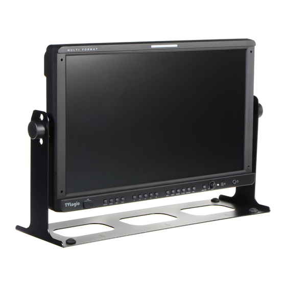
TVLogic LVM-170A Operation Manual
Multi format broadcast lcd monitor
Hide thumbs
Also See for LVM-170A:
- Operation manual (44 pages) ,
- Operation manual (33 pages) ,
- Operation manual (33 pages)
Table of Contents
Advertisement
Advertisement
Table of Contents

Related Manuals for TVLogic LVM-170A


Summary of Contents for TVLogic LVM-170A
- Page 1 Multi Format Broadcast LCD Monitor LVM-170A LVM-171A...
-
Page 3: Table Of Contents
Contents 1. Caution 2. Main Features 3. Controls & Functions 4. Menu Organization & Adjustment 5. Menu Operations [1] PICTURE [2] COLOR [3] MARKER [4] GPI/UMD [5] WAVEFORM [6] AUDIO [7] DISPLAY & SET 6. Firmware Upgrage 7. Button Functions 8. -
Page 4: Caution
1. Caution Always use set voltage. • • Do not attempt to service the product yourself. ● Removing covers can expose you to high AC 100 ~ 240V (1.6A/50~60Hz) ● voltage and other dangerous conditions. DC 12/24V(MAX 6A) ● Request a qualifi ed service person to perform servicing. - Page 5 1. Caution • • When mounting the product on a wall or • • When relocating the product placed on a cart, ceiling, be sure to install the product it must be moved with the utmost care. according to the method recommended by the Sudden stops, excessive force and uneven fl oor manufacturer.
-
Page 6: Main Features
2. Main Features LVM-170A/171A Monitors contain the following features : Compatible with varied SDI signals Wide screen compatible ● ● - The product is compatible with varied - Wide screen for 16:9 aspect monitoring. SD/HD/3G(A/B)-SDI 480i,576i,720p,1080i/p, 1080psf. AC/DC Compatible ●... -
Page 7: Controls & Functions
3. Controls & Functions LVM-170A : FRONT MENU/EXIT ENTER/UP/DOWN SDI-B POWER SDI-A PHONE JACK DIGITAL ANALOG INFO. BLUE ONLY H/V DELAY MARKER ASPECT SCAN LVM-170A : REAR HDMI CVBS DVI-I SDI-A IN SDI-B IN SDI OUT LAN OUT LAN IN... - Page 8 3. Controls & Functions LVM-170A : FRONT [USB] [F1 ~ F5] Button/Lamp ● ● - Updates new fi rmware and color calibration. - Performs the function that the user set as hot-keys. - The selectable the hot-key menu comes up [ANALOG] Button/Lamp ●...
- Page 9 3. Controls & Functions LVM-170A : FRONT [MARKER] Button/Lamp [MENU/EXIT] Button/Lamp ● ● - Used to activate/deactivate the Marker. - Activates OSD menu. - The Marker is normally displayed when you select Aspect ratio you want in OSD Menu. [ENTER/UP/DOWN] Knob ●...
- Page 10 [RS422 IN/OUT] (RJ-45) ● through signal cable. Please check if the AC - Controls the monitor by a protocol provided power source and the power extender or by TVLogic or supports TSL protocol. power distributor is grounded. 10 Multi Format LCD Monitor...
- Page 11 3. Controls & Functions LVM-171A : FRONT POWER SOURCE SCAN ASPECT MARKER MENU/ EXIT UP/DOWN /ENTER AUDIO OUT LVM-171A : REAR CVBS DVI-I HDMI SDI-A IN SDI-B IN SDI OUT ~AC IN DC 12V IN RS-422 IN REMOTE LAN IN RS-422 OUT AUDIO IN LAN OUT Multi Format LCD Monitor 11...
- Page 12 AFD the phone jack. data, the marker is displayed automatically. [TALLY] Lamp ● - Tally lamp that can be toggled in Green or Red using the REMOTE(RJ-45) port or TVLogic’s control program(Observer). 12 Multi Format LCD Monitor...
- Page 13 [RS422 IN/OUT] (RJ-45) ● - Controls the monitor by a protocol provided [SDI-IN A] (BNC) ● by TVLogic or supports TSL protocol. - Signal input terminal for 3G/HD/SD SDI signal. ~ AC IN ● - 100 ~ 240V AC 50/60Hz [SDI-IN B] (BNC) ●...
-
Page 14: Menu Organization & Adjustment
4. Menu Organization & Adjustment [1] Menu Organization [3] Menu Adjustment Procedure The product may be controlled and set Menu control sequence follows the order ● ● system-wise through OSD displayed on below: the screen. 1. Press MENU button to bring the OSD menu on the screen. -
Page 15: Menu Operations
5. Menu Operations [1] PICTURE (LVM-170A) NTSC Setup ● - The item sets NTSC IRE value for 0(Zero setup) or 7.5 IRE. - It is activated in COMPOSITE 1/2/3 or S-VIDEO only NTSC signal is input. Key Lock ● - The item locks all buttons except for power, source change and menu button in front of the monitor. - Page 16 5. Menu Operations [1] PICTURE (DVI ANALOG) Brightness Image Position ● ● - The item controls the degree of brightness - The items moves the picture position for up/ between -100~100. down/left/right. #Brightness can be adjusted by using a control knob on the front of the monitor. Contrast ●...
-
Page 17: Color
5. Menu Operations [2] COLOR Color Copy ● - The item is used to copy pre-stored color temperature settings into a USER1/2/3 mode. - In USER mode, fi nd and select the color temperature to be used as a starting point of custom color temperature. - Page 18 5. Menu Operations [2] COLOR (LVM-171A) Camera LUT ● - Used to change the output Log video from the camera to the Rec 709 standard. - The mode will be changed as the following sequence. [LOG-C]-[C-LOG]-[S-LOG1]- [S-LOG2]-[S-LOG3]-[RED Gamma3]- [RED Gamma4] * Press the Function Button to activate/ deactivate the Gamma LUT function.
-
Page 19: Marker
5. Menu Operations [3] MARKER Fit Marker ● - The item activates the FIT MARKER function. - With FIT MARKER On the safety area is displayed relative to the marker in use. With FIT MARKER Off the safety area is displayed relative to the incoming source. - Page 20 5. Menu Operations [3] MARKER USER Marker H1 ● - The item controls the position of the fi rst user defi ned horizontal marker line. - Marker option USER needs to be selected. USER Marker H2 ● - The item controls the position of the second user defi ned horizontal marker line.
-
Page 21: Gpi/Umd
5. Menu Operations [4] GPI / UMD Menu Classifi - Settable Values cation NONE, ANALOG CHANNEL, HDMI CHANNEL, SDI-A/B CHANNEL TALLY RED, TALLY GREEN, BLUE ONLY, ASPECT HVDELAY, 16:9 MARKER, This product provides a REMOTE ● 15:9 MARKER, CONTROL mode. The user may connect 14:9 MARKER, RJ-45 jack to the REMOTE terminal on the 13:9 MARKER,... - Page 22 - The item sets the font size of UMD and the - The item sets the ID of each monitor for the size of UMD letter box. TVLogic control protocol or DYNAMIC UMD - The selectable items are [Small] and [Large]. using RS-422/485 communication.
- Page 23 D-UMD(D-8C) is set in UMD DISPLAY. - The selectable values are DEFAULT and USER COLOR. * Default : Original TVLogic managing method (VRT) * User color : Each user can set each tally color. - When user color is selected, TALLY1 COLOR ~ TALLY4 COLOR items are activated.
- Page 24 5. Menu Operations [4] GPI / UMD <Dynamic UMD Protocol (TSL V3.1)> * Transmission (18 Byte) (PC or Device -> Monitor) HEADER CONTROL DISPLAY DATA (1 BYTE) BYTE(1 BYTE) (16 BYTE) * [HEADER] : Display address (0~126) + 80 hex. * [CONTROL BYTE] bit 0 : Tally 1 (1=on, 0=off ) bit 1 : Tally 2 (1=on, 0=off )
- Page 25 5. Menu Operations [4] GPI / UMD Tally Type - Default ● - S-8C(Single 8 Character) & S-16C(Single 16 Character) Bit 1 Bit 1 Operation (Tally2) (Tally1) CHANNEL1 CHANNEL1 CHANNEL1 CHANNEL1 CHANNEL1 CHANNEL1 CHANNEL1 - D-8C(Dual 8 Character) Bit 1 Bit 1 Operation (Tally4)
-
Page 26: Waveform
- The item sets Waveform and Vectorscope. - The operation order is Waveform Color ● LVM-170A : Off , Waveform, Vectorscope, - Used to select the color of the waveform. Waveform YCbCr, Waveform RGB, - Available colors are Green and White. - Page 27 5. Menu Operations [5] WAVEFORM Luma(Y’) Zone Check ● - Analyzes Luma (Y’) of input signal and displays the analyzed area on the screen. - There are [Color Pattern] and [Zebra Pattern] methods to display it. - After every pixel Y’ level analyzing, it is displayed with a certain color or diagonal line in right index of the screen.
- Page 28 5. Menu Operations [5] WAVEFORM C Max ● - Sets the max. value of Chroma (C’) between 0~255. - The part exceeding the set value is displayed by red in Waveform and by blinking on the screen. C Min ● - Sets the min.
-
Page 29: Audio
5. Menu Operations [6] AUDIO Level Meter Group ● - Used to set the level meter group. - Available modes are as below. * 8CH/8CH Side : [G1+G2]-[G2+G3]-[G3+G4]- [G1+G3]-[G1+G4]-[G2+G4] * 4CH/4CH Side : [G1]-[G2]-[G3]-[G4] Level Meter Display (SDI Only) ● - The item controls display method of audio level meter - Available modes are PAIR and GROUP. - Page 30 5. Menu Operations [6] AUDIO Loudness log time ● - Used to set the log time. - Activates in the order : [8 Minute]-[16 Minute]-[32 Minute]-[1 Hour]-[2 Hour]-[4 Hour]-[8 Hour]-[24 Hour]. - Sets the time period of the Loudness log. - In the case of 8 Minute, the log is divided into 4 columns and each column corresponds to 2 minutes.
-
Page 31: Display & Set
5. Menu Operations [7] DISPLAY & SET( (LVM-170A) Key LED ● - The item turns on / off LED in front of the monitor. - Even though you turn off KEY LED, when you press LED button in front of the monitor, the LED is on and after 5 sec. - Page 32 [7] DISPLAY & SET (LVM-171A) Key LED ● - The item turns on / off LED in front of the monitor. - Even though you turn off KEY LED, when you press LED button in front of the monitor, the LED is on and after 5 sec.
- Page 33 5. Menu Operations [7] DISPLAY & SET TimeCode Enable ● - The item sets timecode. - Available modes are OFF, VITC and LTC. Focus Assist ● - The item makes you check which point your camera’s focus is on easily by showing a color on focused area.
- Page 34 5. Menu Operations [7] DISPLAY & SET S/W upgrade ● - fi rmware-updates with USB memory stick(Thumb drive). S/W upgrade start ● - When S/W upgrade is [On], the monitor detects USB memory stick, and update is available, it is activated. 34 Multi Format LCD Monitor...
-
Page 35: Firmware Upgrage
* During the update, the monitor screen is off , and nothing functions. * After the update, TVLogic logo shows up on the screen, and the monitor initializes. * Update can take 10~20min. depending on fi rmware kind. -
Page 36: Button Functions
7. Button Functions [1] ANALOG (LVM-170A) [2] DIGITAL INPUT (LVM-170A) LVM-170A monitor supports various LVM-170A monitor supports HDMI/DVI ● ● analog input signals. digital input signal. 1. Press [ANALOG] in front of the monitor and 1. Press [HDMI] in front of the monitor and activate OSD menu as the left photo. - Page 37 7. Button Functions [3] SDI INPUT (LVM-170A) [3] SOURCE INPUT(LVM-171A) LVM-170A series monitor supports two The LVM-171A supports various SDI ● ● HD/SD/3G-SDI inputs. signals (HD/SD/3G-SDI), Digital signals (HDMI/DVI Digital) and Analog signals 1. Press [SDI-A] or [SDI-B] in front of the (DVI Analog/Composite).
- Page 38 2 sec. and activate OSD menu as the left photo. 2. Select input you would like to use by Knob and press the knob. 3. Afterward, [F1]~[F5] perform the designated functions. <LVM-170A> <LVM-171A> 38 Multi Format LCD Monitor...
-
Page 39: Other Functions
8. Other Functions [1] SCAN The function can select various scan ● mode. Press [SCAN] in front of the monitor and ● change scan mode. 1. Press [SCAN] button continuously to activate various scan modes. 2. The following represents the diff erent types of scan mode. - Page 40 8. Other Functions [2] USER ASPECT Select [Aspect] mode in the OSD menu to ● activate the[User Aspect] mode. After activation, press the Knob to get ● ready for controlling. - Adjust the ratio using the Knob. # To adjust the 16:9 aspect ratio of 1920X1080 resolution into 2.35:1 aspect ratio, adjust the - Control range for width : width and height as 1920X817.
- Page 41 8. Other Functions [3] WAVEFORM / VECTORSCOPE Waveform / Vector VectorScope ● ● - This function sets the Waveform and - Displays the color components ‘B-Y’ and ‘R-Y’ Vectorscope. of the input signals onto the X-Y axis. - Activates in order Off , Waveform, - Two diff erent types of Vetorscopes are Vectorscope, Waveform wide, Waveform displayed according to SD or HD input...
- Page 42 8. Other Functions [4] LINE SELECT [5] ZOOM (Waveform/Vectorscope) Used to select specifi c Vertical Line for Used to magnify the input signal from 0% ● ● WaveForm/VectorScope. to 90%. - It is available when LINE WaveForm is Supports Zoom Width Scroll / Zoom ●...
- Page 43 8. Other Functions [6] LUMA(Y') ZONE CHECK Color Pattern Type Zebra Pattern Type ● ● - Displays the Luma(Y’) level of the input - Displays the pixels with designated Luma(Y’) image in colors. levels with zebra pattern. - Y’ ≥ 100% : Pixels with higher Y’ level than - Y’...
- Page 44 8. Other Functions [7] FOCUS ASSIST [8] RANGE ERROR Focus Assist function assigns a color to Pixels with Y’ or C’ levels exceeding the ● ● the pixels in the shape or boundary area designated levels of Y MAX, Y MIN, C MAX of the image to inform the user to make and C MIN shall blink.
- Page 45 8. Other Functions [9] INTERNAL PATTERN [10] INFO. Displays current status and function Displays internally generated test ● ● setting of the monitor. patterns. It displays when you press [Info.] in front ● - The pattern consists of ColorBar and Pluge+ of the monitor.
- Page 46 8. Other Functions [11] LOUDNESS The purpose of loudness control in programme exchange, in order to be uniform for ● diff erent sources and programme types. It is based on an Leq measurement employing K-weighting, which is a defi ned by The ●...
-
Page 47: Dvi / Hdmi Support Resolution
9. DVI / HDMI Support Resolution DVI ANALOG / DIGITAL /HDMI SUPPORT RESOLUTION DVI-ANALOG mode supports the following modes : ● Resolution Frequency 640 X 480 60Hz, 75Hz 720 X 400 70Hz 800 X 600 60Hz, 72Hz, 75Hz 1024 X 768 60Hz, 70Hz, 75Hz 1366 X 768 60Hz / 75Hz... -
Page 48: Product Specifi Cations
10. Product Specifi cations LVM-170A Size 17.3” Resolution 1920 X 1080 (16:9) Pixel Pitch 0.199(H) X 0.199(V) mm Color Depth 16.7M (8bit-D) Viewing Angle H : 178 degrees / V : 178 degrees Luminance of white 300 cd/ m (Center) - Page 49 10. Product Specifi cations LVM-171A Size 16.5” Resolution 1920 X 1080 (16:9) Pixel Pitch 0.1905(H) X 0.1905(V) mm Color Depth 1.07B (8bit+2bit FRC) Viewing Angle H : 178 degrees / V : 178 degrees Luminance of white 450 cd/ m (Center) Contrast Ratio 1500 : 1...
-
Page 50: Optional Accessories
11. Optional Accessories RACK MOUNT ANY DISPLAY UP TO 24” 8.4 inch 9 inc h 7 inch 15 inch 17 inch 21 inch 24 inch 50 Multi Format LCD Monitor... - Page 52 FOR MORE INFORMATION PLEASE VISIT : http://www.tvlogic.tv 12F, ACE HIGH-END 8, 84 Gasan digital 1-ro, Geumcheon-gu, Seoul, 08590, KOREA TEL : +82-70-8668-6611, FAX : 82-2-6123-3201, E-mail : sales@ t vlogic.co.kr...
Need help?
Do you have a question about the LVM-170A and is the answer not in the manual?
Questions and answers