Table of Contents
Advertisement
Quick Links
Advertisement
Table of Contents

Subscribe to Our Youtube Channel
Related Manuals for Advantech EBPC-5250


Summary of Contents for Advantech EBPC-5250
- Page 1 User Manual EBPC-5250 Embedded Industrial Computer Chassis for 5.25" Biscuit SBCs...
- Page 2 No part of this manual may be reproduced, copied, translated or transmitted in any form or by any means without the prior written permission of Advantech Co., Ltd. Information provided in this manual is intended to be accurate and reliable. How- ever, Advantech Co., Ltd.
- Page 3 This device complies with Part 15 of the FCC rules. Operation is subject to the following two conditions: this device may not cause harmful interference, and this device must accept any interference received, including interference that may cause undesired operation. EBPC-5250 User Manual...
- Page 4 Don't touch any components on the CPU card or other cards while the PC is on. Disconnect power before making any configuration changes. The sudden power surge as you connect a jumper or install a card may damage sensitive electronic components. EBPC-5250 User Manual...
- Page 5 Advantech has come to be known. Your satisfaction is our primary concern. Here is a guide to Advantech’s cus- tomer services.
- Page 6 Because of Advantech's high quality-control standards and rigorous testing, most of our customers never need to use our repair service. If an Advantech product is defec- tive, it will be repaired or replaced at no charge during the warranty period. For out- of-warranty repairs, you will be billed according to the cost of replacement materials, service time and freight.
- Page 7 Also, please notify the carrier. Retain the shipping carton and packing material for inspection by the carrier. After inspection, we will make arrangements to repair or replace the unit. EBPC-5250 User Manual...
- Page 8 EBPC-5250 User Manual viii...
-
Page 9: Table Of Contents
Specifications .................... 2 Power Supply .................... 3 Table 1.1: Power Supply ............. 3 Environmental Specifications ..............3 Dimensions of the EBPC-5250 ..............3 Figure 1.1 Dimension diagram of the EBPC-5250....... 3 Chapter System Setup ........5 Removing the Top Cover ................6 Figure 2.1 Removing the top cover.......... - Page 10 Exploded Diagram and Parts List ............26 Figure A.1 Exploded diagram ............ 26 Table A.1: Parts List ..............26 Appendix B 5.25" Biscuit SBC Options ....27 5.25" Biscuit SBC Options..............28 Table B.1: 5.25" Biscuit SBC Options........28 EBPC-5250 User Manual...
-
Page 11: Chapter 1 General Information
Chapter General Information This chapter provides general information about the EBPC-5250. Sections include: ! Introduction ! Specifications ! Power Supply ! Environment Specifications ! Dimensions Diagram... -
Page 12: Introduction
Introduction The EBPC-5250 is a rugged and compact embedded industrial computer chassis. With an easily customized I/O plate, the unit can be equipped with various 5.25” bis- cuit SBCs. Universal, comprehensive and flexible I/O port expansion features Built-in universal I/O board that provides external connectivity for all common... -
Page 13: Power Supply
Power Supply The EBPC-5250 accommodates an AC 180W ATX power supply. The detail specifi- cations are listed below: Table 1.1: Power Supply Part Number 1757000277 Wattage 180 W max. (ATX, PFC) Input rating 100 ~ 240 Vac (Full range) Output voltage +5 V @ 12 A, +3.3 V @ 16.8 A, +12 V @ 10 A,... - Page 14 EBPC-5250 User Manual...
-
Page 15: Chapter 2 System Setup
Chapter System Setup This chapter introduces the instal- lation process. Sections include: ! Removing the Top Cover ! Installing the Compact Flash and Mini PCI Module ! Installing the 5.25" SBC ! Installing the Riser Card and Add-on Card ! Installing the 3.5" Disk Drive ! Installing the Slim-type Optical Disk Drive ! Attaching the Mounting Bracket... -
Page 16: Removing The Top Cover
To remove the top cover, please follow the instructions below: 1. Loosen two screws on the rear of the top cover. 2. Pull the top cover backwards and then lift it up. (see Figure 2.1) Figure 2.1 Removing the top cover EBPC-5250 User Manual... -
Page 17: Installing The Compactflash Or Mini Pci Module
Figure 2.2 Removing the bottom cover for maintenance of the CompactFlash or mini PCI module Installing the 5.25” Biscuit SBC The EBPC-5250 supports the Advantech PCM-958X series of SBCs. To install the SBC, please remove the slim-type ODD bracket first. Then proceed as follows (Fig- ure 2.3): Install the CPU, CPU cooler, RAM, CF or mini PCI module, etc. -
Page 18: Installing A Pci Card Or Pc/104 Module Or Riser Card
Installing a PCI Card or PC/104 Module or Riser Card The EBPC-5250 can support a PC/104 module or a PCI card depending on the SBC specification. To install the module, simply insert the module in the corresponding slot. Alternatively, it also supports up to 2 PCI cards via the optional riser card. To... -
Page 19: Figure 2.4 Installing A Riser Card
Figure 2.4 Installing a riser card Figure 2.5 Remove the round plastic cap to fasten/loose the screw to the add- on cards EBPC-5250 User Manual... -
Page 20: Installing The Disk Drives
Installing the Disk Drives The EBPC-5250 comes with a shockproof housing for an internal 3.5” HDD. It also reserves space for a slim type optical disk drive. Please refer to the following instruc- tions to install the 3.5” hard disk drive and the optical disk drive. -
Page 21: Installing A Slim-Type Optical Disk Drive
2.5.2 Installing a Slim-type Optical Disk Drive The EBPC-5250 reserves space for a slim-type optical disk drive. However if it is used, the upper PCI slot on the riser card may not be used. Please follow the installa- tion as listed below. -
Page 22: Attaching The Mounting Brackets
A pair of mounting brackets is included in the accessory box. If you need to install them, please refer to Figure 2.9 which depicts how to fasten them to the bottom-left and bottom-right of the chassis with the six screws provided. Figure 2.9 Attaching the mounting brackets EBPC-5250 User Manual... -
Page 23: Chapter 3 I/O Board, Optional Display Module Kit & Cable Connections
Chapter I/O Board, Optional Display Module Kit & Cable Connections This chapter introduces the I/O board, optional display module kit and cable connections. Section include: ! I/O Board Layout ! Cable Connections between the 5.25” SBC and I/O Board ! Optional Display Module Layout ! Cable Connections between the SBC &... -
Page 24: I/O Board Layout
LAN1 connectors need to be installed. Note: GPIO Pin Definitions: CN10 (internal) Pin CN9 (D-SUB) CN10 (internal) CN9 (D-SUB) GPIO0 GPIO0 GPIO2 GPIO4 GPIO1 GPIO6 GPIO2 GPIO3 GPIO1 GPIO4 GPIO3 GPIO5 GPIO5 GPIO7 GPIO6 GPIO7 EBPC-5250 User Manual... -
Page 25: Cable Connections Between The Pcm-9581/9586 And I/O Board
Part Number PCM-9581 Function Front I/O PCM-9586 board Power switch 1700007921 & LED 1700002284 CN23 10/100 LAN CN18 1700002365 CN11 CN13 1700002366 1700002367 CN13 1700002368 GPIO CN10 1700002437 CN14 Audio 1700002591 CN19 KB/MS CN25, CN15, 1700008721 CN26 CN20 EBPC-5250 User Manual... -
Page 26: Cable Connections Between The Pcm-9582/9587 And I/O Board
Part Number Function PCM-9582 Front I/O PCM-9587 Board Power switch & 1700007921 CN22 1700002284 CN11 10/100 LAN CN18 1700002365 CN21 CN13 1700002366 CN16 1700002367 Audio 1700002368 CN19 GPIO CN10 1700002437 1700002591 CN19 KB/MS CN20, CN15, 1700008721 CN18 CN20 EBPC-5250 User Manual... -
Page 27: Cable Connections Between The Pcm-9584 And I/O Board
Table 3.3: Cable Connections between PCM-9584 and I/O Board Illustration Front I/O Part Number Function PCM-9584 Board Power switch 1700007921 CN22 & LED 1700002365 CN19 CN13 1700002366 CN17 1700002367 CN26 1700002419 CN15 KB/MS 1700002437 CN21 Audio 1700008721 CN14, CN13 CN15, CN20 EBPC-5250 User Manual... -
Page 28: Required Cable Kit Connections Between The Pcm-9581Fg/9582Fg/9584 And I/O Board
Table 3.4: Optional Cable Kit Connections between PCM-9581FG/ 9582FG/9584 and I/O Board Illustration Part Number PCM-9581FG Function Front I/O board PCM-9582FG PCM-9584 GigaLAN 1700002438 CN2 CN19, CN23 1700002421 CN16 GPIO CN10 1700002419 CN15 PS/2 KB/MS 1700005051 CN6, CN10 Giga LAN CN18, CN21 EBPC-5250 User Manual... -
Page 29: Optional Display Module Layout
Table 3.5: Cable Connections Between the SBC and the Display Module Illustration Part Number PCM-9581/86 Function Display PCM-9582/87 module PCM-9584 CN11 (9581/86) CN8 (9582/87) 1700002410 LVDS CN2, CN4 CN22, CN25 (9584) CN7 (9581/86) 1700002422 CN9 (9582/87) CN2 (9581/86) 1700002409 TV Out CN8 (9584) EBPC-5250 User Manual... - Page 30 EBPC-5250 User Manual...
-
Page 31: Operation
Chapter Operation This chapter describes how to maintain the EBPC-5250. Sections include: ! The Front Plate ! The Rear Plate ! Replacing the Cooling Fan ! Replacing the Power Supply... -
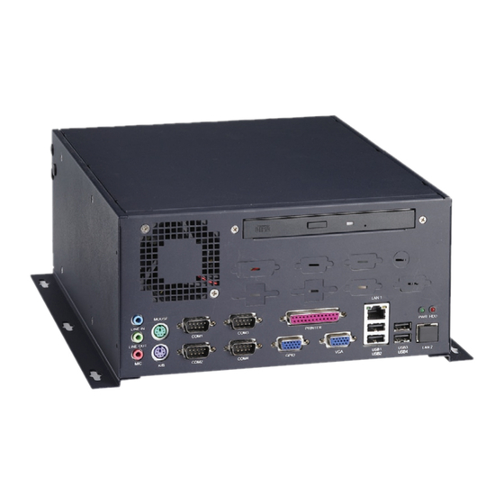
Page 32: The Front Plate
S-Video and a C-Video port for the optional display module kit. The momen- tary ATX power switch is placed on the rear side to prevent it from being touched by accident. Figure 4.2 Rear plate EBPC-5250 User Manual... -
Page 33: Replacing The Cooling Fan
Return the fan module with the wire facing downward to the chassis and fasten it to the four screws. Plug in the fan power connector. Replace the top cover and fasten it. Figure 4.3 Replacing the system fan EBPC-5250 User Manual... -
Page 34: Replacing The Power Supply
Replacing the Power Supply The EBPC-5250 supports a single power supply. To replace the power supply, pro- ceed as follows: Unplug the power cord from the power supply. Remove the top cover. Unplug the 12-pin ATX power connector from the SBC, as well as the power connectors from the disk drives and fan. -
Page 35: Exploded Diagram And Parts
Appendix Exploded Diagram and Parts List This appendix shows the exploded diagram and parts list of the EBPC-5250. -
Page 36: Exploded Diagram And Parts List
11. Slim optical disk drive front cover 3.I/O board 12.Slim optical disk drive bracket 4.Adapter bracket 13.Power supply bracket 5.HDD bracket 14.Chassis 6.Rubber cushion 15.Power supply 7.Fan guard 16.Riser card bracket 8. Fan module 17.Rear window 9.Mounting bracket EBPC-5250 User Manual... -
Page 37: Biscuit Sbc Options
Appendix 5.25" Biscuit SBC Options This appendix shows the 5.25" SBC options. -
Page 38: Biscuit Sbc Options
5.25" Biscuit SBC Options EBPC-5250 supports a variety of Advantech 5.25” biscuit SBCs (listed below). Users can contact a local sales representative for detailed information. Table B.1: 5.25" Biscuit SBC Options Model Slot Name Mini PCI PC/104 PC/104+ PCI-104 PCM-9581... - Page 39 EBPC-5250 User Manual...
- Page 40 No part of this publication may be reproduced in any form or by any means, electronic, photocopying, recording or otherwise, without prior written permis- sion of the publisher. All brand and product names are trademarks or registered trademarks of their respective companies. © Advantech Co., Ltd. 2008...
- Page 41 Компания «ЭлектроПласт» предлагает заключение долгосрочных отношений при поставках импортных электронных компонентов на взаимовыгодных условиях! Наши преимущества: Оперативные поставки широкого спектра электронных компонентов отечественного и импортного производства напрямую от производителей и с крупнейших мировых складов; Поставка более 17-ти миллионов наименований электронных компонентов; ...
Need help?
Do you have a question about the EBPC-5250 and is the answer not in the manual?
Questions and answers