Table of Contents
Advertisement
Quick Links
Advertisement
Table of Contents

Related Manuals for Advantech ECU-4553 Series


Summary of Contents for Advantech ECU-4553 Series
- Page 1 User Manual ECU-4553 Series (2021 Model) Hardware User Manual...
- Page 2 No part of this manual may be reproduced, copied, translated or transmitted in any form or by any means without the prior written permission of Advantech Co., Ltd. Information provided in this manual is intended to be accurate and reliable. How- ever, Advantech Co., Ltd.
- Page 3 Because of Advantech’s high quality-control standards and rigorous testing, most of our customers never need to use our repair service. If an Advantech product is defec- tive, it will be repaired or replaced at no charge during the warranty period. For out- of-warranty repairs, you will be billed according to the cost of replacement materials, service time and freight.
- Page 4 This product has passed the CE test for environmental specifications when shielded cables are used for external wiring. We recommend the use of shielded cables. This kind of cable is available from Advantech. Please contact your local supplier for ordering information.
- Page 5 The sound pressure level at the operator's position according to IEC 704-1:1982 is no more than 70 dB (A). DISCLAIMER: This set of instructions is given according to IEC 704-1. Advantech disclaims all responsibility for the accuracy of any statements contained herein.
- Page 6 Don't touch any components on the CPU card or other cards while the PC is on. Disconnect power before making any configuration changes. The sudden rush of power as you connect a jumper or install a card may damage sensitive elec- tronic components. ECU-4553 Series User Manual...
-
Page 7: Table Of Contents
System Software................2 1.2.4 I/O Interface .................. 2 1.2.5 Environment.................. 3 Safety Precautions ..................3 Chassis Dimensions.................. 4 Figure 1.1 ECU-4553 Series chassis dimensions ....... 4 Packing List....................5 Chapter Hardware Function ......7 Overview ....................8 Figure 2.1 ECU-4553 overview............ 8 LED Status Indicator ................. - Page 8 ECU-4553 Series User Manual viii...
-
Page 9: Chapter 1 Introduction
Chapter Introduction... -
Page 10: Product Concepts And Positioning
Product Concepts and Positioning ECU-4553 Series is a RISC architecture platform with high performance, wide tem- perature and flexible design. It serves as a gateway connecting inverters and remote monitoring center in power and energy application, which plays an important role. -
Page 11: Environment
Place all electronic components on a static-dissipative surface or in a static-shielded bag. Note! If DC voltage is supplied by an external circuit, please put a protection device in the power supply input port. ECU-4553 Series User Manual... -
Page 12: Chassis Dimensions
Chassis Dimensions Figure 1.1 ECU-4553 Series chassis dimensions ECU-4553 Series User Manual... -
Page 13: Packing List
Packing List The accessory package of ECU-4553 Series contains the following items: ECU-4553-LR21SBE (A) ECU-4553-LR21SBE (B) 1 x PLUG-IN BLOCK 3P (C) 4 x PLUG-IN BLOCK 20P (D) 16 x MINI JUMPER 2P 2.0mm (E) 1 x ROHS card (F) 1 x warranty card... - Page 14 ECU-4553 Series User Manual...
-
Page 15: Chapter 2 Hardware Function
Chapter Hardware Function... -
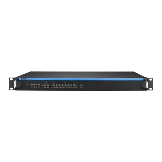
Page 16: Overview
Figure 2.2 ECU-4553 LED status indicator 2.2.1 System Status Indicator Status Description Green power is on PWR1 power is off Green power is on PWR2 power is off Green Customers can define the Programmable LED state according to the actual need. ECU-4553 Series User Manual... -
Page 17: Serial Communication Status Indicator
TX15 Orange Blinking, Serial port 15 data being transmitted RX15 Green Blinking, Serial port 15 data being received TX16 Orange Blinking, Serial port 16 data being transmitted RX16 Green Blinking, Serial port 16 data being received ECU-4553 Series User Manual... -
Page 18: Ethernet Status Indicator
CAN Status Indicator Color Description Orange Blinking, Serial port 1 data being transmitted Green Blinking, Serial port 1 data being received Orange Blinking, Serial port 2 data being transmitted Green Blinking, Serial port 2 data being received ECU-4553 Series User Manual... -
Page 19: Chapter 3 Wiring And Installation
Chapter Wiring and Installation... -
Page 20: Wiring
PWR1 N/PWR2 N AC power input PIN Power Input 3.1.2 Communication Ports Table 3.2: Power Loss Alarm Wiring Pin Definition Function Screen Printing Function Description Normal Connected Relay1 Normal Open Common Normal Connected Relay2 Normal Open Common ECU-4553 Series User Manual... -
Page 21: Communication Ports
Communication Ports 3.1.3.1 Debug Ports (COM1~COM2) Table 3.3: Debug Port Pin Definitions Pins RS-232 3.1.3.2 RS-232/485 Serial Ports (COM1~ COM16) Table 3.4: RS-232/485 Serial Ports (Pin Assignments) RS-232 RS-485 Data+ Data- IRIG IRIG+ IRIG- (Only COM1) ECU-4553 Series User Manual... - Page 22 3.1.3.3 USB Connector Table 3.5: USB Connector Pin Assignment Signal Cable Color DATA- White DATA+ Green Black Default: UART-MODE 3.1.3.4 LAN Connectors (LAN1~LAN4) Table 3.6: LAN Connector Pin Assignments Assignment Description Transmit+ Transmit- Receive+ Not used ECU-4553 Series User Manual...
- Page 23 3.1.3.5 VGA Display Connector Table 3.7: VGA Adaptor Cable Pin Assignments Assignment GREEN BLUE 3.1.3.6 Can Ports (CAN 1~2) Table 3.8: RS-232/485 Serial Ports (Pin Assignments) Pins CAN1 CANH CANL CAN2 CANH CANL ECU-4553 Series User Manual...
-
Page 24: Jumper Setting
CN67 CN53 CN64 Add 120 ohm terminal resistor on Data+/Data- of RS-485 CN66 CN51 CN80 CN81 CN84 CN82 CN92 CN94 Add 300 ohm terminal resistor on Data+/Data- of RS-485 CN96 CN93 CN95 CN97 COM16 Default: Empty ECU-4553 Series User Manual... -
Page 25: Installation
Add 300 ohm terminal resistor on Data+/Data- of CN3/CN4 Default: Empty Installation 3.3.1 Rack-mounted ECU-4553 provides the kits for rack mounting in the chassis. Use the 4 screw holes to mount the ECU-4553 on the rack. ECU-4553 Series User Manual... - Page 26 No part of this publication may be reproduced in any form or by any means, electronic, photocopying, recording or otherwise, without prior written permis- sion of the publisher. All brand and product names are trademarks or registered trademarks of their respective companies. © Advantech Co., Ltd. 2021...
Need help?
Do you have a question about the ECU-4553 Series and is the answer not in the manual?
Questions and answers