Table of Contents
Advertisement
Quick Links
Advertisement
Table of Contents

Related Manuals for Advantech EI-52


Summary of Contents for Advantech EI-52
- Page 1 User Manual EI-52 Fanless Edge Intelligence System...
- Page 2 This product contains a hard copy of the Chinese user manual for China CCC certification purposes. A PDF of the English user manual is included on the accompanying CD. Please disregard the hard copy Chinese user manual if the product is not sold and/or installed in China. EI-52 User Manual...
- Page 3 The documentation and the software included with this product are copyrighted 2021 by Advantech Co., Ltd. All rights are reserved. Advantech Co., Ltd. reserves the right to improve the products described in this manual at any time without notice. No part of this manual may be reproduced, copied, translated, or transmitted in any form or by any means without the prior written permission of Advantech Co., Ltd.
- Page 4 Product Warranty (2 Years) Advantech warrants the original purchaser that all of its products will be free from defects in materials and workmanship for two years from the date of purchase. This warranty does not apply to any products that have been repaired or altered by persons other than repair personnel authorized by Advantech, or products that have been subject to misuse, abuse, accident, or improper installation.
- Page 5 Technical Support and Assistance Visit the Advantech website at www.advantech.com/support to obtain the latest product information. Contact your distributor, sales representative, or Advantech's customer service center for technical support if you need additional assistance. Please have the following information ready before calling: –...
- Page 6 70 dB (A). The equipment should only be installed in a restricted access area. DISCLAIMER: These instructions are provided according to IEC 704-1 specifi- cations. Advantech disclaims all responsibility for the accuracy of any state- ments contained herein. EI-52 User Manual...
- Page 7 FSP/ FSP060-DAAN2) suitable for use at TMA 60 °C (140 °F) min., and the out- put is rated 24 V , 2.5A min., ES1. If you need further assistance, contact Advantech for additional information. Consignes de Sécurité Veuillez lire attentivement ces instructions de sécurité.
- Page 8 L'équipement ne doit être installé que dans une zone d'accès restreint. AVERTISSEMENT: Cet ensemble d'instructions est donné conformément à la norme CEI 704-1. Advantech décline toute responsabilité quant à l'exactitude des déclarations contenues dans ce. Ce modèle est destiné à être alimenté par une alimentation certifiée UL (adapta- teur: FSP / FSP060-DAAN2), adaptée à...
- Page 9 AMK-A0038 VEGA-330 and thermal kit for EI-52 (including VEGA-330 module and thermal solution) AMK-A0039 Thermal solution and Antenna for EI-52+AIW-355 5G module. (AIW-355 module is not included in AMK-A0039 and need to be ordered separately.) AMK-A0040 VESA and DIN-Rail Mounting kit for EI-52 AMO-I026A MiniPCIe to M.2, support M.2 Key B USB signal module (for using...
- Page 10 EI-52 User Manual...
-
Page 11: Table Of Contents
Ethernet ..................3 Chipset ...................... 3 1.3.1 Functional Specifications .............. 3 Mechanical Specifications................. 4 1.4.1 System Dimensions ..............4 Figure 1.1 EI-52 Mechanical Dimensions ........4 1.4.2 Weight................... 4 Power Requirements................. 5 1.5.1 System Power................5 1.5.2 RTC Battery .................. 5 Environmental Specifications .............. - Page 12 2.5.1 M.2 Installation................15 2.5.2 Mini PCIe Installation ..............17 2.5.3 EI-52 Wall Mount ................ 18 2.5.4 EI-52 DIN-Rail and VESA Mount (Optional AMK-A0040)... 18 Chapter BIOS Settings ........19 Introduction ..................... 20 Entering BIOS Setup................21 3.2.1 Main Setup.................. 21 3.2.2...
-
Page 13: Chapter 1 General Introduction
Chapter General Introduction This chapter gives background information on the EI-52 series... -
Page 14: Introduction
Intel OpenVINO toolkit. HDMI+DP Dual Display & Compact-size with Multiple I/Os EI-52 is fanless design, built-in DDR4 memory and SATA Slim SSD, and supports - 10 ~ 50°C operating temperature. The system dimensions is 156 x 112 x 60 mm compact size but with multiple I/Os, including 2 x RS-232/422/485, 2 x GbE, 6 x USB and support M.2 2280 M key and full-size mini PCIe expansions. -
Page 15: Display
If it is necessary for the LAN order recognized by OS and the LAN order printed on I/ O plate to be exactly the same, please do not order EI-52 207 OS image. To make the LAN order be the same for OS and physical connector printed on I/O plate, please follow the instructions in Appendix "Fixing the LAN order"... -
Page 16: Mechanical Specifications
Supports Line Out and Mic In audio Connectors: 1 x Earphone jack Battery 1 x 3V/210 mAh battery with wire Mechanical Specifications 1.4.1 System Dimensions 156 x 112 x 60 mm Figure 1.1 EI-52 Mechanical Dimensions 1.4.2 Weight 0.94 Kg EI-52 User Manual... -
Page 17: Power Requirements
1.6.5 Shock Tolerance When the system is equipped with an SSD/mSATA: 30 G, IEC 60068-2-27, half sine, 11 ms duration 1.6.6 Safety Certification UL, CB, CCC, BSMI 1.6.7 EMC Certification CE, FCC, CCC, BSMI EI-52 User Manual... - Page 18 EI-52 User Manual...
-
Page 19: Chapter 2 Hardware Installation
Chapter Hardware Installation This chapter details instructions for installing EI-52 hardware and external I/O... -
Page 20: Introduction
2.2.1 Jumper Description EI-52 can be configured to satisfy specific application requirements by setting jump- ers. A jumper is a metal bridge used to close an electric circuit. It consists of two metal pins and a small metal clip (often protected by a plastic cover) that slides over the pins to connect them. -
Page 21: Jumper Location
PIN HEADER 3x1P 2.0mm 180D(M) DIP 2000-13 WS Jumper Setting (1-8) OFF: RS485 RS422 Fail Safe Off Jumper Setting (2-7) OFF: RS485 RS422 Fail Safe Off Jumper Setting (3-6) OFF: RS485 RS422 Fail Safe Off Jumper Setting (4-5) OFF: RS485 RS422 Fail Safe Off EI-52 User Manual... -
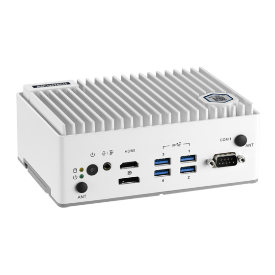
Page 22: System I/O
(1-8) OFF: RS485/RS422 Fail Safe Enabled Disabled Jumper Setting (2-7) OFF: RS485/RS422 Fail Safe Enabled Disabled Jumper Setting (3-6) OFF: RS485/RS422 Fail Safe Enabled Disabled Jumper Setting (4-5) OFF: RS485/RS422 Fail Safe Enabled Disabled System I/O Front View Rear View EI-52 User Manual... -
Page 23: External I/O
External I/O 2.4.1 Power On/Off Button EI-52 features a Power On/Off button with an LED indicators on the top side that show On status (Green LED) Figure 2.1 Power On/Off Button 2.4.2 Power Input Connector The power input connector supports DC in 19V. -
Page 24: Usb 3.0 Connector
USB0_SSTX- USB0_SSTX+ 2.4.5 Audio Connector EI-52 features one phone jack connectors that support stereo Line Out and Mic In audio ports. The audio chip is controlled by ALC888S and compliant with the Azalea standard. Figure 2.4 Audio Connector Table 2.6: Audio Connector Pin Definition... -
Page 25: Com Connector
RS-485 DATA- DATA+ NC represents “No Connection”. 2.4.7 DP Connector EI-52 offers one DP interface. The DP interface supports resolution up to 7680x4320. Table 2.8: DP Connector Pin Definition Signal Name Signal Name ML_Lane 0 (p) ML_Lane 0 (n) ML_Lane 1 (p) -
Page 26: Hdmi Connector
2.4.8 HDMI Connector EI-52 offers two integrated 19-pin receptacle connector HDMI 2.0b interfaces. The HDMI link supports resolutions up to 4096 x 2304 @ 60 Hz. Figure 2.6 HDMI Connector Table 2.9: HDMI Connector Pin Definition... -
Page 27: Installation
Installation 2.5.1 M.2 Installation Loosen the 4 screws affixing screws and remove the bottom cover. Loosen the 4 screws and remove the mechanical plate for storage. Install the M.2 2280 M key module. EI-52 User Manual... - Page 28 Reinstall the mechanical plate for storage and bottom cover and secure it with screws (each 4x screws). EI-52 User Manual...
-
Page 29: Mini Pcie Installation
2.5.2 Mini PCIe Installation Loosen the 4 screws affixing screws and remove the bottom cover. Loosen the 4 screws and remove the mechanical plate for storage. Install full-size mini PCIe module. EI-52 User Manual... -
Page 30: Ei-52 Wall Mount
2.5.3 EI-52 Wall Mount EI-52 default supports wall mount with the two wings on the bottom cover. 2.5.4 EI-52 DIN-Rail and VESA Mount (Optional AMK-A0040) EI-52 default supports optional DIN-Rail and VESA mount with optional AMK-A0040 mounting kit. EI-52 User Manual... -
Page 31: Bios Settings
Chapter BIOS Settings This chapter details the BIOS con- figuration instructions... -
Page 32: Introduction
All configuration data is stored in battery-backed CMOS to ensure the setup information is retained when the power is turned off. This chapter describes the basic navigation of the EI-52 BIOS setup screens EI-52 User Manual... -
Page 33: Entering Bios Setup
System Date using the <Arrow> keys. Enter new values via the keyboard. Press the <Tab> key or the <Arrow> keys to move between fields. The date must be entered in MM/DD/YY format, and the time must be entered in HH:MM:SS for- mat. EI-52 User Manual... -
Page 34: Advanced Bios Setup
Setup page. Select any of the items in the left frame of the screen, such as CPU Con- figuration, to access the sub menu for that item. The options for any of the Advanced BIOS Setup items can be displayed by highlighting the item using the <Arrow> keys. 3.2.2.1 CPU Configuration EI-52 User Manual... - Page 35 It is a one time only change, next reboot will be reset. DPR Memory Size (MB) Reserve DPR memory size (0-255) MB Reset AUX Content Reset TPM Aux content. Txt may not functional after AUX content gets reset. 3.2.2.2 Power & Performance EI-52 User Manual...
- Page 36 GT - Power Management Control RC6(Render Standby) Check to enable render standby support. Maximum GT frequency Maximum GT frequency limited by the user. Disable Turbo GT frequency Enabled: Disables Turbo GT frequency. Disabled: GT frequency is not limited EI-52 User Manual...
- Page 37 3.2.2.3 PCH-FW Configuration EI-52 User Manual...
- Page 38 ME State When Disabled ME will be put into ME Temporarily Disabled Mode. Manageability Features State Enable/Disable Intel(R) Manageability features. EI-52 User Manual...
- Page 39 Hide Unconfigure ME Confirmation Prompt Hide Unconfigure ME confirmation prompt when attempting ME unconfigura- tion. MEBx OEM Debug Menu Enable Enable OEM debug menu in MEBx. Unconfigure ME Unconfigure ME with resetting MEBx password to default. EI-52 User Manual...
- Page 40 ACPI Settings Enable ACPI Auto Configuration Enables or Disables BIOS ACPI Auto Configuration. Enable Hibernation nables or Disables System ability to Hibernate (OS/S4 Sleep State). This option may not be effective with some operating systems. EI-52 User Manual...
- Page 41 ACPI Sleep State Select the highest ACPI sleep state the system will enter when the SUSPEND button is pressed. S3 Video Repost Enable or Disable S3 Video Repost. 3.2.2.5 iManager Configuration EI-52 User Manual...
- Page 42 COM2 Mode COM2 mode select. Hardware Monitor Provide hardware monitor information Watch Dog Timer Configuration Watch Dog Timer Enabled or Disabled Watch Dog Timer function (Start before boot to OS and must stop by self) EI-52 User Manual...
- Page 43 3.2.2.6 Trusted Computing Security Device Support Enables or Disables BIOS support for security device. SHA-1 PCR Bank Enable or Disable SHA-1 PCR Bank. EI-52 User Manual...
- Page 44 SHA256 PCR Bank Enable or Disable SHA256 PCR Bank. Pending operation Schedule an Operation for the security device. EI-52 User Manual...
- Page 45 3.2.2.7 S5 RTC Wake Settings Wake System from S5 Enable or disable System wake on alarm event. When enabled, System will wake on the hr::min::sec specified EI-52 User Manual...
- Page 46 3.2.2.8 Serial Port Console Redirection Console Redirection Console Redirection Enable or Disable. EI-52 User Manual...
- Page 47 3.2.2.9 Intel TXT Information Provide Intel TXT information. EI-52 User Manual...
- Page 48 3.2.2.10 USB Configuration Legacy USB Support Enables Legacy USB support. XHCI Hand-Off This is a workaround for OSes without XHCI hand-off support. USB Mass Storage Driver Support: Enable/Disable USB Mass Storage Driver Support. EI-52 User Manual...
- Page 49 The time-out value for Control, Bulk, and Interrupt transfers. Device Reset Timeout USB mass storage device Start Unit command time-out. Device Power-Up Delay Maximum time the device will take before it properly reports itself to the Host Controller. EI-52 User Manual...
- Page 50 3.2.2.11 Network Stack Configuration Network Stack Enable/Disable UEFI network stack. EI-52 User Manual...
- Page 51 3.2.2.12 CSM Configuration CSM Support Enable/Disable CSM support. EI-52 User Manual...
-
Page 52: Chipset Configuration
3.2.3.1 System Agent (SA) Configuration Memory Configuration Display memory information. VT-d VT-d capability. Above 4GB MMIO BIOS assignment Enable/Disable above 4GB MemoryMappedIO BIOS assignment. This is enabled automatically when Aperture Size is set to 2048MB. EI-52 User Manual... - Page 53 EI-52 User Manual...
- Page 54 3.2.3.2 PCH-IO Configuration EI-52 User Manual...
- Page 55 PCI Express Configuration M.2 E Key Select to enable or disable M.2 E Key. EI-52 User Manual...
- Page 56 Aggressive LPM Support Enable PCH to aggressively enter link power state. Port 1 Enable or disable SATA port. SATA Device Type Identify the SATA port is connected to Solid State Drive or Hard Disk Drive EI-52 User Manual...
- Page 57 USB Configuration xDCI Support Enable/Disable xDCI (USB OTG Device). USB2 PHY Sus Well Power Gating Select 'Enabled' to enable SUS Well PG for USB2 PHY. EI-52 User Manual...
- Page 58 Select 'Enabled' if Overcurrent functionality is used. Enabling this will make xHCI controller consume the Overcurrent mapping data. USB Port Disable Override Selectively Enable/Disable the corresponding USB port from reporting a Device Connection to the controller. EI-52 User Manual...
- Page 59 RTC Memory Lock Enable will lock bytes 38h-3Fh in the lower/upper 128-byte bank of RTC RAM. BIOS Lock Enable/Disable the PCH BIOS Lock Enable feature. Required to be enabled to ensure SMM protection of flash. EI-52 User Manual...
- Page 60 Enable or disable boot option for LAN2 Controller. PCIE Wake Enable or disable PCIE to wake the system from S5. Restore AC Power Loss Specify what state to go to when power is re-applied after a power failure (G3 state) EI-52 User Manual...
-
Page 61: Security
3.2.4 Security Security Administrator Password Set Administrator Password. User Password Set User Password. EI-52 User Manual... -
Page 62: Boot
Policy variables can be configured by a physically present user without full authentication. 3.2.5 Boot Boot Setup Prompt Timeout Number of seconds to wait for setup activation key. Bootup NumLock State Select the keyboard NumLock state. Quiet Boot Enables or disables Quiet Boot option. EI-52 User Manual... -
Page 63: Save & Exit
Restore Defaults Restore/Load Default values for all the setup options. Save as User Defaults Save the changes done so far as User Defaults. Restore User Defaults Restore the User Defaults to all the setup options. EI-52 User Manual... - Page 64 EI-52 User Manual...
-
Page 65: Appendix Alan Order Change Method
Appendix LAN Order Change Method... -
Page 66: Problem Statement
If it is necessary for the LAN order recognized by OS matches the LAN order of print- ing on I/O plate to be exactly the same, please do not order EI-52 207 OS image. To make the LAN order be the same, users need to order Windows 10 license key, install Windows 10 via iso file and follow the instructions in below “Addressing the... -
Page 67: Addressing The Lan Order
Configuration → Onboard LAN2 controller → [Disabled]). Figure A.4 Before installing I219 LAN driver, there is no any LAN adapter shown in device manager. Figure A.5 After installing I219 LAN driver, I219 will be recognized and shown in device manager. EI-52 User Manual... - Page 68 Figure A.6 Users should see that LAN 1 is I219, and LAN 2 is I210 in OS, which matches the printing on I/O plate as shown in Figure 1. EI-52 User Manual...
- Page 69 EI-52 User Manual...
- Page 70 No part of this publication may be reproduced in any form or by any means, such as electronically, by photocopying, recording, or otherwise, without prior written permission from the publisher. All brand and product names are trademarks or registered trademarks of their respective companies. © Advantech Co., Ltd. 2021...
Need help?
Do you have a question about the EI-52 and is the answer not in the manual?
Questions and answers