Table of Contents
Advertisement
Quick Links
Advertisement
Table of Contents

Related Manuals for Advantech EPC-S202


Summary of Contents for Advantech EPC-S202
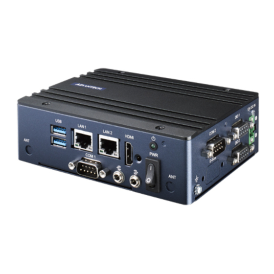
- Page 1 User Manual EPC-S202 Fanless Embedded PC...
- Page 2 English user manual included as a PDF file on the website. Please disregard the Chinese hard copy user manual if the product is not to be sold and/or installed in China. EPC-S202 User Manual...
- Page 3 The documentation and the software included with this product are copyrighted 2020 by Advantech Co., Ltd. All rights are reserved. Advantech Co., Ltd. reserves the right to make improvements in the products described in this manual at any time without notice.
- Page 4 Because of Advantech’s high quality-control standards and rigorous testing, most of our customers never need to use our repair service. If an Advantech product is defec- tive, it will be repaired or replaced at no charge during the warranty period. For out- of-warranty repairs, you will be billed according to the cost of replacement materials, service time and freight.
- Page 5 Technical Support and Assistance Visit the Advantech web site at www.advantech.com/support where you can find the latest information about the product. Contact your distributor, sales representative, or Advantech's customer service center for technical support if you need additional assistance. Please have the following information ready before you call: –...
- Page 6 Packing List Before installation, please ensure the following items have been shipped: 1 x EPC-S202 unit 1 x China RoHS Ordering Information Model Number Description EPC-S202E-U0A1 Intel E3950 2.0GHz EPC, 12VDC, VGA, DIO, 2 COM port EPC-S202E-S8A1 Intel E3930 1.8GHz EPC, 12VDC, VGA, DIO, 2 COM port...
- Page 7 GUARD (for example, in the case of some lithium BATTERY types). Disposal of a BATTERY into fire or a hot oven, or mechanically crushing or cutting of a BATTERY, that can result in an EXPLOSION. EPC-S202 User Manual...
- Page 8 L'utilisateur. Si l'une des situations suivantes se présente, faites vérifier l'équipement par le personnel de service: Le cordon d'alimentation ou la fiche est endommagé. Le liquide a pénétré dans l'équipement. EPC-S202 User Manual viii...
- Page 9 645 du Code national de l'électricité et à la norme NFPA 75. AVIS DE NON-RESPONSABILITÉ: Cet ensemble d'instructions est conforme à la norme CEI 704-1. Advantech décline toute responsabilité concernant l'exacti- tude des déclarations contenues dans ce document. EPC-S202 User Manual...
- Page 10 EPC-S202 User Manual...
-
Page 11: Table Of Contents
1.3.1 Functional Specification ..............3 1.3.2 WISE-PaaS/DeviceOn ..............3 Mechanical Specifications................. 4 1.4.1 EPC-S202 Dimensions ..............4 Figure 1.1 EPC-S202 Mechanical Dimensions Diagram ..... 4 1.4.2 Weight................... 4 Power Requirements................. 4 1.5.1 System Power................4 1.5.2 RTC Battery .................. 4 Environment Specifications............... - Page 12 Save & Exit ................. 41 Appendix A Watchdog Timer Sample Code ..43 Watchdog Timer Sample Code............... 44 Appendix B SUSI API Introduction....... 47 SUSI API Introduction ................48 B.1.1 The Watchdog API..............48 B.1.2 The Hardware Monitor API ............48 EPC-S202 User Manual...
-
Page 13: Chapter 1 General Introduction
Chapter General Introduction This chapter details background information on the EPC-S202 series. -
Page 14: Introduction
EPC-S202 is powered by an Intel® Atom™ E3950/E3930 to deliver high perfor- mance with low power consumption. EPC-S202 supports up to 2x COM port, 2x USB 3.0, 2x GbE LAN, one M.2 E key, mSATA/mPCIe, and on-board 4 GB LPDDR4 mem- ory and 32 GB eMMC storage for rugged environments. -
Page 15: Chipset
BATTERY 3V/210 mAh with WIRE x 1 1.3.2 WISE-PaaS/DeviceOn Sequence control Supported Watchdog timer 65536 level, 0~65535 sec Hardware monitor CPU temperature / input current / input voltage Power saving Deep sleep S5 mode System information Running HR / boot record EPC-S202 User Manual... -
Page 16: Mechanical Specifications
Mechanical Specifications 1.4.1 EPC-S202 Dimensions 139 x 100 x 44 mm (5.47 x 3.93 x 1.73 in) Unit: mm [Inch] Figure 1.1 EPC-S202 Mechanical Dimensions Diagram 1.4.2 Weight 0.6 kg (1.32 lb) Power Requirements 1.5.1 System Power Minimum power input: DC 12 V, 5 A ... -
Page 17: Environment Specifications
Desk/Wall Mount/ DIN Rail: 3 Grms, IEC 60068-2-64, random vibration, 5 ~ 500 Hz, 1 hr/axis 1.6.5 Shock during Operation 30G, IEC60068-2-27, half sine, 11 m duration 1.6.6 Safety UL, CB, CCC, BSMI 1.6.7 CE, FCC, CCC, BSMI, VCCI EPC-S202 User Manual... - Page 18 EPC-S202 User Manual...
-
Page 19: Chapter 2 H/W Installation
Chapter H/W Installation This chapter details external I/O and EPC-S202 hardware installa- tion. -
Page 20: Introduction
Introduction The following sections demonstrate the installation and the external connector pin assignments for different applications. I/O Introduction Figure 2.1 EPC-S202 Front View Figure 2.2 EPC-S202 Rear View EPC-S202 User Manual... -
Page 21: Epc-S202 External I/O
EPC-S202 External I/O 2.3.1 Power On/Off Button EPC-S202 has a Power On/Off switch button on the front side that show On status (I) and Off/Suspend status (O). Figure 2.3 Power On/Off Button 2.3.2 Power Input Connector EPC-S202 is designed with a phoenix connector and 12 DC input. (-) stands for GND;... -
Page 22: Usb 3.0 Connector
2.3.4 USB 3.0 Connector EPC-S202 supports two USB interfaces, which deliver Plug & Play and hot swapping capabilites for up to 127 external devices. The USB interface complies with USB UHCI, Rev. 3.0. Please refer to Table. 2.2 for its pin assignments. USB 3.0 connectors contain legacy pins to interface to USB 2.0 devices, and a new set of pins for USB 3.0 connectivity... -
Page 23: Com Connector
2.3.6 COM Connector EPC-S202 provides two serial ports in D-sub 9-pin connectors. COM1/COM2 is for RS232/422/485 functionality. It provides connections for serial devices or a communi- cation network. Figure 2.8 COM Connector Table 2.4: COM Connector Pin Definition RS-232 RS-422... -
Page 24: Hdmi Connector
2.3.7 HDMI Connector EPC-S202 supports a HDMI port. This is a 19-pin receptacle connector HDMI 1.4b interface. This HDMI link supports resolutions of up to 3840 x 2160 @ 30 Hz. Figure 2.9 HDMI Connector Table 2.5: HDMI Connector Pin Definition... -
Page 25: Power Led Indicators
2.3.8 Power LED Indicators EPC-S202 provides one front panel LED that indicates power statuses. Figure 2.10 Power LED Indicators 2.3.9 Antenna Hole EPC-S202 reserves two antenna holes for wireless antenna installation. Each antenna hole is marked “ANT” for easy recognition. -
Page 26: Installation
Replace the bottom cover and secure it with the four screws. Desserrez les vis et ouvrez le bas du boîtier. Installez le module M.2 ou miniPCIe. Remettez le couvercle du boîtier inférieur et fixez-le avec les quatre vis. EPC-S202 User Manual... -
Page 27: Bios Settings
Chapter BIOS Settings... - Page 28 AMIBIOS has been integrated into motherboards for decades. With the AMIBIOS Setup program, you can modify BIOS settings and control various system features. This chapter describes the basic navigation of the EPC-S202 BIOS setup screens. AMI BIOS ROM has a built-in Setup program that allows users to modify basic sys- tem configurations.
-
Page 29: Entering Setup
BIOS supports your CPU. If there is no number assigned to the patch code, please contact an Advantech application engineer to obtain an up-to-date patch code file. This will ensure that your CPU‘s system status is valid. -
Page 30: Advanced Bios Features Setup
3.1.2 Advanced BIOS Features Setup Select the Advanced tab from the EPC-S202 setup screen to enter the Advanced BIOS Setup screen. You can select any of the items in the left frame of the screen, such as CPU Configuration, to go to the sub menu for that item. You can display an Advanced BIOS Setup option by highlighting it using the <Arrow>... - Page 31 3.1.2.1 Driver Health Provide Health Status for the Drivers/Controllers. EPC-S202 User Manual...
- Page 32 Physical Presence Spec Version Select to Tell O.S. to support PPI Spec Version 1.2 or 1.3. Device Select TPM 1.2 will restrict support to TPM 1.2 devices, TPM 2.0 will restrict support to TPM 2.0 devices. EPC-S202 User Manual...
- Page 33 Serial Port 1 Configuration Set Parameters of Serial Port 1 (COMA). Serial Port 2 Configuration Set Parameters of Serial Port 2 (COMB). Hardware Monitor Monitor hardware status. Watch Dog Timer Configuration Watch Dog Timer Configuration Page. EPC-S202 User Manual...
- Page 34 Serial Port Console Redirection Console Redirection This item allows users to enable or disable console redirection for Microsoft Windows Emergency Management Services (EMS). Console Redirection This item allows users to configure console redirection detail settings. EPC-S202 User Manual...
- Page 35 CPU Configuration Intel Virtualization Technology When enabled, a VMM can utilize the additional hardware capabilities provided by Vanderpool Technology. VT-d Enable/Disable CPU VT-d. Monitor Mwait Enable/Disable Monitor Mwait. P-STATE Coordination Change P-STATE Coordination type. EPC-S202 User Manual...
- Page 36 3.1.2.6 Network Stack Configuration Network Stack Enable/Disable UEFI Network Stack. EPC-S202 User Manual...
- Page 37 Controls the execution of UEFI and Legacy Storage OpROM. Video Controls the execution of UEFI and Legacy Video OpROM. Other PCI devices Determines OpROM execution policy for devices other than Network, Storage, or Video. EPC-S202 User Manual...
- Page 38 3.1.2.8 SDIO Configuration SDIO Access Mode Select SDIO device operating mode to DMA or PIO mode. EPC-S202 User Manual...
- Page 39 Maximum time the device will take before it properly reports itself to the Host Controller. 'Auto' uses default value: for a Root port it is 100 ms, for a Hub port the delay is taken from Hub descriptor. EPC-S202 User Manual...
- Page 40 3.1.2.10 Security Configuration TXE HMRFPO Disable TXE EOP Message Send EOP Message Before Enter OS. EPC-S202 User Manual...
-
Page 41: Chipset Configuration
3.1.3 Chipset Configuration North Bridge Details for North Bridge items. South Bridge Details for South Bridge items. Uncore Configuration Details for Uncore Configuration. South Cluster Configuration Details for South Cluster Configuration. EPC-S202 User Manual... - Page 42 3.1.3.1 North Bridge Max TOLUD Maximum Value of TOLUD. EPC-S202 User Manual...
- Page 43 3.1.3.2 South Bridge Serial IRQ Mode Configure Serial IRQ Mode. SMBus Support Enable/Disable SMBus Support. OS Selection Select the target OS. EPC-S202 User Manual...
- Page 44 Select DVMT 5.0 Total Graphic Memory size used by the Internal Graphics Device. Cd Clock Frequency Select the highest Cd Clock frequency supported by the platform. GT PM Support Enable/Disable GT PM Support. PAVP Enable Enable/Disable PAVP. Memory Scrambler Enable/Disable Memory Scrambler support. EPC-S202 User Manual...
- Page 45 3.1.3.4 South Cluster Configuration HD-Audio Configuration HD-Audio Configuration Settings. PCI Express Configuration PCI Express Configuration Settings. SCC Configuration SCC Configuration Settings. USB Configuration USB Configuration Settings. Miscellaneous Configuration Enable/Disable Misc. Features. EPC-S202 User Manual...
- Page 46 HD-Audio Configuration HD-Audio Support Enable/Disable HD-Audio Support. EPC-S202 User Manual...
- Page 47 PCI Express Root Port 5 / 6 Control the PCI Express Root Port. Onboard LAN1/LAN2 Controller Select to Enable or Disable Onboard LAN1/LAN2 Controller. LAN Option ROM Enabled / Disabled Onboard LAN’s PXE option ROM. EPC-S202 User Manual...
- Page 48 SCC Configuration SCC eMMC Support (D28:F0) Enable/Disable SCC eMMC Support. eMMC Max Speed Select the eMMC max Speed allowed. EPC-S202 User Manual...
- Page 49 Selectively Enable/Disable corresponding USB port from reporting a Device Connection to the controller. XHCI Disable Compliance Mode Options to disable XHCI Link Compliance Mode. USB HW MODE AFE Comparators Enable/Disable USB HW MODE AFE Comparators. EPC-S202 User Manual...
- Page 50 BIOS Lock Enable/Disable the BIOS Lock Enable feature. RTC Lock Enable or disable bytes 38h-3Fh in the upper and lower 128-byte bank of RTC RAM lockdown. TCO SMI Lock Enable TCO and Lock Down TCO. EPC-S202 User Manual...
-
Page 51: Security
3.1.4 Security Select Security Setup from the EPC-S202 Setup main BIOS setup menu. All Security Setup options, such as password protection and virus protection are described in this section. To access the sub menu for the following items, select the item and press <Enter>:... -
Page 52: Boot
Enables or Disables boot with initialization of a minimal set of devices required to launch active boot option. Has no effect for BBS boot options. New Boot Option Policy Controls the placement of newly detected UEFI boot options. EPC-S202 User Manual... -
Page 53: Save & Exit
This item allows you to save the changes done so far as user defaults. Restore User Defaults This item allows you to restore the user defaults to all the options. Boot Override Boot device select can override your boot priority. EPC-S202 User Manual... - Page 54 EPC-S202 User Manual...
-
Page 55: Appendix A Watchdog Timer Sample Code
Appendix Watchdog Timer Sample Code... -
Page 56: Watchdog Timer Sample Code
;==================================================== ;66H ;WDT timer time-out value ;bit[7:0]=0~255 ;==================================================== mov dx,SCH3114_IO + 66h mov al,01h out dx,al ;==================================================== ;bit[0] status bit R/W ;WD timeout occurred =1;WD timer counting = 0 ;==================================================== mov dx,SCH3114_IO + 68h EPC-S202 User Manual... - Page 57 .exit EPC-S202 User Manual...
- Page 58 EPC-S202 User Manual...
-
Page 59: Susi Api
Appendix SUSI API Introduction... -
Page 60: Susi Api Introduction
Application programmers can invoke the functions exported by SUSI instead of call- ing the drivers directly. The benefit of using SUSI is portability. The same set of APIs is defined for different Advantech hardware platforms. Also, the same API set is implemented in different Operating Systems. This user's manual describes some sample programs and the API in SUSI. - Page 61 EPC-S202 User Manual...
- Page 62 No part of this publication may be reproduced in any form or by any means, electronic, photocopying, recording or otherwise, without prior written permis- sion from the publisher. All brand and product names are trademarks or registered trademarks of their respective companies. © Advantech Co., Ltd. 2020...
Need help?
Do you have a question about the EPC-S202 and is the answer not in the manual?
Questions and answers