Table of Contents
Advertisement
Quick Links
Advertisement
Table of Contents

Subscribe to Our Youtube Channel
Related Manuals for Advantech EIS-S232


Summary of Contents for Advantech EIS-S232
- Page 1 User Manual ARK-3532 Fanless Embedded Box PC...
- Page 2 Attention! Please note: This package contains a hard-copy user manual in Chinese for China CCC certifica- tion purposes. There is an English user manual included as a PDF file on the CD. Please disregard the Chinese hard copy user manual if the product is not to be sold and/or installed in China.
- Page 3 The documentation and the software included with this product are copyrighted 2021 by Advantech Co., Ltd. All rights are reserved. Advantech Co., Ltd. reserves the right to make improvements in the products described in this manual at any time without notice.
- Page 4 Because of Advantech’s high quality-control standards and rigorous testing, most of our customers never need to use our repair service. If an Advantech product is defec- tive, it will be repaired or replaced at no charge during the warranty period. For out- of-warranty repairs, you will be billed according to the cost of replacement materials, service time and freight.
- Page 5 Technical Support and Assistance Visit the Advantech website at www.advantech.com/support where you can find the latest information about the product. Contact your distributor, sales representative, or Advantech's customer service center for technical support if you need additional assistance. Please have the following information ready before you call: –...
- Page 6 Ordering Information Option 3rd 232/ MiniP DC I Expans Part No. DDR4 Gbe VGA HDMI SI M M.2 display 422/ 3.2+3.0 CI e* nout module LGA120 ARK-3532B- Up to 9-36V 0 Socket ex4+PC 00A1 64GB Type I ex16 LGA120 ARK- Up to 9-36V 0 Socket...
- Page 7 70 dB (A). The equipment should only be installed in -restricted access areas. DISCLAIMER: These instructions are provided according to IEC 704-1 specifi- cations. Advantech disclaims all responsibility for the accuracy of any statements con- tained herein. ARK-3532 User Manual...
- Page 8 This product is intended to be supplied by a UL Listed power supply suitable for use at minimum Tma 50 °C (122 °F) whose output meets PS2 (or LPS), ES1(or SELV) and output is rated: 9-36Vdc, 16.65-4.16A. Please contact Advantech for further information.
- Page 9 L'équipement ne doit être installé que dans une zone d'accès restreint. AVERTISSEMENT: Cet ensemble d'instructions est donné conformément à la norme CEI 704-1. Advantech décline toute responsabilité quant à l'exactitude des déclarations contenues dans ce. Au moyen d'un cordon d'alimentation connecté à une prise de courant avec mise à...
- Page 10 ARK-3532 User Manual...
-
Page 11: Table Of Contents
Contents Chapter General Introduction ......1 Introduction ....................2 Product Features..................3 1.2.1 General ..................3 1.2.2 Display ..................3 1.2.3 Ethernet ..................3 Chipset ...................... 4 1.3.1 Functional specifications............... 4 1.3.2 SUSI 4.0..................5 Mechanical Specifications................. 6 1.4.1 Dimensions ................... 6 1.4.2 Weight................... - Page 12 2.4.5 Paste the Thermal pad ............... 23 Chapter BIOS Settings ........25 Introduction ..................... 26 Entering the Setup .................. 27 3.2.1 Main Setup.................. 27 3.2.2 Advanced BIOS Features Setup..........28 3.2.3 Chipset Configuration ..............63 3.2.4 Security..................82 3.2.5 Boot .................... 84 3.2.6 Save &...
-
Page 13: Chapter 1 General Introduction
Chapter General Introduction This chapter details background information on the ARK-3532 series. -
Page 14: Introduction
485 and 2 x RS-232 COM ports. Built-in Intelligent Management Tools — Advantech SUSI API and WISE-Devi- ceOn Advantech SUSI API provides a valuable suite of programmable APIs such as multi- level watchdog, hardware monitoring, system restoration, and other user-friendly interfaces. -
Page 15: Product Features
– 1 x Full size MiniPCIe (support mSATA and 1 with SIM) – 1 x M.2 (E key for Wi-Fi, suggested installation at Advantech manufacturing) – Add-on Card Slot:3532B for 1 Slot PCIex4+ 1 Slot PCIex16, 3532C for 1 Slot PCIex4 + 2 Slot PCI,3532D for 1 Slot PCIex4 + 2 Slot PCI + 1 Slot PCIex16 TPM: TPM 2.0 (Optional) -
Page 16: Chipset
Chipset 1.3.1 Functional specifications 1.3.1.1 Processor Processor Supports 10th Gen. Intel® LGA1200 processor (up to 65W) Memory Supports DDR4 2933 MHz up to 64GB 2 x 260-pin SODIMM socket type 1.3.1.2 Chipset Internal Graphics Features Direct x 12, OpenGL 4.5 ... -
Page 17: Susi 4.0
SUSI API Sequence Control Supported DIO 16-bit programmable DIO Watchdog Timer Multi-level WDT (set by Advantech iManager) Programmable 1-255 sec / min Hardware Monitor CPU Temperature / input Current / input Voltage System Information Running HR / Boot record ... -
Page 18: Mechanical Specifications
Mechanical Specifications 1.4.1 Dimensions ARK-3532B/ARK-3532C (W x H x D) 156 x 204 x 230 mm/6.14 x 8.03 x 9.05 in ARK-3532 User Manual... -
Page 19: Weight
ARK-3532D (W x H x D) 197.2 x 204 x 230 mm/7.7 x 8.03 x 9.05 in 1.4.2 Weight ARK3532B/ARK3532C: 5.7 kg (12.5 lb) ARK3532D: 6.41 kg (14.1 lb) Power Requirements 1.5.1 System power Minimum Power Input: 9 ~ 36VDC ... -
Page 20: Operating Environment Specifications
Operating Environment Specifications 1.6.1 Operating temperature With extended peripherals: -20 ~ 60 °C (-4 ~ 140 °F) with 0.7m/s air flow 1.6.2 Relative humidity 95% @ 40 °C (104 °F) (non-condensing) 1.6.3 Storage temperature -40 ~ 85 °C (-40 ~ 185 °F) ... -
Page 21: Chapter 2 Hardware Configuration
Chapter Hardware Configuration... -
Page 22: Introduction
Introduction The following sections show the internal jumper settings and the external connector pin assignments for different applications. Jumpers 2.2.1 Jumper Description You may configure ARK-3532 to match the needs of your application by setting jump- ers. A jumper is a metal bridge used to close an electric circuit. It consists of two metal pins and a small metal clip (often protected by a plastic cover) that slides over the pins to connect them. -
Page 23: Jumper Locations
2.2.3 Jumper Locations Figure 2.1 Jumper Layout ARK-3532 User Manual... -
Page 24: Jumper Settings
2.2.4 Jumper Settings 2.2.4.1 Auto Power On Setting for J1 J1 Auto Power On Setting Part Number 1655303020 Footprint WHL3V-2M Description WAFER BOX 3P 2.0 mm 180D(M) DIP 2001-WS-3 Setting Function (1-2) Auto Power On (2-3) Power Button for Power On (Default) 2.2.4.2 Clear CMOS Setting for JCMOS1 JCMOS1 Clear CMOS Setting... - Page 25 2.2.4.4 PCIE X16 Lane reversal setting for J_CFG2 J_CFG2 PCIE X16 Lane reversal Setting Part Number 1653003101 Footprint HD_3x1P_79_D Description PIN HEADER 3x1P 2.0 mm 180D(M) DIP 2000-13 WS Setting Function (1-2) 0: Lane numbers reversed (Default) (2-3) 1: Normal operations 2.2.4.5 PCIE X16 Bifurcation setting for J_CFG5 and J_CFG6 J_CFG5 and J_CFG6 PCIE X16 Bifurcation Setting...
-
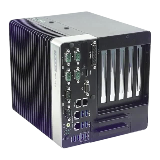
Page 26: Connectors
Connectors 2.3.1 ARK-3532 External I/O Locations Figure 2.2 ARK-3532 Front and Rear I/O Connector Diagram 2.3.1.1 COM Connector ARK-3532 provides up to 6 D-sub 9-pin connectors, which offers RS-232/422/485 serial communication interface ports. The default setting is RS-232, the mode RS-422/ 485 of ARK-3532 COM3/4/5/6 can be supported via the BIOS settings. - Page 27 Table 2.2: COM Connector Pin Assignments Note! NC represents “No Connection”. COM1~COM2 1 2 3 4 5 6 7 8 9 Table 2.3: COM Connector Pin Assignments RS-232 Signal Name 2.3.1.2 Ethernet Connector (LAN) ARK-3532 is equipped with up to 4 x (LAN3/4 are optional by TPN support) Ethernet controllers that are fully compliant with IEEE 802.3u 10/100/1000 Mbps CSMA/CD standards.
- Page 28 Table 2.4: Ethernet Connector Pin Assignments 10/100/1000BaseT Signal Name MDI2+ MDI2- MDI3+ MDI3- 2.3.1.3 HDMI Connector An integrated, 19-pin receptacle connector HDMI Type A Interface is provided. The HDMI link supports resolutions up to 3840 x 2160 @ 30 Hz. Figure 2.5 HDMI Receptacle Connector Table 2.5: HDMI Connector Pin Assignments Signal Name...
- Page 29 Table 2.6: VGA Connector Pin Assignments Signal Name Signal Name Green Blue DDAT H-SYNC V-SYNC DCLK 2.3.1.5 DIO Connector Figure 2.7 DIO Connector Table 2.7: DIO Connector Pin Assignment Signal Name Signal Name Port0 D0 Port1 D8 Port0 D1 Port1 D9 Port0 D2 Port1 D10 Port0 D3...
- Page 30 2.3.1.6 Power On/Off Button ARK-3532 has a Power On/Off button with LED indicators on the front side that show “On” (Green LED) and “Off/Suspend” statuses (Orange LED). The Power button sup- ports dual functions: Soft Power - On/Off (Instant off or Delay 4 Seconds then off), and Suspend.
-
Page 31: Installation
2.3.1.10 Remote Switch Connector ARK-3532 provides the remote switch connector for power on/off with a external cable. From the left to the right are Reset, GND, and Power Switch On. Installation 2.4.1 CPU/Memory Installation Unscrew the 4 screws on the top cover, and remove the top cover. ARK-3532 User Manual... - Page 32 Install the CPU (LGA1151) and memory into the system. Replace the top cover. ARK-3532 User Manual...
-
Page 33: External Hdd/Ssd Installation
2.4.2 External HDD/SSD Installation Unscrew the 2 x screws on the hard drive bay Install HDD/SSD with 4 x screws on the HDD/SSD tray. Push back the hard drive bay into the system and secure it using the same screws. 2.4.3 Mounting Kit Installation Take the mounting kit and 4 screws (M3x6L) out of the accessory box. -
Page 34: Module/Minipcie Module/Internal Sim Card Slot Installation
Screw one of the 2 screws (M3x6L) on left and right side and secure the system horizontally. 2.4.4 M.2 Module/MiniPCIe Module/Internal SIM Card Slot Installation ARK-3532 User Manual... -
Page 35: 22 2.4.5 Paste The Thermal Pad
2.4.5 Attaching the Thermal pad Take the thermal pad from the accessory box. Paste the 30 x 30 x 0.2 mm (1.18 x 1.18 x .007 in) thermal pad to the CPU (as illustrated above). Paste the 46 x 46 x 1 mm (1.8 x 1.8 x .03 in) piece to the Copper block (as illus- trated below). - Page 36 ARK-3532 User Manual...
-
Page 37: Bios Settings
Chapter BIOS Settings... -
Page 38: Introduction
Introduction AMIBIOS has been integrated into motherboards for over two decades. With the AMIBIOS Setup program, users can modify BIOS settings and control various sys- tem features. This chapter describes the basic navigation of the ARK-3532 BIOS setup screens. AMI's BIOS ROM has a built-in setup program that allows users to modify the basic system configuration. -
Page 39: Entering The Setup
BIOS supports your CPU. If there is no number assigned to the patch code, please contact an Advantech application engineer to obtain an up-to-date patch code file. This will ensure that your CPU‘s system status is valid. -
Page 40: Advanced Bios Features Setup
3.2.2 Advanced BIOS Features Setup Select the Advanced tab from the ARK-3532 setup screen to enter the Advanced BIOS Setup screen. Users can select any item in the left frame of the screen, such as CPU Configuration, to go to the sub menu for that item. Users can display an Advanced BIOS Setup option by highlighting it using the <Arrow>... - Page 41 CNVi Mode This option configures connectivity. Discrete Bluetooth Module Serial IO UART0 needs to be enabled to select BT Module. Advanced settings Configure ACPI objects for wireless devices. WWAN Configuration – WWAN Device Enable or Disable M.2 WWAN Device. ARK-3532 User Manual...
- Page 42 3.2.2.2 CPU Configuration C6DRAM Enable/Disable moving of DRAM contents to PRM memory when CPU is in C6 state. Software Guard Extensions (SGX) Enable/Disable Software Guard Extensions (SGX). ARK-3532 User Manual...
- Page 43 CPU Flex Ratio Override Enable/Disable CPU Flex Ratio Programming. CPU Flex Ratio Settings This value must be between Max Efficiency Ratio (LFM) and Maximum non- turbo ratio set by Hardware (HFM). Hardware Prefetcher To turn on/off the MLC streamer prefetcher. Adjacent Cache Line Prefetch ...
- Page 44 – SMM Use Delay Indication Enable/Disable usage of SMM_DELAYED MSR for MP sync in SMI. – SMM Use Block Indication Enable/Disable usage of SMM_BLOCKED MSR for MP sync in SMI. – DGR+NR11 / NR10 Support Select DGR with Nifty Rock11 or Nifty Rock10 Feature. ARK-3532 User Manual...
- Page 45 3.2.2.3 Power and Performance – CPU Power Management Control ARK-3532 User Manual...
- Page 46 Boot Performance Select the performance state that the BIOS will set before OS hand-off. Intel® Speedstep™ Allows more than two frequency ranges to be supported. Intel® Speed Shift Technology Enable/Disable Intel® Speed Shift Technology support. Enabling will expose the CPPC v2 interface to allow for hardware controlled P-states.
- Page 47 Power Limit 4 MSR 601h Lock. When enabled PL4 configurations are locked during OS. When disabled PL4 configuration can be changed during OS. C states Enable/Disable CPU Power Management. ARK-3532 User Manual...
- Page 48 – Energy Efficient P-state Enable/Disable Energy Efficient P-state feature. – Package Power Limit MSR Lock Enable/Disable locking of Package Power Limit settings. – Power Limit 1 Override Enable/Disable Power Limit 1 override. – Power Limit 1 Power Limit 1 in Milli Watts. –...
- Page 49 – Number of P states Sets the number of custom P-states. At least 2 states must be present. ARK-3532 User Manual...
- Page 50 – Power Limit 3 Override Enable/Disable Power Limit 3 override. – Power Limit 3 Power Limit 3 in Milli Watts. – Power Limit 3 Time Window Power Limit 3 Time Window value in Milli seconds. ARK-3532 User Manual...
- Page 51 – Power Limit 3 Duty Cycle Specify the duty cycle in percentage that the CPU is required to maintain over the configured time window. Range is 0-100. – Power Limit 3 Lock Power Limit 3 MSR 615h Lock. When enabled PL3 configurations are locked during OS.
- Page 52 – CFG Lock Configure MSR 0xE2[15], CFG Lock bit. – Overclocking Lock Enable/Disable Overclocking Lock (BIT 20) in FLEX_RATIO(194) MSR. – RC6 (Render Standby) Check to enable render standby support. ARK-3532 User Manual...
- Page 53 – Maximum GT frequency Maximum GT frequency limited by the user. – Disable Turbo GT frequency Enabled: Disables Turbo GT frequency. Disabled: GT frequency is not lim- ited. 3.2.2.4 PCH-FW Configuration ARK-3532 User Manual...
- Page 54 ME State When Disabled ME will be put into ME Temporarily Disabled Mode. Manageability Features State Enable/Disable Intel Manageability features. AMT BIOS Features When disabled AMT BIOS Features are no longer supported and user is no lon- ger able to access MEBx Setup.
- Page 55 – Me FW Image Re-Flash Enable/Disable Me FW Image Re-Flash function. – FW Update Enable/Disable ME FW Update function. ARK-3532 User Manual...
- Page 56 – MEBx hotkey Pressed Enable automatic MEBx hotkey press. – MEBx Selection Screen Enable MEBx selection screen. – Hide Unconfigure ME Confirmation Prompt Hide Unconfigure ME confirmation prompt when attempting ME unconfigura- tion. ARK-3532 User Manual...
- Page 57 – MEBx OEM Debug Menu Enable Enable OEM debug menu in MEBx. – Unconfigure ME Unconfigure ME with resetting MEBx password to default. 3.2.2.5 Trusted Computing ARK-3532 User Manual...
- Page 58 Security Device Support Enables or Disables BIOS support for security device. SHA-1 PCR Bank Enable or Disable SHA-1 PCR Bank. SHA256 PCR Bank Enable or Disable SHA256 PCR Bank. Pending Operation Schedule an Operation for the Security Device. Platform Hierarchy ...
- Page 59 Enable ACPI Auto Configuration Enables or Disables BIOS ACPI Auto Configuration. Enable Hibernation Enables or Disables System’s ability to Hibernate (OS/S4 Sleep State). ACPI Sleep State Select the highest ACPI sleep state the system will enter when the SUSPEND button is pressed.
- Page 60 3.2.2.7 Embedded Controller Configuration Power Saving Mode Select Power Saving Mode Deep Sleep delay time Set delay time for Deep Sleep mode. Watchdog Timer Enabled or Disabled Watchdog Timer. (Start before boot to OS and must stop by self) ARK-3532 User Manual...
- Page 61 – Digital I/O Pin 1~16 Configure Digital I/O Pin. ARK-3532 User Manual...
- Page 62 3.2.2.8 NCT61260 Super I/O Configuration ARK-3532 User Manual...
- Page 63 – Serial Port Enable or Disable Serial Port – Change Settings Select an optimal settings for super IO Device. – COM3~6 Mode COM Mode Select. ARK-3532 User Manual...
- Page 64 3.2.2.9 NCT7802Y HW Monitor ARK-3532 User Manual...
- Page 65 Smart Fan Function Enable or Disable Smart Fan. Fan Mode Fan Mode Select. FAN Temperature 1 Input the System Smart Fan IV Temperature 1. ARK-3532 User Manual...
- Page 66 FAN DC/PWM 1 Input the System Smart Fan IV DC/PWM 1 Value. FAN Temperature 2 Input the System Smart Fan IV Temperature 2. FAN DC/PWM 2 Input the System Smart Fan IV DC/PWM 2 Value. FAN Temperature 3 ...
- Page 67 Wake system from S Enable or disable system wake on alarm event. 3.2.2.11 AmiSetupNvlock ARK-3532 User Manual...
- Page 68 RunTimeVariable Protection Support Enable/Disable the RunTimeVariable Protection Support. 3.2.2.12 Serial Port Console Redirection ARK-3532 User Manual...
- Page 69 Console Redirection Console Redirection Enable or Disable. 3.2.2.13 Intel TXT Information ARK-3532 User Manual...
- Page 70 3.2.2.14 USB Configuration ARK-3532 User Manual...
- Page 71 Legacy USB Support Enables Legacy USB support. XHCI Hand-off This is a workaround for OSes without XHCI hand-off support. USB Mass Storage Device Configuration Configure the USB Mass Storage Devices. USB transfer time-out The time-out value for Control, Bulk, and Interrupt transfers. Device reset time-out ...
- Page 72 3.2.2.15 Network Stack Configuration Network Stack Enable/Disable UEFI Network Stack. IPv4 PXE Support Enable/Disable IPv4 PXE boot support. IPv4 HTTP Support ARK-3532 User Manual...
- Page 73 Enable/Disable IPv4 HTTP boot support. IPv6 PXE Support Enable/Disable IPv6 PXE boot support. IPv6 HTTP Support Enable/Disable IPv6 HTTP boot support. PXE boot wait time Wait time in seconds to press ESC key to abort the PXE boot. Media detect count ...
- Page 74 CSM Support Enable/Disable CSM Support. 3.2.2.17 NVMe Configuration ARK-3532 User Manual...
-
Page 75: Chipset Configuration
3.2.3 Chipset Configuration Select the Chipset tab from the ARK-3532 setup screen to enter the Chipset BIOS Setup screen. You can display a Chipset BIOS Setup option by highlighting it using the <Arrow> keys. All Plug and Play BIOS Setup options are described in this sec- tion. - Page 76 Memory Configuration Options – VT-d VT-d capability – Above 4GB MMIO BIOS assignment Enable/Disable above 4GB Memory Mapped I/O BIOS assignment. This is enabled automatically when Aperture Size is set to 2048MB. ARK-3532 User Manual...
- Page 77 – Memory Test on Warm Boot Enable or Disable Base Memory Test Run on Warm Boot. – Maximum Memory Frequency Maximum Memory Frequency Selections in Mhz. – Max TOLUD Maximum Value of TOLUD. Dynamic assignment would adjust TOLUD auto- matically based on largest MMIO length of installed graphic controller. –...
- Page 78 Graphics Configuration – Graphics Turbo IMON current Graphics turbo IMON current values supported (14-31) – Skip Scanning of External Gfx Card If Enabled, it will not scan for External Gfx Card on PEG and PCH PCIE Ports. ARK-3532 User Manual...
- Page 79 – Primary Display Select which of IGFX/PEG/PCI Graphics device should be Primary Display or select SG for Switchable Gfx. – Select PCIE Card Select the card used on the platform. – Internal Graphics Keep IGFX enabled based on the setup options. –...
- Page 80 – Enable Root Port Enable or Disable the Root Port. – Max Link Speed Configure PEG Max Speed – PEG Slot Power Limit Value Sets the upper limit on power supplied by slot. ARK-3532 User Manual...
- Page 81 – PEG Slot Power Limit Scale Select the scale used for the Slot Power Limit Value. – PEG Physical Slot Number Set the physical slot number attached to this Port. – Program PCIe ASPM after OpROM Enabled: PCIe ASPM will be programmed after OpROM. –...
- Page 82 3.2.3.2 PCH-IO Configuration LAN1 Controller Enable/Disable onboard NIC Wake on LAN Enable Enable/Disable integrated LAN to wake the system. LAN1 PXE OpROM ARK-3532 User Manual...
- Page 83 Enable or disable boot option for LAN1 Controller. LAN2 Controller Enable/Disable LAN2 controller LAN2 PXE OpROM Enable or disable boot option for LAN2 Controller. LAN3 Controller Enable/Disable LAN3 controller LAN3 PXE OpROM Enable or disable boot option for LAN3 Controller. LAN4 Controller ...
- Page 84 – PCIe-USB Glitch W/A PCIe-USB Glitch W/A for bad USB device(s) connected behind PCIE/PEG Port. – PCIe function swap When Disabled, it prevents PCIE root-port function swap. If any function other than 0th is enabled, 0th will become visible. – PCH-PCI Express Root Port Control the PCI Express Root Port.
- Page 85 – ASPM- Set the ASPM Level. – L1 Substates PCI Express L1 Substates settings. – PCIe Speed- Configure PCIe Speed. – Detect Timeout The number of milliseconds reference code will wait for link to exit detect state for enabled ports before assuming there is no device and potentially disabling the port.
- Page 86 – Detect Non-Compliance Device Detect Non-Compliance PCI Express Device. If enabled, it will take more time at POST time. SATA and RST Configuration ARK-3532 User Manual...
- Page 87 – SATA Controller(s) Enable/Disable SATA Device. – SATA Mode Selection Determines how SATA controller(s) operate. – Aggressive LPM Support Enable PCH to aggressively enter link power state. ARK-3532 User Manual...
- Page 88 – SATA Controller Speed- Indicates the maximum speed the SATA controller can support. – Port 1~4/mSATA Enable or Disable SATA/mSATA Port – Spin Up Device If enabled for any of ports Staggered Spin Up will be performed and only the drives which have this option enabled will spin up at boot.
- Page 89 – HDD Unlock If enabled, indicates that the HDD password unlock in the OS is enabled. – LED Locate If enabled, indicates that the LED/SGPIO hardware is attached and ping to locate feature is enabled on the OS. ARK-3532 User Manual...
- Page 90 USB Configuration – XHCI Compliance Mode Option to enable Compliance Mode. Default is to disable Compliance Mode. – xDCI Support Enable/Disable xDCI (USB OTG Device). ARK-3532 User Manual...
- Page 91 – USB2 PHY Sus Well Power Gating Select 'Enabled' to enable SUS Well PG for USB2 PHY. This option has no effect on PCH-H. – USB Overcurrent Select 'Disabled' for pin-based debug. If pin-based debug is enabled but USB overcurrent is not disabled, USB DbC will not work. –...
- Page 92 – RTC Memory Lock Enable will lock bytes 38h-3Fh in the lower/upper 128-byte bank of RTC RAM. – BIOS Lock Enable/Disable the PCH BIOS Lock Enable feature. Required to be enabled to ensure SMM protection of flash. – Force unlock on all GPIO pads If Enabled BIOS will force all GPIO pads to be in unlocked state.
- Page 93 HD Audio Configuration – HD Audio Control Detection of the HD-Audio device. ARK-3532 User Manual...
-
Page 94: Security
3.2.4 Security Administrator Password Set Administrator Password User Password Set User Password ARK-3532 User Manual... - Page 95 – Secure Boot Secure Boot feature is Active if Secure Boot is Enabled, Platform Key (PK) is enrolled and the System is in User mode. The mode change requires plat- form reset. – Secure Boot Mode Secure Boot mode options: Standard or Custom. ARK-3532 User Manual...
-
Page 96: Boot
3.2.5 Boot Setup Prompt Timeout Number of seconds to wait for setup activation key. 65535 (0xFFFF) means indefinite waiting. Bootup NumLock State Select the keyboard NumLock state Quiet Boot Enables or disables Quiet Boot option Fast Boot ... -
Page 97: Save & Exit
3.2.6 Save & Exit Save Changes and Exit Exit system setup after saving the changes. Discard Changes and Exit Exit system setup without saving any changes. Save Changes and Reset Reset the system after saving the changes. Discard Changes and Reset ... - Page 98 ARK-3532 User Manual...
-
Page 99: Watchdog Timer Sample Code
Appendix Watchdog Timer Sample Code... -
Page 100: Ec Watchdog Timer Sample Code
EC Watchdog Timer Sample Code EC_Command_Port = 0x29Ah EC_Data_Port = 0x299h Write EC HW ram = 0x89 Watch dog event flag = 0x57 Watchdog reset delay time = 0x5E Reset event = 0x04 Start WDT function = 0x28 ==================================================== .model small .486p .stack 256 .data... -
Page 101: Appendix B Fixing The Lan Order
Appendix Fixing the LAN order... -
Page 102: Problem Statement
Problem Statement When installing Windows 10, the inbox driver will recognize the I210 LAN chip and arrange it to the first order. After installing the LAN driver, the first/second/third LAN order will be I210. The fourth is I219. This doesn’t match the device cabinets LAN sign. I210 I219 Before users install the LAN driver:... -
Page 103: Addressing The Lan Order
Addressing the LAN Order You have to disable LAN2/3/4 which is I210 LAN chip in the first BIOS screen. Then install the Win 10 OS. After installing the LAN driver, the order will match the sign on the cabinet. Disable the LAN 2/3/4 controller in BIOS.(BIOS→Chipset→PCH-IO configuration 2/ 3/4 controller = Disabled). - Page 104 Enable LAN2/3/4 controller in BIOS. Finally, enter the OS to make sure the LAN order matches the sign on the cabinet. I219 will become the first LAN order. ARK-3532 User Manual...
- Page 105 ARK-3532 User Manual...
- Page 106 No part of this publication may be reproduced in any form or by any means, electronic, photocopying, recording or otherwise, without prior written permis- sion from the publisher. All brand and product names are trademarks or registered trademarks of their respective companies. © Advantech Co., Ltd. 2021...
Need help?
Do you have a question about the EIS-S232 and is the answer not in the manual?
Questions and answers