Table of Contents
Advertisement
Installation and start-up instructions
The document concerns the following products :
907451
907452
907453
907454
907456
Upon receipt, always check the product for damage during shipment. If any is found, you may file a damage
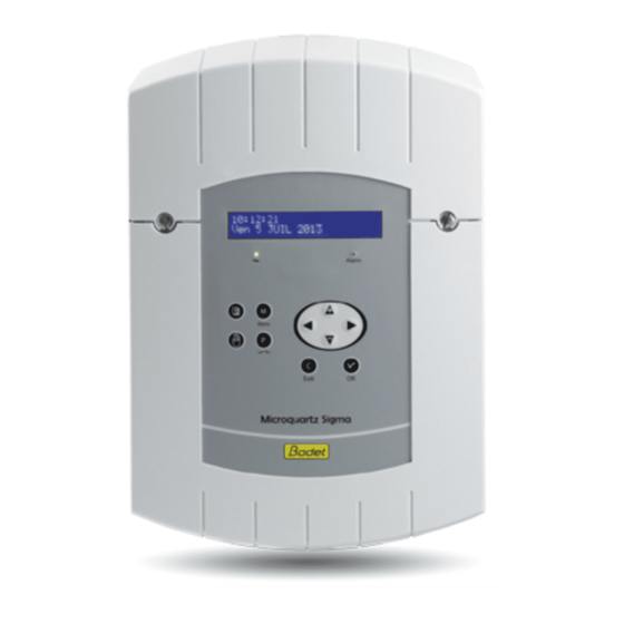
SIGMA
Sigma Mod master clock
Wall Sigma Mod - 110/230V
Wall Sigma Mod - 24V
Rack Sigma Mod - 110/230V
Rack Sigma Mod - 24V
Rack Sigma Mod - 36/72V
www.bodet-time.com
claim with the carrier.
BODET SA
BP30001
49340 TREMENTINES
Tél: +33 241 71 72 99
Fax: +33 241 71 72 01
1
Advertisement
Table of Contents

Related Manuals for Bodet Sigma Mod


Summary of Contents for Bodet Sigma Mod
- Page 1 SIGMA Sigma Mod master clock Installation and start-up instructions The document concerns the following products : 907451 Wall Sigma Mod - 110/230V 907452 Wall Sigma Mod - 24V 907453 Rack Sigma Mod - 110/230V 907454 Rack Sigma Mod - 24V...
-
Page 2: Table Of Contents
Table of contents 1) General 2) Safety rules PROTECTIONS : 3) Description 4) Installation 4.1 Mechanical installation 4.2 Electrical connections 5) Installation examples 5.1 Setting a 24V time distribution 5.2 Setting a DHF time distribution 5.3 Programming a RHF circuit 5.4 Install an option board 5.5 Set a 24V TBT output 6) Keypad: Key functions... - Page 3 10) Programming in Holidays and Special Day mode 11) Technician menu programming 11.1 Time synchronisation menu 11.1.1 Programmable time changeover 11.1.2 Setting the time base 11.2 Time output management menu 11.3 IP configuration menu 11.4 Relay setting menu 11.5 RHF circuit function setting menu 11.6 Function setting menu 11.7 “Delete all programming”...
- Page 4 SIGMA M Installation and start-up instructions...
-
Page 5: General
This product must be installed in a residential, commercial or light industry environment. Bodet declines all responsibility in the event of an accident resulting from use not in accordance with the recommendations of this manual. CAUTION : Any modification on the product renders the guarantee null and void. -
Page 6: Safety Rules
2) Safety rules • Installation and maintenance of this equipment should only be carried out by qualified personnel. • If the SIGMA is connected to the 230 V mains power supply, its installation must comply with the European standard IEC 364 (NFC 15.100 for France). PROTECTIONS : •... - Page 7 • The “RACK” models must be mounted in 19” cabinet. These components will provide mechanical, electrical and fire protection (only the front panel may remain accessible). • IMPORTANT: before any installation, refer to the “technical characteristics” paragraph. • Think of making a backup of your programming on the USB key. In case of incident (breakdown, thunderstorm…), you will just have to restore the backup to start the time distribution again.
-
Page 8: Description
3) Description Wall box A) LCD screen B) Keypad (see page 16) C) Alarm indicator light (red LED) D) Mains indicator light (green LED) E) USB connector F) Relay output terminal strips 19” Rack... -
Page 9: Installation
4) Installation 4.1 Mechanical installation Choose a room with low temperature variations away from any source of electrical interference (contactors, motors, etc.). WALL-MOUNTED version: Unscrew the 2 screws on the front, remove the cover (for the lower cover, press on the 2 clips (N) and slide it upwards). -
Page 10: Electrical Connections
4.2 Electrical connections Connect the cables (mains power supply, impulse line or AFNOR output and radio synchronisation input, depending on the model) to the corresponding terminal strips as shown in the figure below. See the limit characteristics of these circuits on page 59 (**) 110 to 230VAC or... - Page 11 Connection for D1D2 distribution : To Bodet D1 D2 D1D2 movement. Make a shunt between terminals 1 and 3, 0.75² < cross section of wires <1.5². D1 D2 uses the relays of circuits 1 and 2 Circuits must be protected by fuse disconnector or circuit breaker 4A maximum.
- Page 12 Connection of DHF transmitter : There are two types of DHF transmitters. DHF transmitter “Time and relays”, reference 907512, for SIGMA master clocks. Transmitter cable 907512 Yellow White Green Brown DHF transmitter “Time”, reference 927230, for master clocks SIGMA, DELTA, ALFA, etc.
-
Page 13: Installation Examples
5) Installation examples 5.1 Setting a 24V time distribution The 24V time distribution must be connected to the terminals 14 and 15. Apply the power to the SIGMA. Enter the technician menu (see page 32). Impuls 01:MIN 1.2s ú Enter the “time output” menu. Select with the navigation keys : START 00:00 P+ OK - the type of distribution (minute, ½... -
Page 14: Programming A Rhf Circuit
5.3 Programming a RHF circuit Install the wireless relay. Configure the address of the corresponding RHF circuit using the DIP switches from 5 to 8 (default address is 60). Nota : several wireless relays can have the same address as long as control is the same (e.g. -
Page 15: Install An Option Board
5.4 Install an option board Switch off the SIGMA, open it, see page 48. Install the option board in the slot, fix it with the screws provided and put the label in front of it. Connect the output or input lines of this board. Close the SIGMA and switch it on. -
Page 16: Keypad: Key Functions
6) Keypad: Key functions Keys Functions Calendar key. Test key. Menu key. Program key. Correction key. Validation key. Navigation keys. Note: exit from the menus is automatic if a key has not been pressed for one minute in the customer menu or for 5 minutes in the technician menu. - Page 17 Synoptic diagram of the programming Modification of the programming ˙ for holidays and special days + Access code Choice of Load / save Choice of ...
-
Page 18: Main Menu Programming
7) Main menu programming 7.1 Standby state ■ In normal functioning the SIGMA displays the time and date : is the radio signal indicator, which 10:54:32 flashes if reception is poor. ■ If a bank holiday, a special day or a holiday Fri 22 MAY 2014 period has been programmed on this given day, the SIGMA indicates this via a display... -
Page 19: Usb Loading And Backup
7.3 USB loading and backup The SIGMA can load or back up its USB transfer programming via a USB key. Add DHF receivers õ Before creating a new programming with the software, you will need to save the existing one on your USB drive, and transfer. Connect USB key then Validate the option with the key press ok... -
Page 20: Adding Dhf Receivers
7.4 Adding DHF receivers To place the SIGMA in “DHF initialisation” Add DHF receivers ok mode and enable synchronisation of a new Bank Holidays õ clock, validate the initialisation mode with the key, Init mode:ACTIVE ú The following screen is displayed : Select “ACTIVE”... -
Page 21: Bank Holidays
7.5 Bank holidays Bank holidays saved via the PC software (maximum 20 dates) are managed by SIGMA. By default, French bank holidays are active. Bank holidays can be added and configured through the PC software. Validate the option with the key, Bank Holidays Access code... -
Page 22: Time And Date
7.7 Time and date Time and date To change the time or the date of the SIGMA, Dynamic reception õ validate the option with the key, Time zone : LONDON ú The following screen is displayed : (GMT + 00:00) You have access to the time zone selection. -
Page 23: Dynamic Radio
The languages available are : FRENCH, Language:ENGLISH ú ENGLISH, SPANISH, GERMAN, DUTCH, PORTUGUESE, NORWEGIAN, DANISH, ... 7.10 Version Version To view the version of the SIGMA, validate õ the option with the key, The following screen is displayed : SIGMA MOD Version V1.1E05 31/03/2015 o... -
Page 24: Programming The Circuits
8) Programming the circuits The Sigma M has three programmable (hard-wired) circuits allowing contacts (relays) to be activated. The option boards allow relays to be added. See circuit setting programming in the technician menu on page 39. The programming circuit menu is accessed by pressing the key. -
Page 25: Viewing The Circuits
8.1 Viewing the circuits Select the number of the circuit you wish to view with the key. Select DISPLAY mode with the keys and validate with the key The display of the parameters is fixed and Cir.01:08:02:00 03s the step numbers flash. MTWTFS- Weekly 01/12 ú... - Page 26 and then validate with the Proceed in the same way for the minutes and Cir.12:08:02:00 ---ú then the seconds. M T W T F S - W e e k l y 01/01ok Enter the status of the circuit for this program step, choosing from ON, OFF, 01s (length in seconds which can be set using the keys) and DEL (DEL mode...
-
Page 27: Add A Program Step
8.2.1 Add a program step Select the number of the circuit you wish to add a program step using the key. Select the PROG mode with the Cir.01:HH:MM:SS ---ú validate with the key. M T W T F S - W e e k l y 01/01ok Press the key on the first step of program to access to a blank step. -
Page 28: Modify A Program Step
8.2.3 Modify a program step Select the number of the circuit you wish to modify a program step using the key. Select the PROG mode with the Cir.1:08:00:00 06s ú validate with the key. M T W T F S - W e e k l y 03/05ok Select the program step to be modified with key. -
Page 29: Manual Testing Of Circuits
9) Manual testing of circuits While the status of a relay is displayed, it is possible to test it. Select the circuit you wish to test with the Circuit 12: START ú key. Access control The system recognises its mode of assignment (relay or melody). -
Page 30: Programming In Holidays And Special Day Mode
10) Programming in Holidays and Special Day mode The programming of the SIGMA can be modified during a holiday period and for a special day. To access this menu, use the key. It is possible to enter dates for a holiday period or for a special day. By default, Holidays mode flashes. - Page 31 keys and validate with the keys if they are concerned by the holiday period. Dates : Holidays ú If the “ALL EXCEPT” option is validated, only the selected circuits will not be affected by 1 0 / 0 2 Ç 2 5 / 0 2 A l l e x c e p ok the Holidays mode.
-
Page 32: Technician Menu Programming
11) Technician menu programming The technician menu is accessible via an access code sent to the approved persons. Press one of the navigation keys for a few Enter TECHNICIAN code seconds. * ** * A code is then requested. The technician code is a fixed code, You then have access to the technician menu, Validate the required option with the key, or access the following options with key. -
Page 33: Time Synchronisation Menu
11.1 Time synchronisation menu To configure the time synchronisation of the SIGMA, validate the option in the technician menu with the key, Time synchro The following screen is displayed : Time outputs õ Select the time synchronisation mode from the following options: Synchro:EXTERNAL ú... -
Page 34: Programmable Time Changeover
11.1.1 Programmable time changeover This menu can be used to program the summer/winter time changeover dates. It allows you to define the start of the winter Pr og. t im e ch an ge :Y es ú period and then the start of the summer period. -
Page 35: Setting The Time Base
11.1.2 Setting the time base This menu can be used to set the drift of the time base. This can be useful when the master clock has no external synchronisation. Drift:+0.0sec/day ú To access this menu, you need to have Time base setting ok selected “None”... -
Page 36: Time Output Management Menu
11.2 Time output management menu Programming by PC software allows the time zone differential of each output to be set with respect to the local time. This menu can be used to view all the time outputs, modify their status (Start/ Stop), configure the DHF distribution in Init mode and configure the “impulse”... - Page 37 Buzzer mode allows you to activate a buzzer on the secondary transmitters in order to identify them. D1D2 minute:06s ú For an “impulse” or “D1D2” output, the START 00:00 key can be used to go to the configuration menu. Remark: the “D1D2” menu appears only if the relays have been assigned to the D1D2 distribution (see “Relay setting menu”, page 39).
-
Page 38: Ip Configuration Menu
11.3 IP configuration menu This menu is used to configure the IP parameters of the SIGMA. IP setting To enter the SIGMA IP configuration menu, Relay setting õ validate the option in the technician menu with the key DHCP : No ú... -
Page 39: Relay Setting Menu
11.4 Relay setting menu This menu can be used to assign the relays (D1D2 and alarm). Relay setting To go to the SIGMA relay assignment menu, RHF Circuit õ validate the option in the technician menu with the key, The following screen is displayed : Rel. -
Page 40: Rhf Circuit Function Setting Menu
11.5 RHF circuit function setting menu This menu can be used to assign the HF relays (16 address maximum). To go to the SIGMA relay setting menu, RHF Circuit validate the option in the technician menu Function setting õ with the key, CIR.RHF:60 >... -
Page 41: Function Setting Menu
11.6 Function setting menu This menu allows you to define allocation of the external input of the mother board. It depends if you are using the master clock as master or slave unit. If the master clock is used as master, the external input will, for example, control circuitry to drive an alarm or buzzer. -
Page 42: Delete All Programming" Menu
LENGTH starts the relay in ON mode during Ext.input: CIR.01 ú the programming period HH MM SS; pressing START Enter places the circuit in stop mode. FORCED ON: forces the relay position Ext.input: CIR.01 ú whatever the programming (as in test mode); LENGTH HH:MM:SS 1st pressing ON, 2nd pressing OFF. -
Page 43: Cpu Software Download Menu
11.8 CPU software download menu This menu allows you to update the program code in Flash. In the www.bodet-time.com/en/support.html, click on “Downloads”. Download the latest version of the programs into you USB flash drive. To go to this SIGMA menu, validate the Update syst. -
Page 44: Factory Setting Restoration Menu
11.9 Factory setting restoration menu This menu can be used to reinstall the initial factory setting. To go to this SIGMA menu, validate the Factory config. ok option in the technician menu with the õ key, Re sto re c on fi g : No ú The following screen is displayed : f a c t o r y c o n f i g u r a t i o n o k To reinstall the factory configuration, validate... -
Page 45: Priority Of Execution Of Programs
12) Priority of execution of programs Function Priority Circuit 1 in alarm, circuits 2 and 3 in time distribution (D1D2 1 (high) tower clock) Manual control of relays Manual selection of a particular day (bank holiday / day before bank holiday / special day) Programmed special day Programmed holidays and bank holidays Weekly program... -
Page 46: Alarm Messages
13) Alarm messages By default, the alarm configuration is : - Activated: if an alarm is present, a message is displayed on the readout, - Alarm relay: relay 3 is activated if an alarm is triggered. - E-mail: the Sigma sends an e-mail (see messaging programming in the PC software), - SNMP: the SNMP server will receive a message (trap). - Page 47 Alarm message Meaning The user code has been entered three times incorrectly; the user code keyboard is blocked for 10 minutes. fail. The technician code has been entered three times incorrectly; the tech.code keyboard is blocked for 10 minutes. fail. The lithium battery used to save configuration data is defective;...
-
Page 48: Options
14) Options The Sigma M can be fitted with option boards to extend its capacities. The wall-mounted Sigma MOD can be fitted with 2 extension boards, and the rack type Sigma MOD with 4 boards. The option boards are installed “cold” and are automatically recognised when the master clock is switched on. -
Page 49: Option Board With 3 Afnor Outputs
14.2 Option board with 3 AFNOR outputs Output A Output B Output C This option board does not require any software programming (by default the time is the local time defined in the Sigma and the line is stopped). Only the time zone differential and the state of the line (On / Off) is to be defined in the “Time outputs”... -
Page 50: Option Board With 2 Ascii Outputs
The ASCII frame, the speed and the number of bauds are programmed on PC using the software. The default programming is periodic sending of a message to Bodet switchboard 1 every second, at 9600 bauds, on 8 bits with no parity and 1 stop bit, and the time is the local time defined in the Sigma. - Page 51 Connection to a PC in RS232 mode 9 pins 25 pins Sigma board connector Ground Maximum length from Sigma to P.C. with RS232: 15 m Synchronisation connection to a PC in RS422 Position of MA 45 Sigma board interface DIP switches: Interface Link in RS422 Link in RS232...
-
Page 52: Option Board Impulse
14.4 Option board impulse // Jumper to adjust maximum amperage Power DIP switches 0,5A Both on V EXT = external power Both on V INT = internal power. External power input 20-50V DC Impulse output This option board does not require any software programming. It allows to add a minute, ½... -
Page 53: Option Board With 2 Serial Outputs (24Vdc Power Supply)
14.5 Option board with 2 serial outputs (24VDC power supply) Output A Output B Résistor Current setting (10 k) This option board does not require any programming. By default the time is the local time defined in the Sigma, with 1.2-second impulses, and the line is stopped. -
Page 54: Option Board With 2 Serial Outputs (48Vdc Power Supply)
14.6 Option board with 2 serial outputs (48VDC power supply) Power supply +48VDC Output A Power input/ output Output B Résistor Current setting (10 k) This option board does not require any programming. By default the time is the local time defined in the Sigma, with 1.2-second impulses, and the line is stopped. - Page 55 Resetting to the correct time can be carried Impuls 05:1/2M 1.2s ú out line by line. STOP set dial In the time output management menu of the technician menu, use the key to move to “set dial” and validate with The following screen is displayed : Dials : A:00:00 ú...
-
Page 56: Relay Option Board
14.7 relay option board Circuit C1 Circuit C2 Circuit C3 This option board does not require any software programming. It allows 3 relays to be added. See the technician menu (circuit setting programming) on page 39. Remark: in the time output management menu of the technician menu, “DEL” mode is used only to uninstall the option board from the master clock. -
Page 57: Option Board With Afnor Input
14.8 Option board with AFNOR input AFNOR input This option board does not require any software programming. It allows to add an AFNOR synchronisation input. See “Time outputs” in the technician menu page 36. -
Page 58: Three Inputs Option Card
14.9 Three inputs option card Input A Input B Input C This card allows the addition of 3 external inputs. Connect the lines carrying the external information to the inputs A, B and C. The parameter setting is accomplished with the PC software. See paragraph “USB loading and backup”... -
Page 59: Technical Characteristics
15) Technical characteristics Designation Characteristics Backup Permanent backup of all parameters in case of mains failure. Automatic resetting of receiver clocks to correct time after mains restoration. Time base Quartz, accuracy 0.1 seconds per day between 20 and 25°. Capacity 500 program steps per circuit. - Page 60 Protection index Wall-mounted : IP41 / Rack : IP 20 Operating temperature 0 to 50°C Keypad locking By access code Dimensions WALL-MOUNTED version 19» RACK Version Width 220 mm 483 mm (1 width) Height 322 mm 44 mm (1 U) Depth 83 mm 200 mm...
-
Page 61: Appendix I : Ntp Programming
Appendix I : NTP programming IP function programming The programming is carried out in 2 steps. 1 – Program the IP output (parameters supplied by the network administrator) from the technician menu of the master clock (see page 38). 2 – Software configuration. Start the PC software and then load the USB backup of your Sigma M. - Page 62 It is possible to add the key number of the server to make the distribution secure. The “Force master clock time setting with respect to server on starting” option will order the master clock to connect to the address of the server and take the time there on starting.
-
Page 63: Ip Network Configuration And Protocols Supported
IP network configuration and protocols supported : - Ethernet 10/100 BASE-T network via RJ45 with 10/100 automatic switching. - NTP V2, V3 and V4 - NTP in unicast mode, - NTP in broadcast mode, - NTP in multicast mode, - Possible protection by secret keys, - capacity: maximum 500 connections per second. -
Page 64: What To Do If
>Send the equipment back to the BODET maintenance department. seconds per day) of the time base. An alarm is displayed. >To acknowledge the alarm, after setting the problem with this alarm, press the button and confirm If the problem persists, call for Bodet technical support.
Need help?
Do you have a question about the Sigma Mod and is the answer not in the manual?
Questions and answers