Table of Contents

Subscribe to Our Youtube Channel
Related Manuals for Bodet SIGMA H


Summary of Contents for Bodet SIGMA H
- Page 1 SIGMA H Installation and start-up instructions B.P. 1 49340 TRÉMENTINES FRANCE Tél. : 02 41 71 72 00 Fax : 02 41 71 72 01 www.bodet.com Réf.:606528 J Check the product for shipping damage on reception for any reservations to the carrier...
-
Page 2: Table Of Contents
Ta ble of con tents 1) Gen eral....................3 2) Safety rules ..................4 PROTECTIONS : ..................4 3) De scrip tion ..................6 4) Key pad: Key func tions ..............7 5) Main menu pro gram ming ..............9 5.1 Standby state ..................9 5.2 User menu..................9 5.3 USB load ing and backup ...............10 5.4 Add ing DHF re ceiv ers ..............11 5.5 Ac cess code..................11... -
Page 3: General
This product must be installed in a residential, commercial or light industry environment. Bodet declines all responsibility in the event of an accident resulting from use not in accordance with the recommendations of this manual. CAUTION : Any modification on the product renders the guarantee null and void. -
Page 4: Safety Rules
2) Safety rules Maintenance of this equipment must be carried out by qualified personnel. If the SIGMA is connected to the 230 V mains power supply, its installation must comply with the European standard IEC 364 (NFC 15.100 for France). PROTECTIONS : 110-230V version: the mains supply for this device must include a neutral phase circuit breaker of maximum 6 A C curve, rapidly accessible... - Page 5 “Rack” models must be mounted in a slide-in unit for 19” cabinets or racks. These components will provide mechanical, electrical and fire protection (only the front panel may remain accessible). IMPORTANT: before any installation, refer to the “technical characteristics” paragraph. Caution : In case of replacement of the CR2032 battery, it is IMPERATIVE to respect the...
-
Page 6: Description
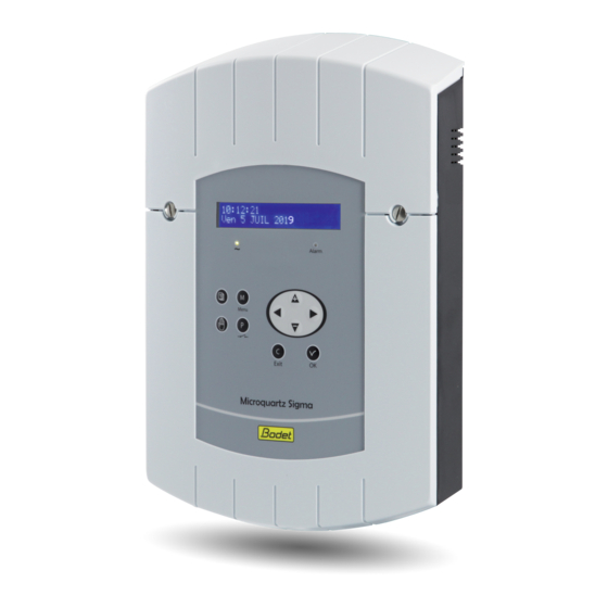
3) Description Wall box 19" Rack A) LCD screen B) Keypad (see page 6) C) Alarm indicator light (red LED) D) Mains indicator light (green LED) E) USB connector... -
Page 7: Keypad: Key Functions
4) Keypad: Key functions Keys Functions Menu key. Correction key. Validation key. Navigation keys. Note: exit from the menus is automatic if a key has not been pressed for one minute in the customer menu or for 5 minutes in the technician menu. - Page 8 Synoptic diagram of the programming + Access code Choice of Load / save the time programming synchronisation Time output Put in management INIT mode Activation of the backlight Access code YES / NO Choice of Master or slave operation Setting of time, date and time zone Update the...
-
Page 9: Main Menu Programming
5) Main menu programming 5.1 Standby state In normal functioning the SIGMA displays the time and date : is the radio signal indicator, which flashes if reception is poor. 5.2 User menu To access the user menu, press the menu key Enter the user access code if necessary (see page 11). -
Page 10: Usb Loading And Backup
5.3 USB loading and backup The SIGMA can load or back up its programming via a USB key. Validate the option with the key, The following screen is displayed : Insert the USB key and validate with the key. To load a Program in the Sigma : Validate the option with the key, The SIGMA will search for the files... -
Page 11: Adding Dhf Receivers
5.4 Adding DHF receivers To put the SIGMA in “DHF initialisation” mode and enable synchronisation of a new clock, validate the initialisation mode with the key, The following screen is displayed : Select “ACTIVE” mode using the keys and validate with the key. -
Page 12: Time And Date
5.6 Time and date To change the time or the date of the SIGMA, validate the option with the key, The following screen is displayed : You have access to the time zone selection. The time zone selection allows you to automatically manage winter/summer time changeovers. -
Page 13: Dynamic Radio Reception
5.7 Dynamic radio reception To view the dynamic reception of the SIGMA, validate the option with the key, If the reception is correct, the time and date are constructed automatically. If the SIGMA is synchronised by a GPS antenna, the time displayed is GMT. If the SIGMA is synchronised by a France-Inter or DCF antenna, the radio time is displayed. -
Page 14: Technician Menu Programming
6) Technician menu programming The technician menu is accessible via an access code sent to the approved persons. Press one of the navigation keys for a few seconds. A code is then requested. The technician code is a fixed code, You then have access to the technician menu with the key. -
Page 15: Time Synchronisation Menu
6.1 Time synchronisation menu To configure the time synchronisation of the SIGMA, validate the option in the technician menu with the key, The following screen is displayed : Select the time synchronisation mode from the following options: FI/DCF Radio, Minute radio (mode used for countries receiving the FI/DCF radio signal but for which the time is different from Paris/Berlin [only minute is synchronised, date and hour must be set manually]), EXTERNAL (mode used for synchronisation from a Sigma “Master”... - Page 16 6.1.1 Programmable time changeover This menu can be used to program the summer/winter time changeover dates. It allows you to define the start of the winter period and then the start of the summer period. To program the summer/winter time changeovers, validate with the key.
- Page 17 6.1.2 Setting the time base This menu can be used to set the drift of the time base. This can be useful when the master clock has no external synchronisation. To access this menu, you need to have selected “None” mode in the external synchronisation menu.
-
Page 18: Time Output Management Menu
6.2 Time output management menu This menu can be used to view all the time outputs, modify their status (Start/Stop), configure the DHF distribution in Init mode and configure the “impulse” and “D1D2" distribution. This menu allows you also to configure the impulse output (Impuls 01) to provide TBT 24VDC (0,5A) power supply. - Page 19 Buzzer mode allows you to activate a buzzer on the secondary transmitters in order to identify them. For an “impulse” or “D1D2" output, the key can be used to go to the configuration menu. Remark: the “D1D2" menu appears only if the relays have been assigned to the D1D2 distribution (see “Relay setting menu”, page 17).
-
Page 20: Function Setting Menu
6.3 Function setting menu This menu can be used to define whether the master clock functions as a master or as a secondary clock (slave). It can also be used to activate the backlight of the display screen. To go to the SIGMA function setting menu, validate the option in the technician menu with the key, The following screen is displayed :... -
Page 21: Factory Setting Restoration Menu
The following screen is displayed : to download, validate with the key, The following screen is displayed : validate with the key. 6.5 Factory setting restoration menu This menu can be used to reinstall the initial factory setting. To go to this SIGMA menu, validate the option in the technician menu with key, The following screen is displayed : To reinstall the factory configuration,... -
Page 22: Alarm Messages
7) Alarm messages By default, the alarm configuration is : – Activated: if an alarm is present, a message is displayed on the readout, – Alarm relay: relay 3 is activated if an alarm is triggered. If an alarm is active, the display alternates between the date and the alarm message. - Page 23 Alarm message Meaning The user code has been entered three times incorrectly; the keyboard is blocked for 10 minutes. The technician code has been entered three times incorrectly; the keyboard is blocked for 10 minutes. The lithium battery used to save configuration data is defective; replace the battery after making a backup of configuration data.
-
Page 24: Installation
8) Installation 8.1 Mechanical installation Choose a room with low temperature variations away from any source of electrical interference (contactors, motors, etc.). WALL-MOUNTED version: Unscrew the 2 screws on the front, remove the cover (for the lower cover, press on the 2 clips (N) and slide it upwards). -
Page 25: Electrical Connections
8.2 Electrical connections Connect the cables (mains power supply, impulse line or AFNOR output and radio synchronisation input, depending on the model) to the corresponding terminal strips as shown in the figure below. See the limit characteristics of these circuits on page 28. - Page 26 Connection for D1D2 distribution : D1 D2 uses the relays of circuits 1 and 2 D1 D2 To Bodet D1D2 movement Power supply Make a shunt between terminals terminal strip 1, 3 and phase, 0.75² < cross section of wires <1.5².
- Page 27 Connection of DHF transmitter : There are two types of DHF transmitters. DHF transmitter “Time and relays”, reference 907511, for SIGMA master clocks. Transmitter cable 907511 Yellow White Green Brown DHF transmitter “Time”, reference 927240, for master clocks SIGMA, DELTA, ALFA, etc. Note: the INIT mode must be activated directly from a DIP switch on the electronic card of this transmitter (not from the master clock).
-
Page 28: Technical Characteristics
9) Technical characteristics Designation Characteristics Backup Permanent backup of all parameters in case of mains failure. Automatic resetting of receiver clocks to correct time after mains restoration. Time base Quartz, accuracy 0.1 seconds per day between 20 and 25°. Power supply 115 or 230 V AC ±... - Page 29 Depending on model, on FI, DCF, MSF or GPS antenna. Synchronisation Minute or half minute 1 output 24V 0,5A, configuration in minute, ½ minute or parallel polarised second impulse or SR2-59 or TBT 24V power supply. impulse distribution D1D2 distribution One output (D1 D2 uses the relays of circuits 1 and 2).
-
Page 30: What To Do If
> Wait at least 4 minutes. flashing. >Refer to the section on setting the time base drift Drift of the time base. (page 17). >Send the equipment back to the BODET maintenance Considerable drift (> 0.5 department. seconds per day) of the time base. -
Page 31: Installation Examples
11) Installation examples 11.1 Set the 24V impulse output Connect the 24V impulse clock line to the terminals 14 and 15. Switch on the SIGMA. Access to the technician menu (see page 14). Access to the menu “Time outputs”. Use the navigation keys to : –... -
Page 32: Set A 24V Tbt Output
11.3 Set a 24V TBT output The 24V must be connected to the terminals 14 and 15. Switch on the SIGMA. Enter the technician menu (see page 14). Enter the “Time outputs” menu. Use the navigation keys to select : TBT24V.
Need help?
Do you have a question about the SIGMA H and is the answer not in the manual?
Questions and answers