Table of Contents
Advertisement
Quick Links
INSTALLATION & USER INSTRUCTIONS
Christchurch, Dorset BH23 2BT
Tel: 01202 588 638
Fax: 01202 499 639
www.ekofires.co.uk
e-mail: sales@ekofires.co.uk
IN THE UK ALWAYS USE A GAS SAFE REGISTERED ENGINEER TO INSTALL, REPAIR OR SERVICE THIS APPLIANCE
Please note : Except where otherwise stated, all rights,
including copyright in the text, images and layout of this
booklet is owned by Focal Point Fires plc. You are not per-
mitted to copy or adapt any of the content without the
prior written permission of Focal Point Fires plc.
WALL INSET GAS FIRES
MODELS COVERED BY THESE INSTRUCTIONS
8010 WALL INSET GAS FIRE
8020 WIDE WALL INSET GAS FIRE
AVAILABLE IN SLIDE CONTROL & REMOTE CONTROL
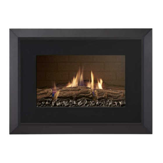
MODEL SHOWN : EKO 8010 WALL INSET GAS FIRE
1
All instructions must be handed to the user
for safekeeping.
Revision A - 05/17
GB IE
© 2017 Focal Point Fires plc
Advertisement
Chapters
Table of Contents

Subscribe to Our Youtube Channel
Related Manuals for Ekofires 8010


Summary of Contents for Ekofires 8010
- Page 1 Fax: 01202 499 639 www.ekofires.co.uk e-mail: sales@ekofires.co.uk MODEL SHOWN : EKO 8010 WALL INSET GAS FIRE IN THE UK ALWAYS USE A GAS SAFE REGISTERED ENGINEER TO INSTALL, REPAIR OR SERVICE THIS APPLIANCE Please note : Except where otherwise stated, all rights,...
-
Page 2: Table Of Contents
I N S T A L L A T I O N I N S T R U C T I O N S GB IE Section Contents Page No. Section Contents Page No. Important Notes Assembling the Appliance Appliance Data Operating the Appliance Installation Requirements Operating Pressure -... -
Page 3: Appliance Data
2.0 APPLIANCE DATA GB IE Operating Pressure Max Energy Min Energy Input Country of Model Gas Type (±2.0 mbar) Input (kW) (kW) Destination G20 G25 G30 G31 Gross Gross I 2H Natural Gas Wall inset slide control models GB - IE I 2H Natural Gas Wall inset remote control models GB - IE... - Page 4 4.0 SITE REQUIREMENTS - CONTINUED GB IE Whilst a hearth is not required under regulations, it may be adviserable to fit a hearth as a tactile barrel against “walk on” or clothes drying. Any existing under grate draught device must be sealed off.The fireplace wall must be non-combustible. Figure 1 Note: dimensions in italics refer only to wide wall inset models.
-
Page 5: Ventilation
5.0 VENTILATION GB IE No purpose provided ventilation is normally required for this appliance.The requirements of other appliances operating in the same room or space must be taken into consideration when assessing ventilation. If spillage is detected when commissioning the appli- ance, then amongst other problems there may be insufficient natural ventilation for correct operation of the flue. -
Page 6: Preparing The Opening
7.0 PREPARING THE APPLIANCE - CONTINUED GB IE Remove the burner unit by removing the two Figure 4 Figure 5 screws either side of the burner as shown in figure 4. The tray is now free, and may be lifted away. Remove the internal firebox from the external firebox via the six screws highlighted in figure 5. -
Page 7: Installing The Firebox
7.3 INSTALLING THE FIREBOX GB IE Remove any protective film coatings from the finished/decorative surfaces of the appliance. After having selected the final mounting posi- tion of the appliance, taking into account the requirements as specified in sections 3 and 4 WARNING of these instructions, the integrity of the wall, and the feasibility of the proposed supply pipe routing, the firebox of the appliance may be secured to the wall. -
Page 8: Installing The Burner
7.5 INSTALLING THE BURNER GB IE Replace burner unit by screwing the two screws either side of the burner as shown in Figure 14 figure 14. 7.6 GAS CONNECTION Important Note: Check the thermocouple nut connection into the rear of the valve is secure. Temporarily fit the burner unit and ensure a suitable gas route can be achieved. -
Page 9: Operatingtheappliance
8.4 OPERATINGTHEAPPLIANCE GB IE For operating instructions for the appliance please refer to sections 5.0 and 5.1 of the users instructions. 8.5 OPERATING PRESSURE - SLIDE & REMOTE CONTROLS Release the pressure test point screw, and attach a pressure gauge. Light the fire on the Figure 17 HIGH setting. -
Page 10: Final Assembly
8.7 TESTING FOR SPILLAGE - CONTINUED GB IE All the smoke should be drawn away up the flue. Any smoke returning into the room indicates that spillage is occurring. If the spillage test fails and the spigot restrictor is fitted, remove the spigot restrictor, re-fit and re-test. If the initial spillage test fails, run the fire for a further 10 minutes and repeat the test.When the test has been completed satisfactorily, repeat with any extractor fans in the premises running on the highest setting, and any communicating doors open. -
Page 11: Servicing
10.0 SERVICING GB IE Isolate the fire from the gas supply. Ensure that the fire is fully cold before attempting service. A suggested procedure for servicing is detailed below 1. Lay out the dust sheet and tools. 2. Carefully remove the decorative front. (see section 8.9) 3. -
Page 12: Removing The Firebox
10.5 REMOVING THE FIREBOX GB IE Remove the burner unit as described previously. Protect the opening from potential damage. Remove the screws holding the inner firebox into position. Remove the four screws holding the flue adaptor into position. Disconnect the flue. Next, unscrew the external firebox from the wall.The firebox is now released from the opening and can be slid outwards. - Page 13 11.0 TROUBLESHOOTING GUIDE - CONTINUED GB IE • If the pilot will not stay lit there could be a problem with contamination of the Fire runs for a time and then cuts off gas supply, drafts, ventilation or the thermocouple needs replacement. Modifications are dangerous and can have a serious unseen effect on safety.
-
Page 14: Clearances To Combustibles
U S E R I N S T R U C T I O N S GB IE Section Contents Page No. Section Contents Page No. Important Notes Servicing Clearances to Combustibles Cleaning Fireguards 10.0 Replacing the Batteries- Remote Controls Ventilation 10.1 Replacing the Batteries-... -
Page 15: Fireguards
3.0 FIREGUARDS GB IE The fireguards specified in BS 8423 are intended to protect people from falling into a fire, prevent burns and reduce the risk of injury, particu- larly to young children and the infirm. In addition it is intended to reduce the risk of fire resulting from clothing and/or other flammable mate- rials coming into contact with, or in proximity to, burning fuel and/or hot surfaces. - Page 16 5.1 OPERATINGTHE FIRE - REMOTE CONTROL MODELS GB IE TO TURN ON APPLIANCE STAND BY MODE (Pilot Flame) When pilot ignition is confirmed, motor turns automatically Handset to maximum flame height. Press and hold (small flame) to set appliance at pilot flame.
- Page 17 5.1 OPERATINGTHE FIRE - REMOTE CONTROL MODELS GB IE Modes of operation NOTE: Manual mode can also be Briefly pressing the SET button changes the reached by pressing either mode of operation in the following order: the (large flame) or the (small flame) button.
- Page 18 5.1 OPERATINGTHE FIRE - REMOTE CONTROL MODELS GB IE Press (small flame) button to Press (large flame) button to increase decrease Daytime Set Temperature. Daytime Set Temperature. Press OFF or simply wait to complete pro- Setting the “NIGHTTIME gramming. SETBACK” Temperature DEFAULT SETTINGS:TEMP (moon), “...
- Page 19 5.1 OPERATINGTHE FIRE - REMOTE CONTROL MODELS GB IE Setting P1 ON Time Select Timer Mode by briefly pressing the Hold the SET button until P1 SET button. and (sun) are displayed and the time flashes. Set the hour by pressing the (large flame) Set the minutes by pressing the button.
-
Page 20: Flue Spillage Monitoring System
6.0 FLUE SPILLAGE MONITORING SYSTEM GB IE This fire is fitted with a flue spillage safety device (ODS). If the fire shuts down during use for no apparent reason then several reasons may be suspected. If a door or window has been opened creating a draught, then pilot disturbance could be the problem, and removal of the draught should resolve this. -
Page 21: Fuel Bed Layout - Wide Wall Inset
7.1 FUEL BED LAYOUT - WIDE WALL INSET GB IE 1. Remove the ceramic logs from their protective packaging. All logs are Figure 7 marked on the rear or the underside from letters “A” to “J”. Place the log marked ‘A’ on the top left rear ledge behind the burner mixer chamber as shown in figure 7. - Page 22 7.1 FUEL BED LAYOUT - LOG EFFECT GB IE - CONTINUED 6. Place the log marked ‘F’ on the right hand side in the front section Figure 13 of the burner. Figure 14 7. Next carefully place log ‘G’ over the top of log ‘A’ and log ‘D’. 8.
-
Page 23: Servicing
7.1 FUEL BED LAYOUT - LOG EFFECT GB IE - CONTINUED Before re-assembling the appliance turn the appliance ON and check that Figure 18 none of the flames come into contact with any of the cross logs. If the logs do come into contact with a flame. Wait for the fire to cool down then re-adjust the cross logs so it is clear of any flames. -
Page 24: List Of Replacement Parts
11.0 LIST OF REPLACEMENT PARTS GB IE Item Part number Pack of 3 ceramic logs - (Wall inset models) F550436 Pack of 10 ceramic logs - (Wide wall inset models) F550466 Ceramic pad set includes rear pad and side pads - (Wall inset models) F550433 Ceramic pad set includes rear pad and side pads - (Wide wall inset models) F550465... -
Page 25: Guarantee - Terms And Conditions
Eko Fires ltd, 3G Service Department, Reid Street, Christchurch, Dorset, BH23 2BT. Alternatively email: service@ekofires.co.uk or fax. 01202 499326. Details required: 1. Name, full address including post code and contact telephone number.
Need help?
Do you have a question about the 8010 and is the answer not in the manual?
Questions and answers