Table of Contents
Advertisement
INSTALLATION & USER INSTRUCTIONS
RADIANT/CONVECTOR INSET GAS FIRE
Christchurch, Dorset BH23 2BT
Tel: 01202 588 638
Fax: 01202 499 639
www.ekofires.co.uk
e-mail: sales@ekofires.co.uk
PLEASE NOTE: EKO 3010, 3015, 3020, 3025 GAS FIRES MAY BE SUPPLIED WITH DIFFERENT FRET &
IN THE UK ALWAYS USE A GAS SAFE REGISTERED ENGINEER TO INSTALL, REPAIR OR SERVICE THIS APPLIANCE
Please note : Except where otherwise stated, all rights, including
copyright in the text, images and layout of this booklet is owned by
Focal Point Fires plc. You are not permitted to copy or adapt any of
the content without the prior written permission of Focal Point Fires
plc.
MODELS COVERED BY THESE INSTRUCTIONS
3010, 3015, 3020 & 3025 GAS FIRES*
*AVAILABLE WITH MANUAL, SLIDE CONTROL & REMOTE CONTROL
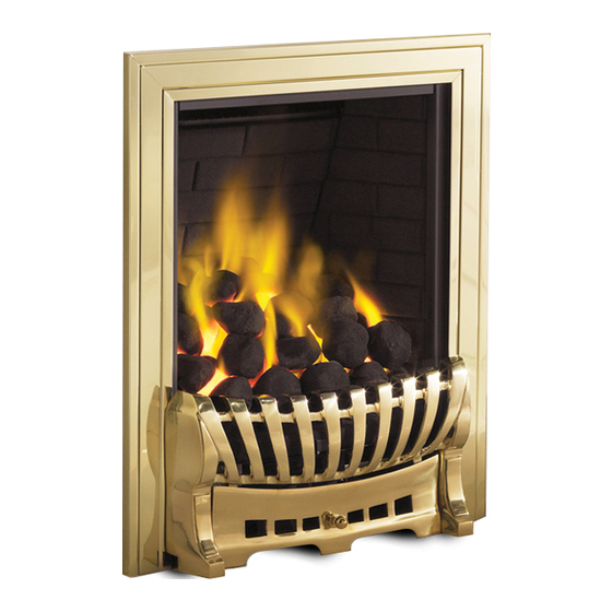
MODEL SHOWN: EKO 3020
FRAMES THAN SHOWN
1
All instructions must be handed to the user for
safekeeping.
Revision F - 03/13
GB IE
BS 7977-1 : 2009
BS EN 509 : 2000
KM579168
© 2013 Focal Point Fires plc.
Advertisement
Chapters
Table of Contents

Subscribe to Our Youtube Channel
Related Manuals for Ekofires 3010


Summary of Contents for Ekofires 3010
- Page 1 KM579168 MODEL SHOWN: EKO 3020 PLEASE NOTE: EKO 3010, 3015, 3020, 3025 GAS FIRES MAY BE SUPPLIED WITH DIFFERENT FRET & FRAMES THAN SHOWN IN THE UK ALWAYS USE A GAS SAFE REGISTERED ENGINEER TO INSTALL, REPAIR OR SERVICE THIS APPLIANCE...
-
Page 2: Table Of Contents
I N S T A L L A T I O N I N S T R U C T I O N S GB IE Section Contents Page No. Section Contents Page No. Important Notes 16.0 Testing and Commissioning Appliance Data 16.1 Operating the Fire (Manual control) -
Page 3: Appliance Data
2.0 APPLIANCE DATA GB IE Destination Operating Pressure Model Max Energy Input (kW) Min Energy Input (kW) Country (±2.0 mbar) Natural Gas Gross Gross I 2H Manual control GB - IE 3.15 I 2H Remote control GB - IE 17.5 3.15 I 2H Slide control... -
Page 4: Debris Collection Space
4.0 SITE REQUIREMENTS - CONTINUED GB IE All models : This appliance requires a natural draught flue system which may be one of the following; 225mm x 225mm (9in x 9in) brick or stone. 125mm (5in) minimum diameter lined brick or stone. 125mm (5in) minimum diameter twin wall flue conforming to BS 715. -
Page 5: Ventilation
5.0 VENTILATION GB IE No purpose provided ventilation is normally required for this appliance.The requirements of other appliances operating in the same room or space must be taken into consideration when assessing ventilation. If spillage is detected when commissioning the appli- ance, then amongst other problems there may be insufficient natural ventilation for correct operation of the flue. -
Page 6: Preparing The Appliance
8.0 PREPARING THE APPLIANCE GB IE Note: Ensure that the gas supply is isolated before commencing installa- Figure 3 - Convector models tion of the appliance. The fireplace opening and environment must be in compliance with specifications laid down in the appropriate sections of these instructions. Remove the appliance from the carton as described previously and stand on a dust sheet or similar. -
Page 7: Gas Supply Routing
10.0 GAS SUPPLY ROUTING GB IE When the opening is ready for installation of the fire, the gas supply may be routed as per the examples shown in figure 7. Wherever a concealed connection is made a rubber grommet must be used to seal the firebox.The gas pipe must be suitably protected where it passes through fireplace openings. -
Page 8: Gas Connection
13.0 GAS CONNECTION GB IE If running a concealed gas supply, ensure grommets are secure around incoming pipes. Important Note: Check the thermocouple nut connection into the rear of the valve is secure. 14.0 FUEL BED LAYOUT Please refer to section 7.0 of the user instructions. 15.0 FITTING THE FIREFRONT/FRAME All models : Remove all protective film and packaging material before fitting. -
Page 9: Operating The Fire (Slide Control)
16.2 OPERATING THE FIRE - CONTINUED GB IE Upon lighting and after the further 10 seconds, release the knob and turn further to the left to the ON position.The main burner will light and be controlled in accordance with the main burner con- trol knob setting. -
Page 10: Testing For Spillage
16.7 TESTING FOR SPILLAGE GB IE Close all doors and windows to the room containing the appliance. Let the fire run on HIGH for five minutes. Take a smoke match, light it, and using a smoke match tube, hold it at the top edge of the fire opening, 25mm down and 25mm in. Starting 50mm in from either side, run the smoke match across the opening. -
Page 11: Cleaning The Ceramics
17.1 CLEANING THE CERAMICS GB IE Remove the firefront and place to one side. Remove the ceramic components. Gently clean in the open air. Be careful not to create dust from the coals.Where necessary replace damaged components with genuine spares. Seal scrap ceramic components in plastic bags and dispose at proper refuse sites as directed. -
Page 12: Troubleshooting Guide
18.0 TROUBLESHOOTING GUIDE GB IE • No gas to fire, check isolators are open and gas supply is on. Fire sparks but pilot does not light • Pipework blockage, clean out. • Air not fully purged, re purge supply or wait longer. •... -
Page 13: Clearances To Combustibles
U S E R I N S T R U C T I O N S GB IE Section Contents Page No. Section Contents Page No. Important Notes Fuel Bed Layout - pebble effect Clearances to Combustibles Fuel Bed Layout - rounded coal effect Fire Guards Servicing Ventilation... -
Page 14: Fire Guards
3.0 FIRE GUARDS GB IE The fireguards specified in BS 8423 are intended to protect people from falling into a fire, prevent burns and reduce the risk of injury, particularly to young children and the infirm. In addition it is intended to reduce the risk of fire resulting from clothing and/or other flammable materials coming into contact with, or in proximity to, burning fuel and/or hot surfaces. -
Page 15: Operating The Fire - Remote Control
5.1 OPERATINGTHE FIRE - REMOTE CONTROL MODELS GB IE The pilot is visible through the left hand side of Figure 4 the matrix. When cold, the coals or pebbles may be rotated for good viewing. Turn the main burner control (shown on left hand side of control valve) knob fully anti-clockwise. -
Page 16: Fuel Bed Layout - Ripped Coal Effect
7.0 FUEL BED LAYOUT - RIPPED COAL EFFECT GB IE Figure 7 This fire is supplied with 15 ceramic ripped coals. Fit the tapered brick pad into the securing brackets in the upper area of the fire- box. Place the large brick panel against the rear of the firebox. Figure 8 Place the ceramic combustion matrix onto the burner and the ceramic side cheeks onto the matrix. -
Page 17: Fuel Bed Layout - Rounded Coal Effect
7.1 FUEL BED LAYOUT - PEBBLE EFFECT - CONTINUED GB IE Figure 13 Place the front row of six pebbles on to the matrix. Ensure the pebbles are firmly against the side cheeks as shown in the photograph. If necessary, pull the pebbles forward slightly to ensure their rear edges do not overhang the flame ports. -
Page 18: Servicing
7.2 FUEL BED LAYOUT - ROUNDED COAL EFFECT GB IE Figure 19 Finally, place the rear row of two coals. IMPORTANT : The fire is designed to operate correctly with the coals supplied when assembled according to the instructions. Never add to the fifteen coals, or change them for a different type. -
Page 19: List Of Replacement Parts
11.0 LIST OF REPLACEMENT PARTS GB IE Item Part number Pack of 15 Ripped coals F780094 Pack of 15 Pebbles F550057 Pack of 11 Moulded coals F550059 Ceramic fuel bed - Ripped coal models F780093 Ceramic fuel bed - Pebble models F780035 Ceramic fuel bed - Moulded coal models F780034... -
Page 20: Service History
13.0 SERVICE HISTORY GB IE Date of service Serviced by (name): GAS SAFE No. : Contact details of Engineer 14.0 GUARANTEE - TERMS AND CONDITIONS The 3 year guarantee only covers products purchased on or after 1st February 2009. For all gas fires purchased the 3 year guarantee commences from the date of purchase, provided that the following 3 terms and conditions are adhered to: Registration is not required.
Need help?
Do you have a question about the 3010 and is the answer not in the manual?
Questions and answers