Table of Contents
Advertisement
INSTALLATION & USER INSTRUCTIONS
FULL DEPTH RADIANT & CONVECTOR GAS FIRES
Christchurch, Dorset BH23 2BT
Tel: 01202 588 638
Fax: 01202 499 639
www.ekofires.co.uk
e-mail: sales@ekofires.co.uk
PLEASE NOTE: EKO 3030
IN THE UK ALWAYS USE A GAS SAFE REGISTERED ENGINEER TO INSTALL, REPAIR OR SERVICE THIS APPLIANCE
Please note : Except where otherwise stated, all rights,
including copyright in the text, images and layout of this
booklet is owned by Focal Point Fires plc. You are not per-
mitted to copy or adapt any of the content without the
prior written permission of Focal Point Fires plc.
MODELS COVERED BY THESE INSTRUCTIONS
3030, 3035, 3040, 3060, 3065, 3070, 3080, 3085, 3090 & 3095 GAS FIRES
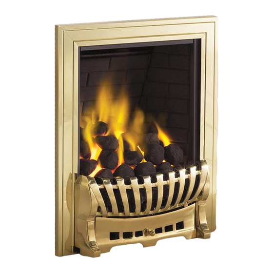
MODEL SHOWN: EKO 3030 GAS FIRE
3035 3040, 3060, 3065, 3070, 3080, 3085, 3090 & 3095
,
SUPPLIED WITH DIFFERENT FRETS THAN SHOWN
All instructions must be handed to the user
for safekeeping.
1
GB IE
BS7977-1 : 2009
KM579168
GAS FIRES MAY BE
GAS FIRES
Revision D - 03/13
© 2013 Focal Point Fires plc
Advertisement
Chapters
Table of Contents

Related Manuals for Ekofires EKO 3030


Summary of Contents for Ekofires EKO 3030
- Page 1 Fax: 01202 499 639 www.ekofires.co.uk e-mail: sales@ekofires.co.uk BS7977-1 : 2009 KM579168 MODEL SHOWN: EKO 3030 GAS FIRE PLEASE NOTE: EKO 3030 3035 3040, 3060, 3065, 3070, 3080, 3085, 3090 & 3095 GAS FIRES MAY BE GAS FIRES SUPPLIED WITH DIFFERENT FRETS THAN SHOWN...
-
Page 2: Table Of Contents
I N S T A L L A T I O N I N S T R U C T I O N S GB IE Section Contents Page No. Section Contents Page No. Important Notes 12.0 Testing and Commissioning Appliance Data 12.1 Operating the Fire (Manual control) -
Page 3: Appliance Data
2.0 APPLIANCE DATA GB IE Destination Operating Pressure Model Max Energy Input (kW) Min Energy Input (kW) Country (±2.0 mbar) Natural gas Gross Gross I 2H Manual control models GB - IE 3.15 I 2H Slide control models GB - IE 15.8 3.15 I 2H... -
Page 4: Debris Collection Space
4.0 SITE REQUIREMENTS - CONTINUED GB IE Note: The spigot outlet of the fire is 565mm high, but should fit into the gather at the top of the fireplace as the appliance is fitted.Any modifications to the fireplace opening must be to a height of 560mm min. Radiant models: opening depths, include any plaster or infill panels which form part of the installation. -
Page 5: Ventilation
5.0 VENTILATION GB IE No purpose provided ventilation is normally required for this appliance.The requirements of other appliances operating in the same room or space must be taken into consideration when assessing ventilation. If spillage is detected when commissioning the appli- ance, then amongst other problems there may be insufficient natural ventilation for correct operation of the flue. -
Page 6: Preparing The Appliance
8.0 PREPARING THE APPLIANCE GB IE Figure 3 Note: Ensure that the gas supply is isolated before commencing installation of the appliance. The fireplace opening and environment must be in compliance with specifica- tions laid down in the appropriate sections of these instructions. Remove the appliance from it’s carton as described previously and stand upon a dust sheet or similar. -
Page 7: Preparing The Opening
9.0 PREPARING THE OPENING GB IE Before installing the fire, check the flue using a smoke pellet. All of the smoke should travel up the flue and exit correctly from the ter- minal. If problems are found, DO NOT fit the fire until corrective action is completed. Protect the decorative hearth whilst pushing the firebox in and out of the opening. -
Page 8: Installation By Cable Fixing Kit
11.1 INSTALLATION BY CABLE FIXING KIT GB IE All models: Drill four holes using a 8mm masonry bit to a depth of 42mm in the posi- Figure 11 ‘A’. 250 mm tions shown in figure 10. If the fireplace con- ‘B’. -
Page 9: Operating The Fire (Manual Control)
12.1 OPERATINGTHE FIRE - MANUAL CONTROL MODELS GB IE The pilot is visible through the viewing hole which is located at the lower left hand side of the fuel bed. The fire features a ‘twin spark’ ignition system to aid lighting, Push the control knob in fully and turn anti-clockwise through both of the SPARK positions, keeping fully depressed, hold there for a few seconds. -
Page 10: Spark Gap
12.4 SPARK GAP GB IE Figure 19 The spark gap (shown in figure 19) between the spark electrode and the thermocouple Spark gap should be 3.5 - 4.5mm to produce a good spark. There should be no need to adjust this. If under any circumstances the electric spark fails, the pilot may be lit manually by proceed- ing with the ignition sequence as previously described, and after turning the control knob through the spark position, the knob should be held in and the pilot lit with a taper. -
Page 11: Testing For Spillage
12.7 TESTING FOR SPILLAGE GB IE Close all doors and windows to the room containing the appliance. Let the fire run on HIGH for five minutes.Take a smoke match, light it, and using a smoke match tube, hold it at the top edge of the fire opening, 25mm down and 25mm in. Starting 50mm in from either side, run the smoke match across the opening. -
Page 12: Cleaning The Ceramics
13.1 CLEANING THE CERAMICS GB IE Remove the firefront and place to one side. Remove the ceramic components. Gently clean in the open air. Be careful not to create dust from the coals.Where necessary replace damaged components with genuine spares. Seal scrap ceramic components in plastic bags and dispose at proper refuse sites as directed. -
Page 13: Troubleshooting Guide
14.0 TROUBLESHOOTING GUIDE GB IE Fire sparks but pilot does not light • No gas to fire, check isolators are open and gas supply is on. • Pipework blockage, clean out. • Air not fully purged, re purge supply or wait longer. •... -
Page 14: Clearances To Combustibles
U S E R I N S T R U C T I O N S GB IE Section Contents Page No. Section Contents Page No. Important Notes Fuel Bed Layout - pebble effect Clearances to Combustibles Servicing Fireguards Cleaning Ventilation 10.0 Replacing the batteries-... -
Page 15: Fireguards
3.0 FIREGUARDS GB IE The fireguards specified in BS 8423 are intended to protect people from falling into a fire, prevent burns and reduce the risk of injury, particu- larly to young children and the infirm. In addition it is intended to reduce the risk of fire resulting from clothing and/or other flammable mate- rials coming into contact with, or in proximity to, burning fuel and/or hot surfaces. -
Page 16: Flue Spillage Monitoring System
5.1 OPERATINGTHE FIRE - SLIDE CONTROL MODELS GB IE Figure 4 The pilot is visible through the left hand side of the front ceramic strip. Rotate the coals or pebbles for good viewing. Push the slide control knob fully downwards to the SPARK position, and hold there for a few seconds, until the pilot light stays on.When the pilot light has established, release the slide control knob and it will return to the LOW flame setting. -
Page 17: Fuel Bed Layout - Coal Effect
7.0 FUEL BED LAYOUT - COAL EFFECT GB IE Coal effect models Figure 8 1. Position the combustion matrix onto the burner tray as shown in figure 8. The front edge of the matrix should sit snugly behind the back edge of the burner rails as shown in figure 7. Do not fit the matrix on top of the burner rails. -
Page 18: Fuel Bed Layout - Pebble Effect
7.0 FUEL BED LAYOUT - COAL EFFECT GB IE - CONTINUED 5.Take another four coals and place behind the second row of coals Figure 13 as shown in figure 13, in order to complete the third row.The coals may be orientated as desired to achieve a realistic effect. Keep the spacing between the coals even and uniform. -
Page 19: Servicing
7.1 FUEL BED LAYOUT - PEBBLE EFFECT - GB IE CONTINUED Figure 17 3. Take five more ceramic pebbles and position as shown to form the ‘second row’ of the fuel effect as shown in figure 17.The pebbles may be rotated as desired to fit into the gaps between the supports in order to create a random, realistic effect. -
Page 20: Replacing The Batteries
10.0 REPLACING THE BATTERIES GB IE (REMOTE CONTROL VERSIONS) COALS AND CERAMICS - Remove the firefront and place to one side. Remove the ceram- ic components. Gently clean in the open air. Be careful not to create dust from the coals. Where necessary replace damaged components with genuine spares. -
Page 21: Service History
13.0 SERVICE HISTORY GB IE Date of service Serviced by (name): GAS SAFE No. : Contact details of Engineer 14.0 GUARANTEE - TERMS AND CONDITIONS The 3 year guarantee only covers products purchased on or after 1st February 2009. For all gas fires purchased the 3 year guarantee commences from the date of purchase, provided that the following 3 terms and conditions are adhered to: Registration is not required.
Need help?
Do you have a question about the EKO 3030 and is the answer not in the manual?
Questions and answers