Table of Contents
Advertisement
Quick Links
installation and user instructions
All instructions must be handed to user for safekeeping
Revision D - 04/12
Country(s) of destination - GB/IE
GB IE
BS7977-1 : 2009
KM579168
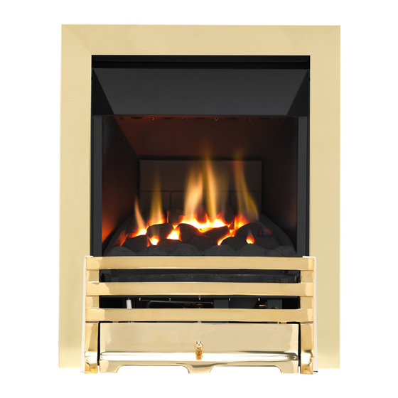
eko 4010/4015
eko 4020/4025
high efficiency fuel effect gas fire
manual control - slide control
IN THE UK ALWAYS USE A GAS SAFE REGISTERED ENGINEER TO INSTALL, REPAIR OR SERVICE THIS APPLIANCE
Advertisement
Table of Contents

Subscribe to Our Youtube Channel
Related Manuals for Ekofires eko 4010


Summary of Contents for Ekofires eko 4010
- Page 1 Country(s) of destination - GB/IE GB IE BS7977-1 : 2009 KM579168 eko 4010/4015 eko 4020/4025 high efficiency fuel effect gas fire manual control - slide control IN THE UK ALWAYS USE A GAS SAFE REGISTERED ENGINEER TO INSTALL, REPAIR OR SERVICE THIS APPLIANCE...
- Page 2 4010 eko 4020 Manufactured by : Focal Point Fires plc. Please note : Except where otherwise stated, all rights, including copyright in the Christchurch, Dorset BH23 2BT text, images and layout of this booklet is owned by Focal Point Fires plc. You are Tel: 01202 588 638 Fax: 01202 588 639 www.ekofires.co.uk...
-
Page 3: Table Of Contents
GB IE I N S T A L L A T I O N I N S T R U C T I O N S Section Contents Page No. Section Contents Page No. Important Notes Fitting the Burner Appliance Data Final Assembly, Testing and Commissioning Installation Requirements Spark Gap... -
Page 4: Appliance Data
GB IE 2.0 APPLIANCE DATA Inlet/Operating Max Energy Input (kW) Min Energy Input (kW) Destination Pressure (±2.0 mbar) Control Type Countries Gross Gross G20 G25 3.15 Manual GB/IE 3.15 Slide GB/IE Specifications Manual Control Models Slide Control Models Efficiency 90% (net), 81% (gross) 90% (net), 81% (gross) NOx Class Pilot Energy Input... -
Page 5: Debris Collection Space
GB IE 4.0 SITE REQUIREMENTS (continued) This appliance requires a natural draught flue system which may be one of the following; 225mm x 225mm (9in x 9in) brick or stone. 125mm (5in) minimum diameter lined brick or stone. 125mm (5in) minimum diameter twin wall flue conforming to BS 715. Pre-cast block flue complying with BS 1289 or BS EN 1858. -
Page 6: Ventilation
GB IE 5.0 VENTILATION No purpose provided ventilation is normally required for this appliance. The requirements of other appliances oper- ating in the same room or space must be taken into consideration when assessing ventilation. If spillage is detected when commissioning the appliance, then amongst other problems there may be insufficient nat- ural ventilation for correct operation of the flue. -
Page 7: Preparing The Appliance
GB IE 8.0 PREPARING THE APPLIANCE Figure 3 The fireplace opening and environment must be in compliance with specifications laid down in the appropriate sections of these instructions. Remove the appliance from it’s carton as described previously and stand upon a dust sheet or similar. Place the decorative frame, coals, ceramics and fixings safely to one side. -
Page 8: Cable Fixing
GB IE 8.3 CABLE FIXING Thread both tensioning cables through the holes at Figure 8 Cable Route the top of the firebox, both eyelets, and back through 2. Hold tensioner steady the lower holes in the firebox in the positions indicat- ed in figure 7. -
Page 9: Final Assembly
GB IE 9.3 FINAL ASSEMBLY Refit the glass panel ensuring that the unsupported edge of the glass is facing downwards. Take care not to damage the ceramic fuel bed when fitting. Secure using four M6 screws previously removed. Now fit the hood. This is provided sepa- rately. -
Page 10: Setting Pressure
GB IE 9.6 SETTING PRESSURE Control Type Test point location Manual Shown in figure 17 Slide Left hand side of burner Release the pressure test point screw, and attach a pressure gauge. Light the fire on the HIGH setting. To commission the appliance, the operating pressure must be in accordance with the figures stat- ed in section 2.0 of these instructions. -
Page 11: Briefing The Customer
GB IE 10.0 BRIEFING THE CUSTOMER All instructions must be handed to the user for safekeeping. Show the customer how to light and control the fire. After com- missioning the appliance, the customer should be instructed on the safe use of the appliance and the need for regular servic- ing. -
Page 12: Troubleshooting Guide
GB IE 11.5 REMOVING THE FIREBOX Remove the burner tray as described in section 11.2. Protect the hearth from potential damage. Unroll the coiled tensioner cables from the rear of the firebox. Remove the secur- ing nipples and tensioner adjusters. The firebox is now released from the opening and can be slid outward onto the hearth. Inspect the fireplace opening for debris and if excessive rectify the flue before proceeding further. - Page 13 GB IE U S E R S I N S T R U C T I O N S Section Contents Page No. Important Notes Firefront Clearances To Combustibles Servicing Ventilation Operating The Appliance - Manual Control Models Operating The Appliance - Slide Control Models Flue Spillage Monitoring System Cleaning Fuel Bed Layout...
- Page 14 GB IE 4.0 SERVICING The fire and flue should be checked on an annual basis to ensure all of the product of combustion are entering the flue and that there is no excessive build up of soot. The frequency of service will depend on usage, but MUST be carried out at least once annually.
- Page 15 GB IE 9.0 FUEL BED LAYOUT Figure 3 1. Remove the ceramic components from their pro- tective packaging, and place the brick panel against the rear of the firebox.Place the ceramic combustion matrix onto the burner. 2. Place the moulded coal piece marked on the underside ‘A’...
- Page 16 GB IE 10.0 CHANGING THE BATTERY (SLIDE CONTROL MODELS) Ensure appliance is off and cool. The battery is located in the front of the ignition unit, on the right hand side of the burner (shown in figure 8). Unscrew the battery holder cap. Insert 1 x ‘AA’...
Need help?
Do you have a question about the eko 4010 and is the answer not in the manual?
Questions and answers
Gas Fire not starting. Battery changed at service. No clicking sound when lever pressed down and no spark.
If the Ekofires eko 4010 gas fire does not start and there is no clicking sound or spark when the lever is pressed, possible issues include:
- No gas supply: Check that the gas isolators are open and the gas supply is turned on.
- Pipework blockage: Clean out any blockages in the gas pipes.
- Air in the gas line: Purge the gas supply to remove air or wait longer for air to clear.
- Spark earthing to metalwork: Reset the spark gap correctly.
- Blocked pilot: Clean the pilot internally.
If none of these resolve the issue, further inspection by a qualified technician is recommended.
This answer is automatically generated