
Subscribe to Our Youtube Channel
Related Manuals for Ekofires eko 2050


Summary of Contents for Ekofires eko 2050
- Page 1 All instructions must be handed to user for safekeeping Revision A - 06/09 Country(s) of destination - GB/IE eko 2050 fuel effect gas fire...
-
Page 2: Installation Instructions
INSTALLATION INSTRUCTIONS Eko 2050 Preliminary Notes Before Installation This appliance is an Inset Decorative Fuel Effect appliance that provides radiant warmth utilising the latest type burner technology. The fire is designed to fit various types of fireplaces and natural draught flues as listed in the Installation Requirements.The appliance must be installed by a competent... -
Page 3: Table Of Contents
Page No. Section Section Contents Contents Page No. Important Notes 11.0 Testing & Commissioning 12.0 Appliance Data Operating the fire (manual control) 12.1 Installation Requirements Operating the fire (remote control) Site Requirements 13.0 Spark Failure Ventilation 14.0 Setting Pressure 15.0 Unpacking the Appliance Flue Spillage monitoring system 16.0... -
Page 4: Appliance Data
APPLIANCE DATA Manual control models Remote control models Gas Group G20 Natural Gas CAT I2H G20 Natural Gas CAT I2H Inlet Pressure 20 mbar (+/- 2.0mbar) 20 mbar (+/- 2.0mbar) Max Energy Input (gross) 6.8 kW 6.8 kW Min Energy Input (gross) 3.5 kW 3.5 kW Pilot Energy Input (gross) -
Page 5: Site Requirements
SITE REQUIREMENTS The fireplace opening should be inspected and repairs made where necessary. Any chair brick may be left in place. The opening WIDTH and HEIGHT dimensions should be between 405mm and 440mm wide, and 565mm to 575mm high. Opening DEPTH should be 220mm or greater. Opening DEPTHS include any plaster or infill pan- els which form part of the installation. -
Page 6: Ventilation
SITE REQUIREMENTS (continued) Any type of fire surround used with this appliance must be adequately sealed to the wall and floor. A combustible shelf may be fixed to the wall above the fire, providing that it complies with the dimensions given below. Maximum depth of shelf Minimum distance from finished hearth surface to underside of shelf... -
Page 7: Installation Into A Chairbrick
INSTALLATION INTO A CHAIRBRICK Note: Ensure that the gas supply is isolated before commencing installation of the appliance. Smoke test the flue to ensure proper draw and that there are no leaks present. Locate the gas supply point. This appliance is suitable for all gas connections, including those concealed behind the opening. -
Page 8: Operating The Fire (Remote Control)
12.0 OPERATING THE FIRE (manual control models) - continued To achieve the HIGH setting, push the control knob in slightly and continue turning anti-clockwise to the high (large flame) position. The main burner should light after a few seconds. To decrease the setting to LOW, turn the control knob clockwise to the low setting. To turn to the PILOT position from the HIGH or LOW positions, press the control knob in, and return to the pilot position and release. -
Page 9: Setting Pressure
14.0 SETTING PRESSURE Remove the screw from the pressure test point. The pressure test point is situated on the main injector pipe next to the pilot. The setting pressure should be in accordance with the figures stated on page 2 of these instructions. The fire is factory set to achieve these pressures, and any signif- icant variation could indicate a supply problem. -
Page 10: Briefing The Customer
16.0 TESTING FOR SPILLAGE - continued All the smoke should be drawn away up the flue. Any smoke returning into the room indicates that spillage is occurring. If the initial spillage test fails, run the fire for a further 10 minutes and repeat the test. -
Page 11: Dismantling The Burner Tray
18.2 DISMANTLING THE BURNER TRAY Remove the tray as previously described. The pilot unit can be removed by undoing the tubing nut, the thermocouple nut on the rear of the valve, lint arrestor, two securing screws, and lifting away. Remove the tubing nut from the valve end of the pilot pipe, and blow through to dislodge any debris that may be present. -
Page 12: User Instructions
USER INSTRUCTIONS Section Contents Page No. Important Notes Firefront Clearances to Combustibles Ventilation Fuel Bed Layout (Coal models) Fuel Bed Layout (Pebble models) Fuel Bed Layout (Log models) Operating Instructions (Manual models) Operating Instructions (Remote models) Flue Spillage Monitoring System Cleaning Servicing 10.0... -
Page 13: Clearances To Combustibles
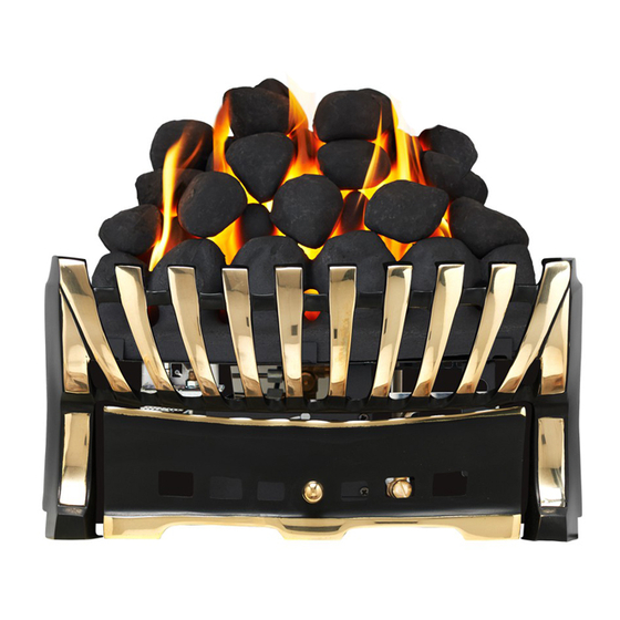
FIREFRONT This fire is supplied with a particular style of firefront. Use of the firefront will ensure an adequate airflow under the fuelbed for the correct functioning of this appliance. Compliance with safety standards cannot be guaranteed if another style of front is used. CLEARANCES TO COMBUSTIBLES A combustible shelf may be fixed to the wall above the fire, providing that it complies with the dimensions given below. - Page 14 FUEL BED LAYOUT (coal effect models) - continued 3. Open the bag of 16 moulded coals. All of the coals are the same. Take five coals and place them as shown. Care should be taken to ensure that the coals bridge the gap between the front coal and the four coal supports at the front of the matrix.
- Page 15 FUEL BED LAYOUT (pebble effect option)- continued 2. Open the bag of 16 ceramic pebbles. All of these pebbles are the same size. Take five pebbles and place them as shown. Care should be taken to ensure that the pebbles bridge the gap between the front strip and the four supports at the front of the matrix.
-
Page 16: Operating Instructions
FUEL BED LAYOUT (Log effect option) continued 2. Open the bag of 9 moulded ceramic logs. All of the logs except two are the same. Take the largest log (numbered 16) and place it as shown. Care should be taken to ensure that the orientation is correct and the log fits snugly into its position. - Page 17 OPERATING INSTRUCTIONS (manual control models) - continued When the pilot lights after the spark, keep the knob depressed for approximately ten seconds. Now release the knob and the pilot should stay alight. If not, repeat ignition. If the pilot is extin- guished during use, wait three minutes before repeating the ignition procedure.
-
Page 18: List Of Spares
FLUE SPILLAGE MONITORING SYSTEM - continued If pilot disturbance is not the cause, then the ODS safety system may be in operation. Switch the appliance OFF, call in your installer to check the flue and ventilation and carry out any remedial work required.
Need help?
Do you have a question about the eko 2050 and is the answer not in the manual?
Questions and answers