Table of Contents
Advertisement
Quick Links
INSTALLATION & USER INSTRUCTIONS
Christchurch, Dorset BH23 2BT
Tel: 01202 588 638
Fax: 01202 499 639
www.ekofires.co.uk
e-mail: sales@ekofires.co.uk
PLEASE NOTE: EKO 1060/1070 ELECTRIC FIRES MAY BE SUPPLIED WITH DIFFERENT FRET & FRAME
Please note : Except where otherwise stated, all rights,
including copyright in the text, images and layout of this
booklet is owned by Focal Point Fires plc. You are not per-
mitted to copy or adapt any of the content without the
prior written permission of Focal Point Fires plc.
LED ELECTRIC FIRE
MODELS COVERED BY THESE INSTRUCTIONS
1060 LED INSET ELECTRIC FIRE
1070 LED REFLECTIONS INSET ELECTRIC FIRE
FRET AND FRAME OPTIONS AVAILABLE
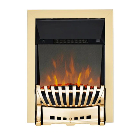
MODEL SHOWN: EKO 1060 LED INSET ELECTRIC FIRE
THAN SHOWN
All instructions must be handed to the user
1
GB IE
for safekeeping.
Revision B - 01/14
2014 Focal Point Fires plc.
'
Advertisement
Table of Contents

Related Manuals for Ekofires 1060 LED INSET ELECTRIC FIRE


Summary of Contents for Ekofires 1060 LED INSET ELECTRIC FIRE
- Page 1 FRET AND FRAME OPTIONS AVAILABLE www.ekofires.co.uk e-mail: sales@ekofires.co.uk MODEL SHOWN: EKO 1060 LED INSET ELECTRIC FIRE PLEASE NOTE: EKO 1060/1070 ELECTRIC FIRES MAY BE SUPPLIED WITH DIFFERENT FRET & FRAME THAN SHOWN All instructions must be handed to the user...
-
Page 2: Appliance Data
I N S TA L L AT I O N & U S E R I N S T R U C T I O N S GB IE Section Contents Page No. Section Contents Page No. Preliminary Notes Removing the appliance spacer frames Appliance Data Fitting The Decorative Frame And Front 5 Installation Requirements... -
Page 3: Unpacking The Appliance
3.0 INSTALLATION REQUIREMENTS - GB IE CONTINUED DO NOT site in a position where curtains or drapes could cover the appliance. site in a position where other soft materials could cover e.g. below a coat rack. site behind an opening door where mechanical impact/damage could occur. site where the supply cable would become a trip hazard. - Page 4 6.0 INSTALLING THE APPLIANCE - CONTINUED GB IE Method 2 Screw fixings. Using suitable fixings for your wall or surround, mark the centre of your opening and measure 227mm to the left and then again to the right. From there measure from the floor 304mm up the wall.This will be the centre of the screw.
- Page 5 7.0 REMOVING THE APPLIANCE SPACER FRAMES-CON GB IE Step 3: Remove the outer spacer frame. Step 4: To remove the second spacer repeat the same method used in steps 1, 2 & 3. 8.0 FITTING THE DECORATIVE FRAME AND FRONT The appliance may be supplied with a decorative frame in a variety of finishes.
-
Page 6: Operating The Appliance
9.0 OPERATING THE APPLIANCE GB IE The heater is operated via the use of two switches, one situated on the left hand side of the canopy and one on the right. The switch on the left hand side towards the top, marked (0I), controls the main power to the appliance and switches on the LED display panel. The next switch on the right hand side, with a “single bar”... - Page 7 EKO Fires, 3G Service Department, Reid Street, Christchurch, Dorset, BH23 2BT. Alternatively email: service@ekofires.co.uk or fax. 01202 499326. Details required: 1. Name, full address including post code and contact telephone number.
Need help?
Do you have a question about the 1060 LED INSET ELECTRIC FIRE and is the answer not in the manual?
Questions and answers