Table of Contents
Advertisement
User Guide IM/NAV6S/SS–EN Rev. E
Navigator 600 Silica
Single-stream
Introduction
The Navigator 600 Silica is an advanced colorimetric
analyzer used to measure the level of silica in the steam
water cycle in power plants.
This manual applies only to Navigator 600 Silica model
numbers AW641/xxxxx9xx
The Company
We are an established world force in the design and manufacture of measurement products for industrial process control, flow
measurement, gas and liquid analysis and environmental applications.
As a part of ABB, a world leader in process automation technology, we offer customers application expertise, service and support
worldwide.
We are committed to teamwork, high quality manufacturing, advanced technology and unrivalled service and support.
The quality, accuracy and performance of the Company's products result from over 100 years experience, combined with a
continuous program of innovative design and development to incorporate the latest technology.
Advertisement
Table of Contents
Troubleshooting

Related Manuals for ABB Navigator 600 Silica


Summary of Contents for ABB Navigator 600 Silica
- Page 1 Single-stream As a part of ABB, a world leader in process automation technology, we offer customers application expertise, service and support worldwide. We are committed to teamwork, high quality manufacturing, advanced technology and unrivalled service and support.
- Page 2 Configuration Level Common Configuration Measurement Logging Level* Current Outputs Alarm Relays Logging Not enabled from: Communications Audit Log Alarm Event Log *This level cannot be accessed from 'Configuration /Logging'...
-
Page 3: Table Of Contents
Navigator 600 Silica Single-stream Contents Contents 1 Safety ................3 5 Configuration ..............23 Health & Safety ............3 Front Panel Controls ..........23 Electrical Safety – CEI / IEC 61010-1:2001-2 ... 3 Navigation and Editing ........... 23 Symbols – CEI / IEC 61010-1:2001-2 ...... 4 5.2.1 Text Editing .......... - Page 4 Navigator 600 Silica Single-stream Contents 9 Logging ................53 Appendix D – Online Help ..........79 SD Cards ...............54 Reset Archiving ............55 Appendix E – Web Server ..........80 File Viewer ..............55 Stream Values ............81 Archive File Types ...........56 Reagent & Solution Levels ........81 Data Files ...............56...
-
Page 5: Safety
Navigator 600 Silica Single-stream 1 Safety 1 Safety Information in this manual is intended only to assist our customers in the efficient operation of our equipment. Use of this manual for any other purpose is specifically prohibited and its contents are not to be reproduced in full or part without prior approval of the Technical Publications Department. -
Page 6: Symbols - Cei / Iec 61010-1:2001-2
Navigator 600 Silica Single-stream 1 Safety 1.3 Symbols – CEI / IEC 61010-1:2001-2 One or more of the following symbols may appear on the equipment labelling: This symbol indicates the presence of devices Protective earth (ground) terminal. sensitive to electrostatic discharge and indicates that care must be taken to prevent damage to them. -
Page 7: Product Recycling Information
Note. The following only applies to European customers. ABB is committed to ensuring that the risk of any environmental damage or pollution caused by any of its products is minimized as far as possible. The European Waste Electrical and Electronic Equipment (WEEE) Directive (2002/96/EC) that came into force on August 13 2005 aims to reduce the waste arising from electrical and electronic equipment;... -
Page 8: Safety Conventions
Other than the serviceable items listed in Appendix H, page 86, none of the instrument's components can be serviced by the user. Only ABB personnel or ABB-approved representatives are authorized to attempt repairs to the system and only ABB-approved components must be used. Any attempt at repairing the instrument in contravention of these principles could cause damage to the instrument and injury to the person carrying out the repair. -
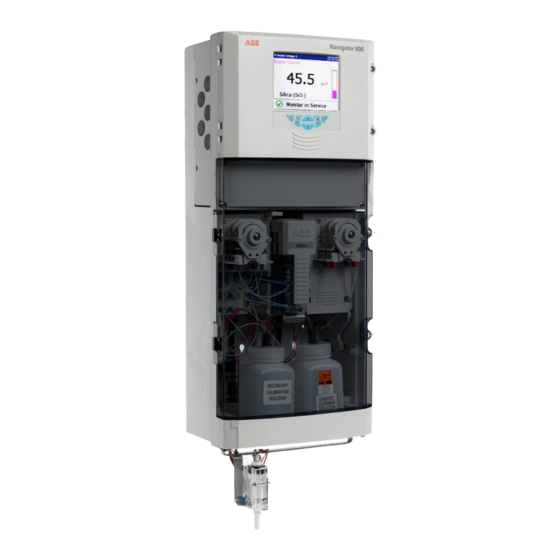
Page 9: Overview
During see Appendix F, page 84. operation, a signal generated from the sensing system is *For information about reagent solutions, contact your local ABB converted by the analyzer into data and this information is presented on the display. -
Page 10: Principle Of Operation
Navigator 600 Silica Single-stream 3 Principle of Operation 3 Principle of Operation 3.1 Chemical Principle The chemical method used by the analyzer is based on the 6. The reduction solution is added to reduce the yellow reaction of ammonium molybdate with silicate species, under... - Page 11 Navigator 600 Silica Single-stream 3 Principle of Operation Reacted sample to optical unit Temperature controlled at 45 ° C (167F) Production of blue molybdosilicic acid complex 1 Minute 0.8 to 1.0 pH providing reducing conditions Reduction Solution to stop formation of yellow complex...
-
Page 12: Liquid Handling
Navigator 600 Silica Single-stream 3 Principle of Operation 3.2 Liquid Handling Referring to Fig. 3.2: The sample enters the analyzer via a constant head unit situated at the bottom of the analyzer. The constant head unit is fitted with an 'Out of Sample' switch that detects a loss of sample. - Page 13 Navigator 600 Silica Single-stream 3 Principle of Operation To Drain Peristaltic Pump Peristaltic Pump Cuvette Rear Pump Capstan Front Pump Capstan Front Pump Capstan Rear Pump Capstan To Drain Calibration Solenoid Valve Cleaning Solution Solenoid Valve Filter Constant-head Unit Cleaning...
-
Page 14: Out Of Sample
Navigator 600 Silica Single-stream 3 Principle of Operation 3.3 Out of Sample If the analyzer detects that the sample is lost (via the out of sample switch), the analyzer shuts down automatically to prevent air being drawn into the analyzer and to conserve reagents. -
Page 15: Installation
Navigator 600 Silica Single-stream 4 Installation 4 Installation 4.1 Accessories The following accessories are supplied with the analyzer: 4 x 2.5 l reagent bottle and cap 1 x 500 ml cleaning solution bottle and cap 1 x 500 ml standard solution bottle and cap... -
Page 16: Sampling Requirements
Navigator 600 Silica Single-stream 4 Installation 4.2 Sampling Requirements 4.3 Location The sampling point must be as near as possible to the analyzer For general location requirements refer to Fig. 4.1. Install indoors and must provide a thoroughly mixed, representative sample. -
Page 17: Reagent Bottle Location
Navigator 600 Silica Single-stream 4 Installation 4.4 Reagent Bottle Location 4.4.1 Behind Mounting Plate or Wall 4.4.2 To Side of Analyzer To prevent reagent flow due to gravity during maintenance, ensure top of reagent bottles are below the level of the pumps. -
Page 18: Mounting
Navigator 600 Silica Single-stream 4 Installation 4.5 Mounting 4.5.1 Mounting Dimensions Dimensions in mm (in.) 314 (12.36) 182 (7.16) 271 (10.67) 122 (4.80) 280 (11.02) 150 (5.90) 560 (22.05) 300 (11.81) Reagent bottles mounted on optional brackets (two bottles per bracket) Example –... -
Page 19: Mounting The Analyzer
Navigator 600 Silica Single-stream 4 Installation 4.5.2 Mounting the Analyzer 4.5.3 Mounting the Reagent Shelf (Optional) Dimensions in mm (in.) All Dimensions in mm (in.) (6.59) (4.48) (6.59) (3.23) (2.95) (3.00) (2.95) (20.7) (3.18) Fig. 4.7 Reagent Mounting Shelf (option) If used, mount the reagent shelve(s) no more than 1 m (3.3 ft.) -
Page 20: Electrical Connections
Navigator 600 Silica Single-stream 4 Installation 4.6 Electrical Connections Warning. The analyzer is not fitted with a switch therefore an isolation device such as a switch or circuit breaker conforming to local safety standards must be fitted to the final installation. It must be fitted in close proximity to the analyzer within easy reach of the operator and must be marked clearly as the disconnection device for the analyzer. -
Page 21: Connections Overview
Navigator 600 Silica Single-stream 4 Installation 4.6.1 Connections Overview Note. Field wiring terminal screws must be tightened to a torque of 0.6 to 0.8 Nm (5 to 7 lbf.in). Socket for Optional Digital Communications Out of Service Hold/Maintenance Relay Relay... -
Page 22: Accessing And Making Connections
Navigator 600 Silica Single-stream 4 Installation 4.6.2 Accessing and Making Connections Note. Cable entry holes are located on both sides of the enclosure. Application board connection labels for the terminal blocks are identified in Fig. 4.8, page 19. -
Page 23: Ethernet Connections
Navigator 600 Silica Single-stream 4 Installation 4.6.3 Ethernet Connections 4.6.4 Alarm Relay Contact Protection and Interference Suppression Warning. Remove all power from supply, relay and any NC C NO powered control circuits and high common mode voltages Relay Contacts before accessing or making any connections. -
Page 24: Preparing The Analytical Section
Navigator 600 Silica Single-stream 4 Installation 4.7 Preparing the Analytical Section 4.7.1 Connecting Sample Inlet and Drain Line(s) 4.7.2 Connecting the Contaminated Drain Tube 9 mm ( in.) PVC Tubing 6 mm ( in.) PVC Tubing 9 mm ( in.) PVC Tubing Fig. -
Page 25: Configuration
Navigator 600 Silica Single-stream 5 Configuration 5 Configuration 5.1 Front Panel Controls 5.2 Navigation and Editing Depending on the type of field to be edited, the software provides a variety of methods for entering values. 5.2.1 Text Editing If the field to be edited requires text, a keyboard is displayed: Fig. -
Page 26: Other Methods Of Editing
Navigator 600 Silica Single-stream 5 Configuration 5.2.3 Other Methods of Editing 5.2.4 Menus There are several other methods of editing, for example: Press to open the menu and use the keys to select a menu item. Press to open the menu item:... - Page 27 Navigator 600 Silica Single-stream 5 Configuration Invalid Password Entered Displayed only if 'Security system' parameter is set to Displayed only if 'Security 'Basic' – see on-line help system' parameter is set to system 'Advanced' – see on-line help system Configuration Level...
-
Page 28: Common
Navigator 600 Silica Single-stream 5 Configuration 5.3 Common There are nine Common Configuration screens: 5.3.1 Setup Fields Description Lists the available languages. Language A new language selection does not take effect until the configuration is saved. The analyzer tag text is displayed in the top-left corner of the operator views. Up to 20 characters can be used. -
Page 29: Time
Navigator 600 Silica Single-stream 5 Configuration 5.3.3 Time Fields Description Warning. Changing the time can result in the permanent loss of data. Once it is changed a warning Date and Time is displayed stating that recording is disabled until the configuration has been saved. -
Page 30: Security
Navigator 600 Silica Single-stream 5 Configuration 5.3.4 Security 'User 1' is the System Administrator and is the only user that has access to the 'Security type' parameter. User 1 details cannot be changed by any other user. There are two types of security: ... - Page 31 Navigator 600 Silica Single-stream 5 Configuration Fields Description A page opens with two fields: Security system – toggles between 'Basic' and 'Advanced'. Security type Configuration security – toggles between 'Password protected' and 'Internal switch protected'. Set access to the 'Calibration & Maintenance' and 'Logging' menus.
-
Page 32: User
Navigator 600 Silica Single-stream 5 Configuration 5.3.5 User Fields Description If 'Security system' is set to 'Basic' this tab lists the four users, User 1 to User 4. Selecting a user opens a new page with two fields: Name – the user’s name, up to 20 characters. -
Page 33: Messages
Navigator 600 Silica Single-stream 5 Configuration 5.3.6 Messages Fields Description Up to 24 messages can be defined to indicate a particular event or action has occurred. These are Messages displayed on the chart when the relevant annotation is enabled. IM/NAV6S/SS–EN Rev. E... -
Page 34: Measurement
Navigator 600 Silica Single-stream 5 Configuration 5.4 Measurement There are three tabs in the 'Measurement' screen: 5.4.1 Setup Fields Description The display units for silica concentration. Three options are available: Display Units µg/l µg/kg The reaction temperature range is 37 to 50 °C (98 to 122 °F) in 0.1 °C (0.18 °F) increments. The analyzer is optimized to run at a reaction temperature of 45 °C (113 °F). -
Page 35: Streams
Navigator 600 Silica Single-stream 5 Configuration 5.4.2 Streams Fields Description The page opens with three fields: Stream 1 Tag – adds an identification for the stream. Range Low – sets the low range value (0 to 5000 ppb). -
Page 36: Alarm Relays
Navigator 600 Silica Single-stream 5 Configuration 5.5 Alarm Relays Concentration Hysteresis Trip Point Hysteresis Concentration Concentration Alarm On Alarm On Alarm Off Alarm switches Alarm switches off automatically off automatically High Alarm Action Low Alarm Action Fig. 5.3 High / Low Process Alarms... - Page 37 Navigator 600 Silica Single-stream 5 Configuration There are six tabs in the Alarm Relays screen, one for each alarm: Fields Description Each of the six alarms can be configured independently to one of the following sources: None – no other fields are visible Alarm Source ...
-
Page 38: Current Outputs
Navigator 600 Silica Single-stream 5 Configuration 5.6 Current Outputs There are six tabs in the Current Outputs screen, one for each output: Fields Description The 'Output Source' field has several options: Output Source None. No other fields are visible ... -
Page 39: Logging
Navigator 600 Silica Single-stream 5 Configuration 5.7 Logging There are three tabs in the 'Logging' screen: 5.7.1 Recording Fields Description The frequency (up to 720 minutes) at which stream data is recorded to the analyzer's internal Sample Rate memory and the SD card (if fitted). -
Page 40: Archive
Navigator 600 Silica Single-stream 5 Configuration 5.7.3 Archive Used to configure the data that is to be recorded on the SD card – see Section 9, page 53. When external archive media contains approximately 300 files, its read / write performance becomes too slow, archiving is stopped... -
Page 41: Communications
Navigator 600 Silica Single-stream 5 Configuration 5.8 Communications There are three tabs in the I/O modules screen: 5.8.1 Ethernet Configures the way that the analyzer can be accessed via an Ethernet network – see Appendix E, page 80. Note. Changes to the 'IP-address', 'Subnet mask' and 'Default Gateway' parameters are implemented only after the analyzer has been restarted. -
Page 42: Email 1 And Email 2
Navigator 600 Silica Single-stream 5 Configuration 5.8.2 email 1 and email 2 The analyzer can be configured to send emails to a maximum of 6 recipients in response to certain events. The addressees can all subscribe to the same SMTP server or the analyzer can be configured to send emails via 2 different SMTP servers to a maximum of 3 addressees per server. -
Page 43: Start-Up
Navigator 600 Silica Single-stream 6 Start-up 6 Start-up 6.1 Commissioning the Analyzer 7. Purge the zero calibration line and the secondary and Warning. clean solution lines as follows: Protective eye wear and protective hand wear must be worn a. Press the key, select 'Calibration &... -
Page 44: Performing A Baseline Calibration
Navigator 600 Silica Single-stream 6 Start-up 6.2 Performing a Baseline Calibration Note. Before starting the initial Baseline calibration, it is important to check the reagent lines are fully purged and there is no air flowing through the reaction block. -
Page 45: Calibration & Maintenance
Navigator 600 Silica Single-stream 7 Calibration & Maintenance 7 Calibration & Maintenance Invalid Password Password Required (if set) Valid Password No Password Required Setup Calibration / Clean – see Section 7.4, page 46 Calibration – see Section 7.5, page 47 Solutions Replacement –... -
Page 46: Zero Calibration
Navigator 600 Silica Single-stream 7 Calibration & Maintenance 7.1 Zero Calibration During the zero calibration the sample is diverted from its normal flowpath by the Auto Zero valve into the second mixing stage. The pH value at this point is too low to allow the silica-molybdate reaction to take place, consequently a solution equivalent to a zero silica concentration is produced. -
Page 47: Secondary Calibration
Navigator 600 Silica Single-stream 7 Calibration & Maintenance 7.2 Secondary Calibration If the response is not perfect, compensation is applied to make 100 % the readings correct and the resulting Calibrating factor provides Theoretical Response – an indication of how much compensation is required – see Calibration Factor 1.0... -
Page 48: Setup Calibration / Clean
Navigator 600 Silica Single-stream 7 Calibration & Maintenance 7.4 Setup Calibration / Clean Enables scheduled calibration and cleaning. Fields Description The automatic calibration schedule for the analyzer. A dialog box is displayed with the following options: Zero Frequency – the frequency zero calibrations are performed (off to 7 days). -
Page 49: Calibration
Navigator 600 Silica Single-stream 7 Calibration & Maintenance 7.5 Calibration Enables manual calibrations to be performed. Fields Description The value of the secondary calibration solution used (10 to 5000 ppb) – see Appendix A.2, page 64. Secondary Calibration Value Note. This is the same value used in the 'Setup Calibration / Clean' options. Changing the value here also changes the value in the 'Setup Calibration / Clean' options. -
Page 50: Maintenance
Navigator 600 Silica Single-stream 8 Maintenance 8 Maintenance 8.1 Scheduled Maintenance Warning. 8.1.1 Chemical Solutions Ensure personal protective equipment (PPE) such as Reagent, calibration and cleaning solutions are necessary to gloves and eye protection are worn during any maintain the analyzer in operation. Use the bottles supplied. If... -
Page 51: Solution Replacement
Navigator 600 Silica Single-stream 8 Maintenance 8.1.2 Solution Replacement 8.1.3 Annual Service The analyzer has predictive capability that notifies when the The analyzer is taken offline and the pumps are stopped when solutions require changing. For details of the reagent, clean and an annual service is in progress. - Page 52 Navigator 600 Silica Single-stream 8 Maintenance Referring to Fig. 8.1: 11. Ensure the tubing is aligned correctly over the rollers. 1. Unlock catch , use handle to slide the analytical 12. Refit the platens and pump end plate section forward and lock it into place using catch Note.
-
Page 53: Periodic Maintenance
Navigator 600 Silica Single-stream 8 Maintenance 8.2 Periodic Maintenance 8.2.1 Sample Filter Replacement The sample filter prevents large particles from entering the wet 8.2.2 Reagent Tube Filter Replacement Each reagent tube has an integral filter fitted into the sinker. section. Filter longevity is related to the level of particulates in the samples. -
Page 54: Dc Fuse Replacement
Navigator 600 Silica Single-stream 8 Maintenance 8.3 DC Fuse Replacement 8.4 Manual Test Settings This function is used to aid troubleshooting – see Appendix C, page 74. Caution. Only use replacement fuse: 12.5 A 125 V DC Type T, SCHURTER, Model SPT 5 x 20 Series The analyzer is taken offline when Manual Test Settings are used. -
Page 55: Logging
When handling the card take care not to touch any exposed metal contacts. Note. ABB's DataManager software can be used to store and view data archived from the analyzer. Note. -
Page 56: Sd Cards
Navigator 600 Silica Single-stream 9 Logging 9.1 SD Cards To access the SD Card: There are two methods of archiving to an SD card: 1. Ensure the analyzer is offline. An SD card is kept in the analyzer 2. Use a large flat-headed screwdriver to release the two... -
Page 57: Reset Archiving
Navigator 600 Silica Single-stream 9 Logging When an SD card is inserted and there is <1 day (Binary format) 9.2 Reset Archiving or <1 hour (Text format) of data in internal memory, a dialog box If 'Reset Archiving' is selected, all data in the internal memory is is displayed giving the user the choice of putting the media re-archived to external media. -
Page 58: Archive File Types
Navigator 600 Silica Single-stream 9 Logging 9.4 Archive File Types 9.5.1 Data Filenames Data files can be configured to contain data gathered over a All archive files created by the analyzer are assigned filenames predefined period of time ('New File Interval') – see automatically. -
Page 59: Log Files
Navigator 600 Silica Single-stream 9 Logging 9.5.2 Log Files 9.5.4 Filename Examples The 'Alarm Event' and 'Audit' logs are archived into individual New file interval set to Hourly, Filename tag set to Process files. The filenames are formatted as follows: Group 1;... -
Page 60: Chart Functions
Navigator 600 Silica Single-stream 10 Chart Functions 10 Chart Functions Historical Review – see Section 10.1 Operator Messages – see Section 10.2 Chart Annotation – see Section 10.3 Screen Interval – see Section 10.4 Scales – see Section 10.5 Trace Select – see Section 10.6 Fig. -
Page 61: Scales
Navigator 600 Silica Single-stream 11 Alarm Acknowledge 10.5 Scales 11 Alarm Acknowledge Selects the scale to be used – see Section 5.4.2, page 33. To acknowledge a particular alarm, use the keys to highlight it in the menu and press the key. -
Page 62: Diagnostic Information
Navigator 600 Silica Single-stream 12 Diagnostic Information 12 Diagnostic Information Ensure that a note is made of all the information in the 12.2 System Information Diagnostic screens when contacting the Company regarding The system information screen provides details regarding the spares or enquires. -
Page 63: Valves And Pumps Status
Navigator 600 Silica Single-stream 12 Diagnostic Information 12.4 Valves and Pumps Status 12.5 Statistics Displays the status of the wet section valves and pumps. Displays the highest, lowest and mean values of the sample stream since the analyzer was either switched or the values were reset. -
Page 64: Specification
Navigator 600 Silica Single-stream 13 Specification 13 Specification Silica Measurement Display Range Color*, passive matrix, liquid crystal display (LCD) with built-in backlight and brightness adjustment Fully user programmable 0 to 5000 ppb SiO minimum range 0 to 50 ppb Diagonal display area 144 mm (5.7 in.) - Page 65 Navigator 600 Silica Single-stream 13 Specification Environmental Data Alarms / Relay Outputs Ambient Operating Temperature One per unit: 5 to 45 ºC (41 to 113 ºF) out-of-service alarm relay Sample Temperature calibration in progress alarm relay 5 to 55 ºC (41 to 131 ºF) ...
-
Page 66: Appendix A - Solutions
The bottles and c. Store the solution in a polythene bottle. associated tubing are color-coded to identify each reagent. Contact your local ABB representative for further information about reagent solutions. 3. From sodium metasilicate a. -
Page 67: Cleaning Solution
Navigator 600 Silica Single-stream Appendix A – Solutions A.3 Cleaning Solution A.3.1 Regular Cleaning Solution (for Automatic Cleaning Operation) It is important that the internal pipework of the analyzer is To prepare 1 liter of regular cleaning solution: cleaned using the automatic cleaning schedule – see Section 7.4, page 46. -
Page 68: Appendix B - Diagnostics And Alarms
Power the analyzer down, wait for 10 seconds and power back up. All calibrations Notes. and cleans If the error persists contact your local ABB representative. Replacement board (see Appendix H, page 88 – part number AW600065). Excessive Secondary Current in Electronics Too much current is being drawn by the system electronics in;... - Page 69 1. Check the connection labelled 'HEATER PT1000' on the and cleans Interconnection Board. 2. If the error persists, contact your local ABB representative. Reaction Block Temp. High / Low >20 °C (36 °F) above or >20 °C (36 °F) below The measured temperature is more than 20 °C (36 °F) above or...
- Page 70 1. Power the analyzer down, wait for 10 seconds and power calibrations back up. 2. If the error persists, contact your local ABB representative. Calibration Factor Too High / Low A secondary calibration failure has occurred because the calibration factor is less than or greater than the acceptable limit programmed.
- Page 71 Section 12.3, page 60. If the temperature is low, check the heater LED on the main board is lit. If it is not, contact your local ABB representative. Pre-Heat Temperature High / Low >10 °C (18 °F) but <20 °C (36 °F) above or below The measured temperature is more than 10 °C (18 °F) but less...
- Page 72 Navigator 600 Silica Single-stream Appendix B – Diagnostics and Alarms Out-of- Cal. in Cal. Hold Icon Diagnostic message Service Progress Failed Inhibits Relay Relay Relay Relay Solution Replacement Scheduled calibrations The analyzer is shut down while solution is replaced. and cleans Scheduled Secondary Cal.
- Page 73 Navigator 600 Silica Single-stream Appendix B – Diagnostics and Alarms Out-of- Cal. in Cal. Hold Icon Diagnostic message Service Progress Failed Inhibits Relay Relay Relay Relay In Purge This routine is initiated at power up and after solution replacement or an annual service.
- Page 74 Navigator 600 Silica Single-stream Appendix B – Diagnostics and Alarms Out-of- Cal. in Cal. Hold Icon Diagnostic message Service Progress Failed Inhibits Relay Relay Relay Relay Out of Cleaning Solution The cleaning solution bottle is empty. 1. Replace the cleaning solution.
-
Page 75: Audit Log And Alarm Event Log
Navigator 600 Silica Single-stream Appendix B – Diagnostics and Alarms B.2 Audit Log and Alarm Event Log The 'Audit Log' and 'Alarm Event Log' are used to display a list of events and alarms identified by icon, sequence number, date and time. -
Page 76: Appendix C - Troubleshooting
Navigator 600 Silica Single-stream Appendix C – Troubleshooting Appendix C – Troubleshooting C.1 Analyzer Malfunction For the analyzer to function correctly and to specification, the Virtually all problems with the analyzer are as a result of 1 or following conditions must be met: more of these not being correct. -
Page 77: Air In System
Navigator 600 Silica Single-stream Appendix C – Troubleshooting C.2.1 Air in System Symptom Action Air in system Check for air bubbles in the reaction block and in the tube feeding the optical unit. If bubbles are found, check if they are present in the sample line or originate from one or more of the reagents. -
Page 78: Optical System Errors
Navigator 600 Silica Single-stream Appendix C – Troubleshooting C.2.2 Optical System Errors Symptom Action Unstable mV values The optical system receives mV signals from the cuvette and cuvette reference sensors. For accurate readings both these values must be stable. Note. When viewing these readings, be aware that if the silica level in the analyzer changes gradually, the cuvette voltage also changes gradually. -
Page 79: Chemistry And Color Generation Errors
Navigator 600 Silica Single-stream Appendix C – Troubleshooting C.2.3 Chemistry and Color Generation Errors Symptom Action Reagent order For correct chemistry and color generation to take place in the reaction block area, the reagents must enter the reaction block in the correct order: 1. -
Page 80: Zero And Secondary Calibration Valve Malfunction
Navigator 600 Silica Single-stream Appendix C – Troubleshooting C.2.4 Zero and Secondary Calibration Valve Malfunction Check / Symptom Action Secondary To check the valve: calibration valve 1. Manually energize the secondary calibration valve – see Section 8.4, page 52 ('Manual Test malfunction Settings'). -
Page 81: Appendix D - Online Help
Navigator 600 Silica Single-stream Appendix D – Online Help Appendix D – Online Help Fig. D.1 Context-sensitive Help If any alarms or messages appear on the operator screen, press key to open the help at the relevant help topic. The help goes directly to the relevant topic when selected from any menu item. -
Page 82: Appendix E - Web Server
Navigator 600 Silica Single-stream Appendix E – Web Server Appendix E – Web Server Fig. E.1 Web Server Screen d Language Selection – selects the language for the web The analyzer is fitted with an ethernet card as standard and, when the appropriate configuration settings have been made, pages. -
Page 83: Stream Values
Navigator 600 Silica Single-stream Appendix E – Web Server E.1 Stream Values E.5 Statistics E.6 System Information E.2 Reagent & Solution Levels E.3 Measurement Status E.7 Logging Status E.4 Valve & Pump Status IM/NAV6S/SS–EN Rev. E... -
Page 84: Operator Messages
Navigator 600 Silica Single-stream Appendix E – Web Server E.8 Operator Messages E.9 Configuration Change or retain security configuration Select a configuration previously saved to internal storage or select a QuickStart template Change the analyzer's current date and time An 'Operator Message' is displayed on the chart view. For Note. -
Page 85: Ftp Access Via Internet Explorer
Navigator 600 Silica Single-stream Appendix E – Web Server E.11 FTP Access via Internet Explorer 3. Type the 'User name' and 'Password' and press enter. Note. FTP access requires Internet Explorer version 5.5 or The folders that are present on the analyzer are displayed. -
Page 86: Appendix F - Updating The Software
10. To upgrade the existing system software, press the approximately 5 seconds, followed by an 'ABB' splash key to start the process. (The software is transferred to the screen: analyzer in sections.) 11. Press the key as each section is installed (installation may take a few moments). -
Page 87: Appendix G - Analyzing A Grab Sample
Navigator 600 Silica Single-stream Appendix G – Analyzing a Grab Sample Appendix G – Analyzing a Grab Sample To analyze a grab sample: 1. Setup a grab sample: a. unscrew the Secondary bottle lid and remove the level sensor. b. rinse the level sensor with high purity water. -
Page 88: Appendix H - Spare Parts
Navigator 600 Silica Single-stream Appendix H – Spare Parts Appendix H – Spare Parts Warning. Spares items identified with the symbol must be fitted only by ABB personnel or an ABB-approved representative. Part No. Description Part No. Description AW601155 Annual spares kit (suitable for analyzers with... - Page 89 Navigator 600 Silica Single-stream Appendix H – Spare Parts Part No. Description Part No. Description AW600047 Pump motor and coupling AW600034 Calibration / clean / cuvette / sample select valve incl. manifold AW600046 Reaction block temperature sensor AW600710 Out of sample switch new type...
- Page 90 Navigator 600 Silica Single-stream Appendix H – Spare Parts Part No. Description Part No. Description AW600730 Bottle empty – cleaning solution / secondary AW600023 Cable gland kit calibration / zero calibration AW600731 Bottle empty – reduction ascorbic / ammonium molybdate / 1...
- Page 91 Navigator 600 Silica Single-stream Appendix H – Spare Parts Part No. Description Part No. Description AW600028 AC Transmitter (excluding Profibus card) AW600061 Secondary debubbler AW600016 DC Transmitter (excluding Profibus card) AW601720 Pre-heater assembly AW600068 Front door inc. keypad and display...
- Page 92 Navigator 600 Silica Single-stream Index Index Access Editing ................23 User Access ..............30 Email ................40 Ethernet ................39 Accessories ..............13 Alarm Relays ..............34 Alarms Fail Safe ..............35 Fail Safe ................35 Relay Contact Protection ...........21 File Viewer ............... 55 Annotation Filters ................
- Page 93 Navigator 600 Silica Single-stream Index Navigation ............... 23 Sample Filter Replacement ..........51 Sampling Requirements ..........14 Schematic ................ 8 Screen Capture .............. 26 Operation – Calibration & Maintenance ......43 Screen Interval ..............58 Operator Screen saver wait time ............ 26 Messages ..............
- Page 94 Navigator 600 Silica Single-stream Index Time ................27 Troubleshooting ..............74 Tubing Schematic ..............8 Unpacking ...............13 Updating the Software .............84 User settings ..............30 Valve Status ..............61 Web ................80 Web Server ..............80 IM/NAV6S/SS–EN Rev. E...
- Page 95 — Food & Beverage offices for details on your nearest Service and Repair Centre. — Manufacturing — Metals and Minerals — Oil, Gas & Petrochemical ABB Limited — Pulp and Paper Tel: +44 (0)1453 826661 Drives and Motors Fax: +44 (0)1453 829671 —...
- Page 96 Oldends Lane, Stonehouse notice. With regard to purchase orders, the agreed Gloucestershire, GL10 3TA particulars shall prevail. ABB does not accept any responsibility whatsoever for potential errors or possible lack of information in this document. Tel:...
Need help?
Do you have a question about the Navigator 600 Silica and is the answer not in the manual?
Questions and answers