Advertisement
Quick Links
INSTALLATION AND OPERATION
PRINTED IN CANADA
PART NUMBER 10225R0
MANUAL AND PARTS LIST
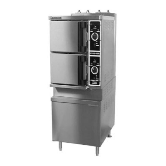
GAS FIRED STEAMER
MODELS:
STHE-7-TGG
STHE-12-TGG
STHE-16-TGG
WARNING
Improper installation, adjustment,
alteration, service or maintenance can
cause property damage, injury or death.
Read the installation, operating and
maintenance instructions thoroughly
before installing or servicing this
equipment.
FOR YOUR SAFETY
Do not store or use gasoline or other
flammable vapours and liquids in the
vicinity of this or any other appliance.
1
2010-09-07
Advertisement

Related Manuals for Market Forge Industries STHE-7-TGG


Summary of Contents for Market Forge Industries STHE-7-TGG
- Page 1 INSTALLATION AND OPERATION MANUAL AND PARTS LIST GAS FIRED STEAMER MODELS: STHE-7-TGG STHE-12-TGG STHE-16-TGG WARNING Improper installation, adjustment, alteration, service or maintenance can cause property damage, injury or death. Read the installation, operating and maintenance instructions thoroughly before installing or servicing this equipment.
- Page 2 INSTALLATION AND OPERATION MANUAL AND PARTS LIST, MODELS: STHE-7-TGG, STHE-12-TGG, STHE-16-TGG IMPORTANT NOTES FOR INSTALLATION AND OPERATION Retain this manual for future reference. NOTICE Instructions to be followed in the event that the operator of this appliance smells gas must be posted in a prominent location. This information shall be obtained by consulting the local gas supplier.
-
Page 3: Table Of Contents
INSTALLATION AND OPERATION MANUAL AND PARTS LIST, MODELS: STHE-7-TGG, STHE-12-TGG, STHE-16-TGG TABLE OF CONTENTS DESCRIPTION PAGE 1.0 SERVICE CONNECTIONS ..........4 2.0 INTRODUCTION . -
Page 4: Service Connections
INSTALLATION AND OPERATION MANUAL AND PARTS LIST, MODELS: STHE-7-TGG, STHE-12-TGG, STHE-16-TGG 1.0 SERVICE CONNECTIONS PART NUMBER 10225R0 2010-09-07... -
Page 5: Introduction
60-minute-long duration cooking. Two gas fired, stainless steel generators operating at “0" psi (0 kPa) and rated at 70,000 BTU (STHE-7-TGG) or 95,000 BTU (STHE-12- TGG and STHE-16-TGG) are located in the bottom cabinet and may be operated separately. - Page 6 INSTALLATION AND OPERATION MANUAL AND PARTS LIST, MODELS: STHE-7-TGG, STHE-12-TGG, STHE-16-TGG INSTALLATION SETTING IN PLACE The location of installation must be under an exhaust hood, which will remove small amounts of water vapor emitted when the cooker doors are opened, and exhaust fumes. Level the unit in final location by turning the adjustable feet.
- Page 7 INSTALLATION AND OPERATION MANUAL AND PARTS LIST, MODELS: STHE-7-TGG, STHE-12-TGG, STHE-16-TGG 2.0 GENERAL Gas installation to conform to local codes, or in absence of local codes, with the National Fuel Gas Code - ANSI Z223.1/NFPA 54. In Canada installation to be in accordance with the Natural Gas and Propane Installation Code, CSA B149.1.
- Page 8 INSTALLATION AND OPERATION MANUAL AND PARTS LIST, MODELS: STHE-7-TGG, STHE-12-TGG, STHE-16-TGG INSTALLATION (Continued) 2.3 CLEARANCES: Adequate clearance must be provided in aisle and at the side and back. Adequate clearances for air openings into the combustion chamber must be provided, as well as for serviceability for use on noncombustible floors.
- Page 9 INSTALLATION AND OPERATION MANUAL AND PARTS LIST, MODELS: STHE-7-TGG, STHE-12-TGG, STHE-16-TGG INSTALLATION (Continued) GAS CONNECTION: The Serial and Rating Plate on the unit indicates the type of gas your unit is equipped to burn. DO NOT connect to any other gas type.
- Page 10 INSTALLATION AND OPERATION MANUAL AND PARTS LIST, MODELS: STHE-7-TGG, STHE-12-TGG, STHE-16-TGG INSTALLATION (Continued) PLUMBING CONNECTIONS: WARNING: Plumbing connections must comply with applicable Sanitary, Safety and Plumbing Codes. Two water lines are provided. Connect water supply lines to the 3/8" copper tubes at the rear of the steamer.
- Page 11 INSTALLATION AND OPERATION MANUAL AND PARTS LIST, MODELS: STHE-7-TGG, STHE-12-TGG, STHE-16-TGG INSTALLATION (Continued) COLD WATER CONDENSER: The steamer is equipped with a cold water condenser, in the rear of the cooking chamber, which helps to condense the steam prior to discharge into the drain. The steamer freely vents itself by the negative pressure created by the condensate water drainage.
-
Page 12: Performance Check
INSTALLATION AND OPERATION MANUAL AND PARTS LIST, MODELS: STHE-7-TGG, STHE-12-TGG, STHE-16-TGG 3.0 PERFORMANCE CHECK WARNING: The steamer and its parts are hot. Use care when operating, cleaning or servicing the steamer. The cooking compartment contains live steam. Stay clear while opening door. -
Page 13: Operation Instructions
INSTALLATION AND OPERATION MANUAL AND PARTS LIST, MODELS: STHE-7-TGG, STHE-12-TGG, STHE-16-TGG 4.0 OPERATION INSTRUCTIONS LIGHTING 1. Ensure power, gas and water supply is on. 2. Turn power switch “ON”. 3. Steam generator tanks will begin filling with water. 4. Once proper water level has been reached, the ignition light will come on and should remain on until the ready light comes on. - Page 14 INSTALLATION AND OPERATION MANUAL AND PARTS LIST, MODELS: STHE-7-TGG, STHE-12-TGG, STHE-16-TGG 4.0 OPERATION INSTRUCTIONS (Continued) PREHEATING Before each initial operation of the cooker, and at any other time when the cooking compartment is cold, a 1-minute preheating period is required. To preheat the cooker, put steam source into operation and proceed as follows: 1.
- Page 15 INSTALLATION AND OPERATION MANUAL AND PARTS LIST, MODELS: STHE-7-TGG, STHE-12-TGG, STHE-16-TGG 4.0 OPERATION INSTRUCTIONS (Continued) SHUT-DOWN PROCEDURE No shut-down procedure is required for the cooker except to check that both timer dials (1) are in the OFF position and that both compartment doors are open. When all cooking has been completed for the day, the steam source must be shut off.
- Page 16 INSTALLATION AND OPERATION MANUAL AND PARTS LIST, MODELS: STHE-7-TGG, STHE-12-TGG, STHE-16-TGG 4.0 OPERATION INSTRUCTIONS (Continued) Drip/Spill Trough Drainage The Pressureless Steam Cookers have a drip/spill trough below the cooking compartment door. It will catch any condensate gathering on the front of the unit when the door is opened.
- Page 17 INSTALLATION AND OPERATION MANUAL AND PARTS LIST, MODELS: STHE-7-TGG, STHE-12-TGG, STHE-16-TGG 4.0 OPERATION INSTRUCTIONS (Continued) NOTE Each cooking compartment has its own steam generator and controls and can be operated independently. TEST KITCHEN BULLETIN Pressureless Cooker - Facts On Parade Frozen vegetables should always be cooked in perforated 12"...
- Page 18 STEAM COOKING The Pressureless Cooker is a two compartment unit. The STHE-7-TGG holds seven 12" x 20" x 2- ½" or four 12" x 20" x 4" pans. The STHE-12-TGG holds twelve 12" x 20" x 2-½” or six 12"...
- Page 19 INSTALLATION AND OPERATION MANUAL AND PARTS LIST, MODELS: STHE-7-TGG, STHE-12-TGG, STHE-16-TGG COOKING GUIDELINES The following guidelines given are suggested quantities, time settings and estimated numbers of orders per pan. COOKING GUIDELINES MISCELLANEOUS APPROX. RECOMMENDED NUMBER WEIGHT PER 12" X 20" (1/1)
- Page 20 INSTALLATION AND OPERATION MANUAL AND PARTS LIST, MODELS: STHE-7-TGG, STHE-12-TGG, STHE-16-TGG FROZEN VEGETABLES Peas (Loose) 7 ½ lbs (3.4 kg) 2 ½" (65 mm) 30 3 oz (85 g) Spinach 9 lbs (4 kg) 2 ½" (65 mm) Must be defrosted...
- Page 21 INSTALLATION AND OPERATION MANUAL AND PARTS LIST, MODELS: STHE-7-TGG, STHE-12-TGG, STHE-16-TGG COOKING GUIDELINES (Continued) VEGETABLES APPROXIMATE RECOMMENDED NUMBER APPROX. 12" X 20" (1/1) TIMER COOKED ITEM FROZEN PERFORATED NUMBER OF SETTINGS IN SERVINGS WEIGHT PER PANS MINUTES PER PAN Beans, Snap Green 6 lbs (2.7 kg)
- Page 22 INSTALLATION AND OPERATION MANUAL AND PARTS LIST, MODELS: STHE-7-TGG, STHE-12-TGG, STHE-16-TGG COOKING GUIDELINES (Continued) VEGETABLES - CANNED APPROXIMATE RECOMMENDED NUMBER WEIGHT PER 12" X 20" (1/1) TIMER COOKED ITEM PERFORATED NUMBER OF SETTINGS IN SERVINGS PANS MINUTES PER PAN Vegetables, 7 lbs (3.2 kg)
-
Page 23: Preventive Maintenance
INSTALLATION AND OPERATION MANUAL AND PARTS LIST, MODELS: STHE-7-TGG, STHE-12-TGG, STHE-16-TGG 5.0 PREVENTIVE MAINTENANCE A good preventive maintenance program begins with the daily cleaning procedure. Additional preventive maintenance operations are presented in this section. In establishments that employ full-time maintenance personnel, the tasks described can be assigned to them. For other installations, tasks requiring mechanical or electrical experience should be performed by an authorized service agency. - Page 24 INSTALLATION AND OPERATION MANUAL AND PARTS LIST, MODELS: STHE-7-TGG, STHE-12-TGG, STHE-16-TGG MONTHLY REMOVAL OF SCALE DEPOSITS It is recommended that your steamer be delimed once a month, or more often if necessary. Should your steamer develop a heavy build-up of lime scale deposits, use the CLR TREATMENT KIT available from your authorized servicer.
-
Page 25: Troubleshooting
INSTALLATION AND OPERATION MANUAL AND PARTS LIST, MODELS: STHE-7-TGG, STHE-12-TGG, STHE-16-TGG 6.0 TROUBLESHOOTING GENERAL The information in this section is intended to assist both the operator and service personnel in locating the general source of problems that may occur with the cooker. Before following any of the procedures given in this section, the operator should be thoroughly familiar with the operating instructions and the function of all controls that are described. - Page 26 INSTALLATION AND OPERATION MANUAL AND PARTS LIST, MODELS: STHE-7-TGG, STHE-12-TGG, STHE-16-TGG 6.0 TROUBLESHOOTING (Continued) ELECTRICAL INSPECTION The first step in any electrical troubleshooting procedure is a thorough physical inspection of all wiring connections. To access electrical components, remove the right-side access panel on the upper cabinet.
- Page 27 INSTALLATION AND OPERATION MANUAL AND PARTS LIST, MODELS: STHE-7-TGG, STHE-12-TGG, STHE-16-TGG GENERAL TROUBLESHOOTING GUIDE PROBLEM PROBABLE CAUSE REMEDY Constant steam position Locate external circuit breaker for incoming OOKING INDICATOR LIGHT FAILS TO power and place in ON position. LIGHT WITH...
- Page 28 INSTALLATION AND OPERATION MANUAL AND PARTS LIST, MODELS: STHE-7-TGG, STHE-12-TGG, STHE-16-TGG ELECTRICAL FAULT ISOLATION GUIDE FAILURE FAULT LOCATION CONSTANT STEAM a. Incoming power ILL NOT OPERATE IN EITHER MINUTE TIMER POSITIONS b. Timer c. Door interlock switch d. Wiring CONSTANT STEAM a.
- Page 29 INSTALLATION AND OPERATION MANUAL AND PARTS LIST, MODELS: STHE-7-TGG, STHE-12-TGG, STHE-16-TGG 60-MINUTE TIMER Timer Contacts Defective timer contacts will result in failure of either cooker compartment to operate. When this occurs, remove the control pan and proceed as follows: 1. Turn off power to the cooker at external circuit breaker.
- Page 30 INSTALLATION AND OPERATION MANUAL AND PARTS LIST, MODELS: STHE-7-TGG, STHE-12-TGG, STHE-16-TGG Door Interlock Switch Malfunction of the cooker door interlock switch prevents timer indicator lights from turning on and steam solenoid from opening when the timer dial is set. If steam does not enter the compartment and the cooking indicator light fails to turn on with the door latch securely engaged, the fault may be in the door interlock switch.
- Page 31 INSTALLATION AND OPERATION MANUAL AND PARTS LIST, MODELS: STHE-7-TGG, STHE-12-TGG, STHE-16-TGG Buzzer If the buzzer does not sound at the termination of the operator-selected timer setting (timer dial returned to “0-Minute” position), the fault may be a defective buzzer. Buzzer operation is verified using an AC volt-meter at buzzer coil connections with input power on and selector switch and coinciding timer dial set at the “0-Minute”...
- Page 32 INSTALLATION AND OPERATION MANUAL AND PARTS LIST, MODELS: STHE-7-TGG, STHE-12-TGG, STHE-16-TGG 6.0 TROUBLESHOOTING (Continued) ADJUSTMENTS All units are adjusted at the factory. In case of operation problems at initial installation, check type of gas supply and manifold pressure and compare it with information on the rating plate.
-
Page 33: Maintenance
INSTALLATION AND OPERATION MANUAL AND PARTS LIST, MODELS: STHE-7-TGG, STHE-12-TGG, STHE-16-TGG 7.0 MAINTENANCE Door Gasket Replacement The cooking compartment door gaskets are made of a silicone-type rubber material that is very durable but subject to wear during normal operation. Should the gasket leak, readjust the door gasket to the unit or replace it. -
Page 34: Parts List
INSTALLATION AND OPERATION MANUAL AND PARTS LIST, MODELS: STHE-7-TGG, STHE-12-TGG, STHE-16-TGG 8.0 PARTS LIST FIGURE 1 PART NUMBER 10225R0 2010-09-07... - Page 35 INSTALLATION AND OPERATION MANUAL AND PARTS LIST, MODELS: STHE-7-TGG, STHE-12-TGG, STHE-16-TGG FIGURE 1 ITEM PART NO. DESCRIPTION QUANTITY STHE- STHE- STHE- 7-TGG 12-TGG 16-TGG 7159-4 Left Hand Side Panel 7159-1 Left Hand Side Panel 7159-2 Left Hand Side Panel 8-5076-8...
- Page 36 INSTALLATION AND OPERATION MANUAL AND PARTS LIST, MODELS: STHE-7-TGG, STHE-12-TGG, STHE-16-TGG ITEM PART NO. DESCRIPTION QUANTITY STHE- STHE- STHE- 7-TGG 12-TGG 16-TGG 08-3826 Dial 60 Hz (60 Minutes) 08-6464 Timer (60 Minutes) 9124-2 Switch, 120V 9109-1 Rotary Shaft Seal 5288-1...
- Page 37 INSTALLATION AND OPERATION MANUAL AND PARTS LIST, MODELS: STHE-7-TGG, STHE-12-TGG, STHE-16-TGG ITEM PART NO. DESCRIPTION QUANTITY STHE- STHE- STHE- 7-TGG 12-TGG 16-TGG 7625-1 Pan Rack 2681-2 Pan Rack 2667-1 Centre Pan Support 9026-18 Gas Flex Tube, 1/2" x 18" 9026-24 Gas Flex Tube, 1/2"...
- Page 38 INSTALLATION AND OPERATION MANUAL AND PARTS LIST, MODELS: STHE-7-TGG, STHE-12-TGG, STHE-16-TGG ITEM PART NO. DESCRIPTION QUANTITY STHE- STHE- STHE- 7-TGG 12-TGG 16-TGG 3-686D Connector, 3/8" C x 1/2" MPT 5162-1 Generator Fill Solenoid, Upper Cavity 5162-1 Generator Fill Solenoid, Lower Cavity 3-686A Connector, 3/8"...
- Page 39 INSTALLATION AND OPERATION MANUAL AND PARTS LIST, MODELS: STHE-7-TGG, STHE-12-TGG, STHE-16-TGG ITEM PART NO. DESCRIPTION QUANTITY STHE- STHE- STHE- 7-TGG 12-TGG 16-TGG 9083-30 Bottom Right, Flex Steam Tube, 30" 9083-48 Top Left Flex Steam Tube, 48" 9083-36 Flex Steam Tube, 36"...
- Page 40 INSTALLATION AND OPERATION MANUAL AND PARTS LIST, MODELS: STHE-7-TGG, STHE-12-TGG, STHE-16-TGG ITEM PART NO. DESCRIPTION QUANTITY STHE- STHE- STHE- 7-TGG 12-TGG 16-TGG 3-686D Connector 3-6812E Connector - Drain, 3/4C” x 3/4" MPT 3-U6BE Union Elbow, 3/4" - Drain 5784-1 Relief Valve Extension...
- Page 41 INSTALLATION AND OPERATION MANUAL AND PARTS LIST, MODELS: STHE-7-TGG, STHE-12-TGG, STHE-16-TGG FIGURE 2 PART NUMBER 10225R0 2010-09-07...
- Page 42 INSTALLATION AND OPERATION MANUAL AND PARTS LIST, MODELS: STHE-7-TGG, STHE-12-TGG, STHE-16-TGG FIGURE 2 ITEM PART NO. DESCRIPTION QUANTITY STHE- STHE- STHE- 7-TGG 12-TGG 16-TGG 8-5060-7 Door Frame, Bottom 8-5060-8 Door Frame, (2840) 8-5060-9 Door Frame, Top 3103-1 Door Frame 3903-2...
- Page 43 INSTALLATION AND OPERATION MANUAL AND PARTS LIST, MODELS: STHE-7-TGG, STHE-12-TGG, STHE-16-TGG ITEM PART NO. DESCRIPTION QUANTITY STHE- STHE- STHE- 7-TGG 12-TGG 16-TGG 8-5065-8 Door Panel 8-5065-9 Door Panel, Top 8-5065-6 Door Panel 9-1011-1 Screw, 10 - 32 x 1/2" 1-34S4 Screw, 10 - 32 x 1/2"...
- Page 44 INSTALLATION AND OPERATION MANUAL AND PARTS LIST, MODELS: STHE-7-TGG, STHE-12-TGG, STHE-16-TGG BURNER PARTS FIGURE 3 PART NUMBER 10225R0 2010-09-07...
- Page 45 INSTALLATION AND OPERATION MANUAL AND PARTS LIST, MODELS: STHE-7-TGG, STHE-12-TGG, STHE-16-TGG FIGURE 3 BURNER PARTS QUANTITY STHE- STHE-12- STHE- ITEM PART NO. DESCRIPTION 7-TGG 16-TGG 7283-1 Burner Bracket Assembly 5861-1 Bracket, Pilot Assembly 5171-024 Pilot Burner, Natural Gas 5171-016 Pilot Burner, Propane Gas...
- Page 46 INSTALLATION AND OPERATION MANUAL AND PARTS LIST, MODELS: STHE-7-TGG, STHE-12-TGG, STHE-16-TGG FIGURE 4 PART NUMBER 10225R0 2010-09-07...
- Page 47 INSTALLATION AND OPERATION MANUAL AND PARTS LIST, MODELS: STHE-7-TGG, STHE-12-TGG, STHE-16-TGG FIGURE 4 ITEM PART NO. DESCRIPTION QUANTITY STHE- STHE- STHE- 7-TGG 12-TGG 16-TGG 3821-1 Buzzer, 120V 7926-1 Component Mounting Board 9126-1 Operating Thermostat 9210-2 Ignition Module, Intermittent Pilot 9123-1...
Need help?
Do you have a question about the STHE-7-TGG and is the answer not in the manual?
Questions and answers