Table of Contents
Advertisement
Quick Links
MODELS:
INSTALLATION
OPERATION
MAINTENANCE
STEAM COOKING
GUIDELINES
PARTS LISTS
PARTS & SERVICE
35 Garvey Street, Everett, MA 02149:
Tel: (617) 387-4100
Fax: (617) 387-4458
custserv@mfii.com,
www.mfii.com
OWNER'S MANUAL
CAPELLA STEAMER
CAPELLA - 4
CAPELLA - 6
1/2012
CAPELLA - 8
CAPELLA - 10
CAPELLA - 12
Advertisement
Table of Contents

Subscribe to Our Youtube Channel
Related Manuals for Market Forge Industries CAPELLA - 4


Summary of Contents for Market Forge Industries CAPELLA - 4
- Page 1 OWNER’S MANUAL CAPELLA STEAMER MODELS: CAPELLA - 4 CAPELLA - 8 CAPELLA - 6 CAPELLA - 10 CAPELLA - 12 INSTALLATION OPERATION MAINTENANCE STEAM COOKING GUIDELINES PARTS LISTS PARTS & SERVICE...
-
Page 2: Table Of Contents
TABLE OF CONTENTS IMPORTANT NOTES FOR SAFETY, INSTALLATION AND OPERATION ..........4 A. INTRODUCTION ..........................5 1) Product Description ......................5 2) Safety Features ......................... 5 3) Dimensions ........................5 4) Service Contacts ........................ 6 B. SERVICE CONNECTIONS ........................ 7 C. -
Page 3: Important Notes For Safety, Installation And Operation
IMPORTANT NOTES FOR SAFETY, INSTALLATION AND OPERATION WARNING: This is the safety alert symbol. It is used to alert you to potential personal injury hazards. Obey all safety messages that follow this symbol to avoid possible injury or death. WARNING: Improper installation adjustment, alteration, service or maintenance can cause property damage, injury or death. -
Page 4: Introduction
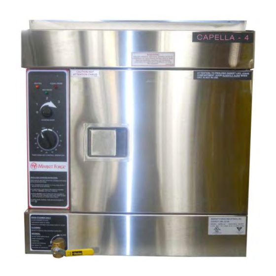
INTRODUCTION 1) Product Description: Congratulations on purchasing the Market Forge Capella. The Capella is a single compartment countertop or two-compartment floor model steamer featuring pressureless steam cooking and a circulating fan inside the cooking chamber to speed cooking. The cooking chamber of the Capella is treated with a scratch resistant, non-stick surface. -
Page 5: Service Contacts
Should repairs be required, a network of authorized agencies is available to assist with prompt service. A current Directory of Authorized Service Agencies may be obtained by contacting: Market Forge Industries, Inc. 35 Garvey Street Everett, Massachusetts 02149-4403 Telephone: (617) 387-4100... -
Page 6: Service Connections
SERVICE CONNECTIONS Models: Capella – 4 & Capella – 6 Capella Service Connections: ELECTRICAL (Capella - 4) 60 Hz Electrical Connection – 1 1/8” knock-out hole Voltage Amps for electrical connection. Rating provided on data label. Drain – A 6 ft. removable drain hose... - Page 7 SERVICE CONNECTIONS (continued) Models: Capella – 8, Capella – 10 & Capella – 12 Capella Service Connections: ELECTRICAL (Capella - 4) 60 Hz Electrical Connection – 1 1/8” knock-out hole Voltage Amps for electrical connection. Rating provided on data label.
-
Page 8: Installation
INSTALLATION 1) Damage Inspection: Reporting shipping damage is the responsibility of the purchaser. Do not discard packaging if filing a freight damage claim. Upon receipt of steamer immediately inspect the exterior of packaging for damage. Remove wrapping. Inspect the exterior of the Capella for visible shipping damage. 2) Unpacking / removal from pallet: To remove the steamer from the pallet, carefully cut the strapping. -
Page 9: Startup Procedure
hole, fits over the pre-installed rack screws at the top of the cooking chamber wall. The curved wires on the rack should be facing to the front of the steamer. Repeat this process for the rack mounted on the other side. These racks are designed to be removed easily for cleaning. - Page 10 water level sensing probe still needs to be cleaned, both lights will remain on until the probe is cleaned. CAUTION: Do not add water to a hot, dry cooking chamber. Damage to the cooking chamber may result. If the cooking chamber has run dry, let it cool before refilling. 4) Clean probe light: If the CLEAN PROBE light (red) is illuminated, the water level sensing probe is unable to sense water.
-
Page 11: Cleaning Guidelines
WARNING: The reservoir water may still be hot. It is advisable to let the water cool down prior to draining. NOTE: Opening the steamer door will speed the cooling process. It is also advisable to leave the steamer door open when not in use. This will lengthen the life of the door gasket. CLEANING GUIDELINES 1) Daily Cleaning Once the power is off and the reservoir has been drained, a simple cleaning process should be... - Page 12 If the unit is heavily scaled, it may be necessary to repeat the process. To reorder Stellar Descaling Powder, Part Number 92-1009 (case of four 2 lb. bottles), contact your local Parts and Service agency or: Market Forge Industries, Inc. 35 Garvey Street Everett, Massachusetts 02149-4403...
-
Page 13: Steam Cooking Guidelines
G STEAM COOKING GUIDELINES 1) Cooking with atmospheric / pressureless steam: Atmospheric or pressureless steaming is perfect for a la carte cooking. The door can always be opened during cooking to add or remove pans of food, to season food or to check on its progress. -
Page 14: Other Helpful Hints
c) Use solid pans where appropriate: scrambled eggs, rice, beans, dehydrated foods, prepared casseroles, sauces, cake or other desserts (you can bake a cake in atmospheric steam), and when you want to prevent food from dripping on a lower pan. d) When cooking proteins (meat, poultry or seafood) use a solid catch pan under the perforated pan. -
Page 15: Cautions
The cooking chamber is designed to retain heat. It may still be hot to the touch when cleaning. Wear protective gloves, or wait for the surface to cool before cleaning. Do not add cold water to a hot empty cooking chamber until unit has cooled down or damage may result. -
Page 16: Wiring Diagrams
WIRING DIAGRAM 1) 208/240 Volts Figure 1... -
Page 17: 480 Volts
2) 480 Volts Figure 2... -
Page 18: Illustrated Parts List
ILLUSTRATED PARTS LIST 1) Cabinet Assembly Figure 3 Full Front View Figure 4 Control Panel ITEM PART DESCRIPTION 92-0727 Panel, Left Side (4 Pan) 92-0729 Panel, Left Side (6 Pan) - Not Shown 92-0726 Panel, Right Side (4 Pan) - Not Shown 92-0728 Panel, Right Side (6 Pan) - Not Shown 92-0008... -
Page 19: Figure 5
Cabinet Assembly continued Figure 5 Oven Cavity (with Wire Racks) Figure 6 Oven Cavity (no Wire Racks) ITEM PART DESCRIPTION Wire Rack, Left and Right (4 Pan unit) 92-0116 92-0160 Wire Rack, Left and Right (6 Pan unit) 92-0404 Oven Cavity Bolster (Extender), Stainless Steel (6 Pan unit only) 92-0054 Water Level Probe 92-0078... -
Page 20: Door Assembly
2) Door Assembly Figure 7 Figure 8 Inside View of Door Outside View of Door ITEM PART DESCRIPTION 92-0548 Door Assembly (4 Pan) 92-0549 Door Assembly (6 Pan) 92-0063 Door Gasket (4 Pan) 92-0159 Door Gasket (6 Pan) 92-0380 Gasket Plate (4 Pan) 92-0381 Gasket Plate (6 Pan) 92-0064... -
Page 21: General Assembly
3) General Assembly Figure 9 Oven Rear View ITEM PART DESCRIPTION 08-5433 Copper Tubing, ½” Dia. x, 6” Length 10-2793 Elbow ½”, 90° , IPS, Brass 92-0225 Bushing, ¾” x ½” NPT Hex Stainless Steel (not Shown) 92-0021 Elbow, 90° , 5/8” Compression x ½” MNPT, Brass 92-0008 Panel, Rear (4 Pan) 92-0357... -
Page 22: Figure 10
General Assembly (continued) Figure 10 Figure 11 Inside Drain Line Inside Drain Line Exit ITEM PART DESCRIPTION 92-0227 Elbow, ¾” Street, Stainless Steel 08-4852 Hose Barb Adapter, ¾” 92-0088 Clamp, Hose 92-0090 Tubing, Silicone, 1” OD 92-0220 Hose Barb Adapter, ½” X ¾” 10-2793 Elbow, Brass, ½”... -
Page 23: Control Panel Components
4) Control Panel Components & Heating Elements Figure 12 View looking up from behind Control Panel See Figure 14 For Details See Figure 15 For Details Figure 13 Left Side, Full view, Open ITEM PART DESCRIPTION 92-0069 Terminal Block 08-6308 Reed (Proximity) Switch, (Door Safety Switch) -
Page 24: Figure 14
Control Panel Components & Heating Elements (continued) Figure 14 Slide Out Component Panel (Upper) ITEM PART DESCRIPTION 92-0183 Controller, Temperature, 240V 92-0189 Relay, 220V, DPDT 92-0230 Controller, Waterfill, 208V/240V 92-0186 Buzzer, 240V 92-0140 Terminal Strip, 6 Pole 92-0414 Fuse, 2 Amp 08-6469 Fuse Block (Holder) 92-0228... -
Page 25: Figure 15
Control Panel Components & Heating Elements (continued) Figure 15 Stationary Component Panel (Lower) and Heating Elements Figure 16 Upper Inside of Cavity View (with no Fan Baffle (Shield)) ITEM PART DESCRIPTION 10-5943 Contactor, 240V 92-0140 Terminal Strip, 6 Pole 4 (4 Pan unit) 92-0199 Heater Element, Alum (for all 208V units) 5 (6 Pan unit) -
Page 26: Figure 17
Control Panel Components & Heating Elements (continued) Figure 17 Slide Out Control Panel ITEM PART DESCRIPTION 92-0185 Light, Red, 250V 92-0184 Light, Amber, 250V 92-0231 Light, Green, 250V 92-0125 Rotary Switch, 4 Position 92-0137 Timer, 240V, 60 Minutes... -
Page 27: Convection Fan And Motor Components
5) Convection Fan and Motor Components Figure 18 Fan Motor and Pulley Assembly Figure 19 Convection Fan ITEM PART DESCRIPTION 08-6905 Fan Motor (230V) 08-5601 Pulley, .25” Dia. Bore, (22 Teeth) 08-5600 Pulley, .25” Dia. Bore, (18 Teeth) 92-0606 Mounting Pedestal 92-0605 Mounting Plate 92-0676...
Need help?
Do you have a question about the CAPELLA - 4 and is the answer not in the manual?
Questions and answers