
Subscribe to Our Youtube Channel
Related Manuals for Omega CL3001


Summary of Contents for Omega CL3001
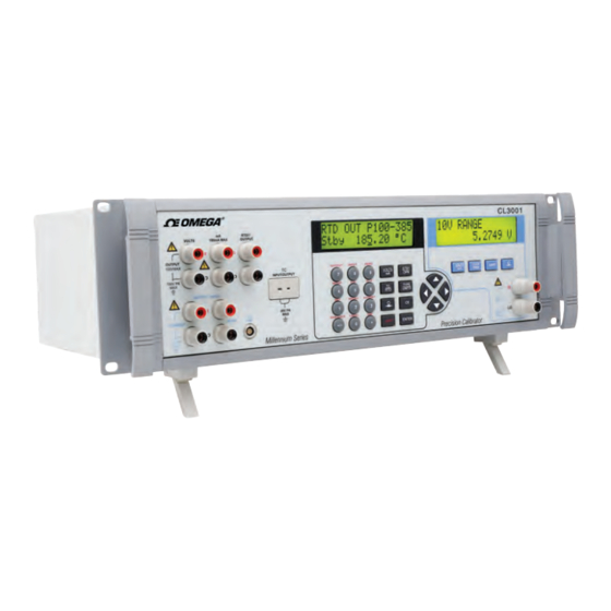
- Page 1 User’s Guide Shop online at omega.com e-mail: info@omega.com For latest product manuals: www.omegamanual.info NORWALK, CT CL3001 Lab Calibrator...
- Page 2 Fax: (203) 359-7700 e-mail: info@omega.com For Other Locations Visit omega.com/worldwide The information contained in this document is believed to be correct, but OMEGA accepts no liability for any errors it contains, and reserves the right to alter specifications without notice.
-
Page 3: Table Of Contents
3001 Operator’s Manual 1. Introduction ..........1 1.1 Customer Service . - Page 4 8. LCD and Remote Interface Setup Procedures ....41 9. Remote Interface ........41 9.1 Introduction .
-
Page 5: Introduction
1. Introduction The OMEGA CL3001 calibrator is an accurate full-featured temperature, pressure and DC calibrator intended for R & D, manufacturing and calibration lab applications. The unit's simple design and ease of operation allow users to quickly familiarize themselves with its operations and features. Time saving functions... -
Page 6: Safety Information
Remove the Packing List and verify that all of the listed equipment has been received. If there are any questions about the shipment, please call OMEGA at 800-872-9436. Check to see if your basic calibrator package is complete. It should include: •... - Page 7 Read the User’s Manual (Important Information) The following definitions apply to the terms "Warning" and "Caution". • " Warning" identifies conditions and actions that may pose hazards to the user. • " Caution" identifies conditions and actions that may damage the instrument being used.
-
Page 8: Calibrator Description
Refer to the pressure module documentation for material compatibility. Make sure to remove all test connections before powering up the CL3001. Failure to do so could lead to damage of the CL3001 or the unit under test. 2. Calibrator Description 2.1 Front Panel Overview... -
Page 9: Primary Input/Output Terminals
Figure 1 - Front Panel Item Name Description Primary input/output terminals See section 2.2 for details Primary input/output display and controls See section 2.3 for details Isolated input display, controls, and terminals See section 2.4 for details 2.2 Primary Input/Output Terminals Figure 2 describes the primary input/output terminals in detail. -
Page 10: Primary Input/Output Display And Controls
Item Name Description VOLTS DC voltage output terminals. See notes 1 and 2 below. DC current output terminals. See notes 1 and 2 below. RTD/O OUTPUT Two wire RTD and Ohms output terminals. See notes 1 and 2 below. TC INPUT/OUTPUT Thermocouple input and output terminals. - Page 11 Item Name Description Display A 2 line, 16 character, display providing all visual user feedback for the primary output and input operations.See section 2.6 for layout details, and section 2.7 for possible error messages. Numeric and secondary Output value data entry keys. function keys Secondary function selection per the text printed above the...
- Page 12 Select Auto-range or Range Lock for voltage output. LOCAL Press to regain local control of the CL3001 after the remote command REMOTE has been received; in this case all keys except this one are ignored. When the remote command LOCKOUT has been...
- Page 13 For all output modes, except Thermocouple, toggle between Standby and Operate modes.In Standby mode, any change to the output value in the display is not driven to the terminals until the Operate mode is selected.In Operate mode, each change to the output value in the display is driven to the terminals immediately, except for DC voltages greater then 30V...
-
Page 14: Isolated Input Display, Controls, And Terminals
2.4 Isolated Input Display, Controls, and Terminals Figure 4 describes the isolated input display, controls, and terminals in detail. Figure 4 - Isolated Input Display, Controls, and Terminals Item Name Description Display A 2 line, 16 character, display providing all visual user feedback for the isolated input operations. -
Page 15: Rear Panel
resistor.Note that activating this resistor drops the maximum load driving capability from 1000 ohms at 20mA to 750 ohms at 20mA. Select Pressure input mode. Subsequent presses of this key cycle through the pressure units.Pressure input mode uses the pressure module connector on the primary input/output side. -
Page 16: Display Layouts
Item Description RS-232 9 pin connector for remote control of the CL3001 via any computer's serial interface. GPIB IEEE 488.2 connector for remote control of the CL3001 via a GPIB bus. Service port for updating the CL3001 firmware. Chassis ground terminal internally connected to the ground prong of the AC power inlet. - Page 17 Blank for RTD inputs Cold junction selection for thermocouple inputs and outputs: XCJC External cold junction compensation; the CL3001 automatic cold junction compensation is turned off, i.e. 0 mV is always 0°C Blank Internal cold junction compensation; the CL3001...
- Page 18 Input or output value Units c) Primary and Isolated Pressure Display Figure 8 - Primary and Isolated Pressure Display Layout Item Description UnitsOn the primary display, rem appears to the left during remote operation Input value d) Isolated Voltage and Current Display Figure 9 - Isolated Voltage and Current Display Layout Item Description...
-
Page 19: Error Messages
OVER LOAD For DC voltage output mode, the current required to generate the output exceeds the CL3001 specifica- tions.For DC current mode, the resistance of the circuit exceeds the CL3001 specifications. For input modes, the measured value exceeds the upper limit of the selected input mode range.For output... -
Page 20: Getting Started
If the problem persists, report the problem to Omega immediately. Warm up time is twice the time since last warmed up, to a maximum of 30 minutes. For good stability it is best to leave the CL3001 on all the time. 4. Primary Inputs and Outputs 4.1 DC Voltage Output... - Page 21 When DC voltage mode is first selected, the CL3001 is placed in the standby (Stby) mode which puts the positive (+) output jack into a high impedance state (>100k ohm) for safety.
-
Page 22: Dc Current Output
When DC current mode is first selected, the CL3001 is placed in the standby (Stby) mode which puts the positive (+) output jack into a high impedance state (>100k ohm) for safety. -
Page 23: Resistance Temperature Detector (Rtd) And Ohms Measure
• No connection made to the output terminals. • The voltage compliance for a given output current is exceeded. The CL3001 has a typical voltage compliance of 10V so that 4- 20mA application loads of up to 500 ohms can be driven. At maximum current of 100mA, the maximum load is 100 ohms. -
Page 24: Resistance Temperature Detector (Rtd) And Ohms Source
°F and °C. g) For best accuracy, it is advisable to zero the RTD resistance circuit(s) daily, or if the CL3001 is being used outside of the ambient temperature range of 18 to 28 °C. The maximum offset from unit calibration that can be zeroed out is ±0.1 ohm for the high range and ±0.01 ohm for the low range. - Page 25 When RTD/Ω mode is first selected, the CL3001 is placed in the standby (Stby) mode which puts the positive (+) output jack into a high impedance state (>100k ohm) for safety.
-
Page 26: Resistance Temperature Detector (Rtd) With Custom Coefficients
4.5 Resistance Temperature Detector (RTD) with Custom Coefficients The CL3001 has the capability to store coefficients for up to 5 custom RTD curves. To enter the coefficients for a custom RTD curve: Select RTD measure or source mode as described in the preceding sections. - Page 27 To use a different custom RTD curve, press the twice to display the USR_DEF selection prompt. The USR_DEF function of the CL3001 uses the Calendar-Van Dusen equation for sourcing and measuring custom RTD's. The C coefficient is only used for the subrange -260 to 0 degrees Celsius.
-
Page 28: Standard Platinum Resistance Thermometer (Sprt) Coefficients
4.6 Standard Platinum Resistance Thermometer (SPRT) Coefficients The SPRT function of the CL3001 uses ITS-90 standard coefficients as a basis for measuring a SPRT. The five custom coefficients are entered as deviations from the standard coefficients, and as such, all of them are set to zero at the factory. -
Page 29: Thermocouple (T/C) Measure
SPRT selection prompt. 4.7 Thermocouple (T/C) Measure The CL3001 can measure all common thermocouple types in °F or °C, plus basic millivolts from -10.0 to 75.0 mV. The following common thermocouple types are supported: B, C, E, J, K, L, N, R, S, T, U, XK, BP a) Disconnect any test leads from external devices. -
Page 30: Thermocouple (Tc) Source
For best accuracy, it is advisable to zero the T/C millivolt circuit daily, or if the CL3001 is being used outside of the ambient temperature range of 18 to 28 °C. The maximum offset from unit calibration that can be zeroed out is ±1 mV. - Page 31 Connect the unit under test to the thermocouple terminals of the CL3001 using a standard T/C miniplug as shown in figure 15. One pin is wider than the other; do not attempt to force the plug in the wrong polarization.
-
Page 32: Pressure Measure
For best accuracy, it is advisable to zero the T/C millivolt circuit daily, or if the CL3001 is being used outside of the ambient temperature range of 18 to 28 °C. This procedure is described in section 4.7 on thermocouple measurements. -
Page 33: Isolated Inputs
5. Isolated Inputs 5.1 Voltage Input The CL3001 can measure DC voltages from 0 V to 100 V, using the following two ranges for maximum accuracy: 10 V, and 100 V. a) Disconnect any test leads from external devices. -
Page 34: Current Input
5.2 Current Input The CL3001 can measure DC current from 0 mA to 50 mA. a) Disconnect any test leads from external devices. b) Press the key to select isolated DC voltage and current input mode, if not already selected. If the DC current mode is not displayed, press the key again to cycle to it. -
Page 35: Output Setpoints
Connect the pressure module to the CL3001 as shown in figure Figure 19 - Isolated Pressure Module Connection b) Press the key. The CL3001 automatically senses which pressure module is attached and sets its range accordingly. c) If necessary, press the key again to cycle through the pressure units until the desired one is displayed. - Page 36 To set a setpoint: Select the output mode. Enter the output value for the setpoint. Press the keys to select the SET function. At the setpoint number selection prompt "SET POINT#", press the numeric key, 1 to 9, corresponding to the setpoint to be set.
-
Page 37: Application Notes
7. Application Notes 7.1 P/I Transmitter Figure 20 - P/I Transmitter Application 1. Disconnect any test leads from external devices. 2. Select pressure input on the primary display as described in section 4.9. 3. Select current input on the isolated display as described in section 5.2. -
Page 38: I/P Transmitter
7.2 I/P Transmitter Figure 21 - I/P Transmitter Application 1. Disconnect any test leads from external devices. 2. Select current output on the primary display as described in section 4.2. 3. Select pressure input on the isolated display as described in section 5.3 4. -
Page 39: Rtd Test
1. Disconnect any test leads from external devices. 2. Select voltage output on the primary display as described in section 4.1 3. Select current input on the isolated display as described in section 5.2. Select the isolated loop power option. 4. -
Page 40: Rtd Transmitter
RTD Transmitter Figure 24 - RTD Transmitter Application 1. Disconnect any test leads from external devices. 2. Select RTD output on the primary display as described in section 4.4. Select the RTD type which corresponds to the transmitter being tested. 3. -
Page 41: Thermocouple Transmitter
1. Disconnect any test leads from external devices. 2. Select thermocouple input on the primary display as described in section 4.7. Select the thermocouple type which corresponds to the thermocouple being tested. 3. Connect the thermocouple as shown in figure 25. 4. -
Page 42: Rtd Indicator
RTD Indicator Figure 27 - RTD Indicator Application 1. Disconnect any test leads from external devices. 2. Select RTD output on the primary display as described in section 4.4. Select the RTD type which corresponds to the indicator being tested. 3. -
Page 43: I/I Isolator/Transmitter
3. Select voltage input on the isolated display as described in section 5.1. 4. Connect the trip as shown in figure 28. 5. Test and calibrate the trip per the manufacturer's instructions. 7.10 I/I Isolator/Transmitter Figure 29 - I/I Isolator/Transmitter Application 1. -
Page 44: Precision Temperature Measurement With Ibp-2 Probe
7.11 Precision Temperature Measurement with 4-Wire RTD Probe Figure 30 - Precision Temperature Measurement with 4-Wire RTD Probe 1. With the RTD probe and the corresponding custom coefficients, the total system error is 0.03°C. 2. Disconnect any test leads from external devices. 3. -
Page 45: Lcd And Remote Interface Setup Procedures
CL3001. Compatible software for IEEE-488 operation may be purchased from third parties. The RS-232 connection allows one CL3001 to be connected to one PC. The communications speed is slower than IEEE-488, but no extra equipment is required other than a low cost null modem cable. -
Page 46: Setting Up The Rs-232 Port For Remote Control
A typical RS-232 connection is shown in Figure 31. Note the use of a null modem cable for the connection. See section 2.5 for the location of the RS-232 port on the rear panel of the CL3001. 9.2.1 Using the CL3001 on Computers with USB Ports The CL3001 can be used with a computer having only USB ports with the use of a USB to serial converter. -
Page 47: Setting Up The Ieee-488 Port For Remote Control
Figure 31 - RS-232 Remote Connection 9.3 Setting up the IEEE-488 Port for Remote Control The CL3001 is fully programmable for use on a standard IEEE-488 interface bus. The IEEE-488 interface is also designed in compliance with supplemental standard IEEE-488.2, which describes additional IEEE-488 features. -
Page 48: Changing Between Local And Remote Operation
9.4 Changing Between Local and Remote Operation In addition to local mode (front panel operation) and remote, the CL3001 can be placed into a local lockout condition at any time by command of the controller. Combined, the local, remote, and lockout conditions yield four possible operating states as follows. -
Page 49: Ieee-488 Interface Overview
To return the CL3001 to the local with lockout state, send the RS-232 LOCAL command or the IEEE-488 GTL (Go To Local) message. Table 4 summarizes the possible operating state transitions. For more information on IEEE-488 GPIB messages, see section 9.5. -
Page 50: Using Commands
Refer to section 10 for more detailed information about the commands referenced in this section. All commands, units, and text data may be entered in UPPER or lower case letters. The CL3001 converts all lower case letters to upper case before processing. 9.6.1 Types of Commands The commands for the CL3001 can be grouped into the following categories based on how they function. - Page 51 OUT 1 V OPER These could be combined into the compound command: OUT 1 V; OPER These commands instruct the CL3001 to source 1 V DC, and then go into operate mode. Overlapped Commands Commands that begin execution but require slightly more time than the normal communication command/response interval to complete are called overlapped commands.
- Page 52 IEEE Standards. For example, the command REMOTE could be sent as data over the IEEE- 488 interface to place the CL3001 into remote operating mode, but it is not because the IEEE Standards call for the remote function to be sent to the device as the uniline message REN.
-
Page 53: Command Syntax
9.6.2 Command Syntax The following syntax rules apply to all of the remote commands. Information about the syntax of response messages is also given. Parameter Syntax Rules Table 7 lists the units accepted in command parameters and used in responses. All commands and units may be entered in upper or lower case. - Page 54 RS-232 Mode, program:Comm1.Output = "OUT 1 V" + Chr(10) IEEE-488 Mode: OUT 1 V IEEE-488 interface: The CL3001 sends the ASCII character Carriage Return with the EOI control line held high as the terminator for response messages. The CL3001 recognizes the following as terminators when encountered in incoming data: •...
-
Page 55: Checking 3001 Status
CL3001 which indicate various conditions in the instrument. Some registers and queues are defined by the IEEE-488.2 standard, while the rest are specific to the CL3001. In addition to the status registers, the Service Request (SRQ) control line and a 16-element... - Page 56 Figure 33 - Status Register Overview Table 9 lists the status registers and gives the read/write commands and associated mask registers used to access them. Table 9 - Status Register Summary Status Register Read Command Write Command Serial Poll Status Byte (STB) *STB? —...
- Page 57 SRE. When RQS is 1, the CL3001 asserts the SRQ control line on the IEEE-488 interface. You can do a serial poll to read this bit to see if the CL3001 is the source of an SRQ. Master summary status. Set to 1 whenever bits ESB, MAV, EAV, or ISCB are 1 and enabled (1) in the SRE.
- Page 58 1 until the controller reads the ESR, does a device clear, a selected device clear, or sends the reset or *CLS command to the CL3001. The ESE is cleared (set to 0) when the power is turned on. 7) Bit Assignments for the ESR and ESE The bits in the Event Status Register (ESR) and Event Status Enable register (ESE) are assigned as shown in Figure 35.
- Page 59 250 characters. The controller reads it with a statement such as a BASIC INPUT statement, removing what it reads from the queue. If the queue is empty, the CL3001 does not respond to the INPUT statement from the controller. The...
- Page 60 CL3001 can process them, the input buffer fills to capacity. When the input buffer is full, the CL3001 holds off the IEEE-488 bus with the NRFD (Not Ready For Data) handshake line. When the CL3001 has processed a data byte from the full input buffer, it then completes the handshake, allowing the controller to send another data byte.
-
Page 61: Remote Commands
10. Remote Commands 10.1 Introduction Remote commands duplicate actions that can be initiated from the front panel in local operating mode. Following the summary table is a complete alphabetical listing of all commands complete with protocol details. Separate headings in the alphabetical listing provide the parameters and responses, plus an example for each command. - Page 62 *TST? Runs a series of self-tests and returns a "0" for pass or a "1" for fail. If any faults are detected, they are logged into the fault queue where they can be read by the FAULT? query. *WAI Prevents further remote commands from being executed until all previous remote commands have been completed.
-
Page 63: Measurement Commands
Output Commands Command Description OPER Activates the CL3001 output if it is in standby mode. OPER? Returns the operate/standby mode setting. Sets the output of the CL3001. OUT? Returns the present output value of the CL3001. RANGE? Returns the present output range, for voltage and current only. -
Page 64: Error Code Listing
Status Commands Command Description FAULT? Returns the most recent error code in the CL3001 error queue, and then removes that error code from the queue. 10.3 Error Code Listing Error Number Message Class Description Error queue overflow. OPER or STBY was received when the CL3001 is in measure mode or thermocouple source mode. - Page 65 The serial output buffer overflowed. The output overloaded. See display error message OVER LOAD in section 2.7. The CL3001 is out of tolerance. This error is set after a failed initialization or a failed *TST? command. The CL3001 ADC has failed. This error is set after a failed initialization or a failed *TST? command.
-
Page 66: Remote Command Listing
10.4 Remote Command Listing The following is an alphabetical list of all CL3001 remote commands and queries, including the common commands and the device- dependent commands. Each command title includes a checkbox that indicates the remote interface applicability, IEEE-488 and/or RS- 232, and the command group, Sequential or Overlapped;... - Page 67 ESE byte, 0 to 255 Example: *ESE? This example returns decimal 133 (binary 10000101) which indicates that bits 7 (PON), 2 (QYE), 1 (OPC) are enabled. *ESR? IEEE-488 RS-232 Sequential Overlapped Event Status Register query. This command returns the contents of the Event Status Register (ESR) and clears the register.
- Page 68 FUNC? IEEE-488 RS-232 Sequential Overlapped This command returns the present output, measurement, or calibration function for the primary and isolated displays. Parameter: <None> Response: <isolated>,<primary> where <isolated> is one of the following: DC10V measure DC voltage, 10V range DC100V measure DC voltage, 100V range measure DC current PRESSURE...
- Page 69 1. Manufacturer 2. Model number 3. Serial number (always 0) 4. Firmware revision level Example: *IDN? OMEGA, CL3001,0,1.2 This example indicates the manufacturer is Omega, the model is CL3001, the serial number is 0, and the firmware version is 1.2.
- Page 70 ISO_MEAS IEEE-488 RS-232 Sequential Overlapped This command sets the isolated measurement type. Parameter: <value> where <value> is one of the following: DC10V measure DC voltage, 10V range DC100V measure DC voltage, 100V range measure DC current PRESSURE measure pressure Response: <None>...
- Page 71 Example: ISO_PRES_UNIT BAR This example sets the isolated pressure unit to bars. ISO_PRES_UNIT? IEEE-488 RS-232 Sequential Overlapped This command returns the isolated pressure unit. Parameter: <None> Response: <value> where <value> is one of the following: pounds per square inch INH2O4C inches of water at 4 °C INH2O20C inches of water at 20 °C...
- Page 72 IEEE-488 RS-232 Sequential Overlapped This command puts the CL3001 into the local state, clearing the remote state (see the REMOTE command) and the front panel lockout state (see the LOCKOUT command). It duplicates setting the IEEE-488 REN line to false.
- Page 73 Sequential Overlapped Operations Complete query. This command returns a 1 after all pending CL3001 operations are complete. This command does not respond until all pending CL3001 operations are complete, causing the control program execution to pause until operations are complete. Also see the *WAI command.
- Page 74 CL3001 operations are complete, and then returns OPER IEEE-488 RS-232 Sequential Overlapped This command places the CL3001 in operate mode, activating the output at front panel terminals. This command acts the same as pressing the front panel key when in standby mode. Parameter: <None> Response: <None>...
- Page 75 RS-232 Sequential Overlapped This command sets the output mode and value of the CL3001. To source a temperature, select the desired mode and sensor parameters first with the TSENS_TYPE, RTD_TYPE, and TC_TYPE commands. Use the multiplier prefixes k for kilo, m for milli, and u for micro with the OUT command units, as desired.
- Page 76 1. Manufacturer 2. Serial number 3. Firmware revision level (always 0) Example: PRES? OMEGA,610070,0 This example indicates that the manufacturer is Omega, the serial number is 610070, and the firmware version is 0. PRES_MEAS IEEE-488 RS-232 Sequential Overlapped This command changes the primary display operating mode to pressure measurement.
- Page 77 Example: PRES_MEAS This example changes the primary display operating mode to pressure measurement. PRES_UNIT IEEE-488 RS-232 Sequential Overlapped This command sets the primary display pressure units. Parameter: <value> where <value> is one of the following: pounds per square inch INH2O4C inches of water at 4 °C INH2O20C inches of water at 20 °C...
- Page 78 INH2O4C inches of water at 4 °C INH2O20C inches of water at 20 °C INH2O60F inches of water at 60 °F CMH2O4C centimeters of water at 4 °C CMH2O20C centimeters of water at 20 °C MMH2O4C millimeters of water at 4 °C MMH2O20C millimeters of water at 20...
- Page 79 This command places the CL3001 into the remote state. It duplicates the IEEE-488 REN (Remote Enable) message. When the CL3001 is in the remote state, but not locked out, only the LOCAL key is active. If the front panel is also locked out, no front panel keys are active;...
- Page 80 *RST IEEE-488 RS-232 Sequential Overlapped This command resets the CL3001 to the power-up state and holds off execution of subsequent commands until the reset operation is complete. A reset action invokes the following commands and values for the primary display:...
- Page 81 This command sets the Resistance Temperature Detector (RTD) sensor type for RTD source and measure. Normally, before using the RTD_TYPE command to select the RTD type, use the TSENS_TYPE command to select RTD mode, and afterwards set the output temperature using the OUT command, if applicable. A change in temperature sensors sets the output to 0 °C.
- Page 82 RTD_TYPE? IEEE-488 RS-232 Sequential Overlapped This command returns the Resistance Temperature Detector (RTD) sensor type being used for RTD temperature source and measurement. Parameter: <None> Response: <value> where <value> is one of the following: PT385_100 100-ohm RTD, curve a=0.00385 ohms/ohm/°C PT385_200 200-ohm RTD, curve a=0.00385 ohms/ohm/°C...
- Page 83 This example indicates that bits 5 (ESB) and 6 (MSS) are set. STBY IEEE-488 RS-232 Sequential Overlapped This command places the CL3001 in standby mode, deactivating the output at front panel terminals. This command acts the same as pressing the front panel key when in operate mode.
- Page 84 Parameter: <None> Response: <None> Example: STBY This example disconnects the selected output from the CL3001 front panel terminals. It also indicates Stby on the display. TC_MEAS IEEE-488 RS-232 Sequential Overlapped This command places the primary display in thermocouple measure mode.
- Page 85 TC_REF? IEEE-488 RS-232 Sequential Overlapped This command returns the source of the temperature being used for cold junction compensation of thermocouple source and measurement. Parameter: <None> Response: <value> where <value> is one of the following: internal temperature sensor in use external reference value in use Example: TC_REF?
- Page 86 TC_TYPE? IEEE-488 RS-232 Sequential Overlapped This command returns the Thermocouple (TC) sensor type being used for TC temperature source and measurement. Parameter: <None> Response: <value> where <value> is one of the following: B-type thermocouple C-type thermocouple E-type thermocouple J-type thermocouple K-type thermocouple L-type thermocouple N-type thermocouple...
- Page 87 TSENS_TYPE? IEEE-488 RS-232 Sequential Overlapped This command returns the present temperature mode, thermocouple (TC) or Resistance Temperature Detector (RTD). Parameter: <None> Response: <value> where <value> is one of the following: Thermocouple Resistance Temperature Detector Example: TSENS_TYPE? This example indicates that the present temperature mode is thermocouple.
- Page 88 For example, if you send an OUT command, you can cause the CL3001 to wait until the output has settled before continuing on to the next command if you follow OUT with a *WAI command. The...
- Page 89 OPER FAULT? This example demonstrates setting the CL3001 output to 1.1 volts, waiting for the output to settle before activating the output and checking if the sequence of commands completed successfully. ZERO_MEAS IEEE-488 RS-232 Sequential Overlapped This command zeros a pressure module, the thermocouple mV offset, or the RTD ohms offset.
-
Page 90: Maintenance
11. Maintenance 11.1 Cleaning the Calibrator Warning To avoid personal injury and/or damage to the Calibrator, use only the specified replacement parts and do not allow water into the case. Caution To avoid damaging the case, do not use solvents or abrasive cleaners. -
Page 91: Changing The Line Voltage
Remove the compartment cover. The fuses come out with the compartment cover and can easily be checked or replaced. To reinstall the fuse holder, push the compartment cover back into the compartment until the tab locks in place. 11.3 Changing the Line Voltage The calibrator arrives from the factory configured for the line voltage appropriate for the country of purchase, or as specified when it is ordered. -
Page 92: Specifications
12. Specifications 12.1 General Specifications Warm up time Twice the time since last warmed up, to a maximum of 30 minutes. Settling time Less than 5 seconds for all functions and ranges except as noted. Standard interfaces RS-232 IEEE-488 (GPIB) Temperature performance Operating 0 °C to 50 °C... -
Page 93: Dc Voltage Specifications, Output
12.2 DC Voltage Specifications, Output Absolute Uncertainty, tcal ±5 °C ± (ppm of output +μV) Stability 24 hours, ±1 °C Maximum Ranges 90 days 1 year Resolution Burden ± (ppm of output +μV) 0 to 100.000 mV 5 ppm +2 1 µV 10 mA 0 to 1.00000 V... -
Page 94: Dc Current Specifications, Isolated Input
Noise Bandwidth Bandwidth 10 Hz to 10 kHz rms μV Ranges 0.1 to 10 Hz p-p 20 μA 0 to 100.000 mA 2000 nA 12.5 DC Current Specifications, Isolated Input Absolute Uncertainty, tcal ±5 °C, ± (ppm of reading + μA) Ranges Resolution 0 to 50.0000 mA... -
Page 95: Thermocouple Specification, Output And Input
12.8 Thermocouple Specification, Output and Input Absolute Uncertainty, tcal ±5 °C, ±(°C) Range (° C) Output/Input TC Type Minimum Maximum 90 days 1 year 600 °C 800 °C 0.42 °C 0.46 °C 800 °C 1000 °C 0.39 °C 0.39 °C 1000 °C 1550 °C 0.40 °C... - Page 96 Thermocouple Specification, Output and Input (continued) Absolute Uncertainty, tcal ±5 °C, ±(°C) Range (° C) Output/Input TC Type Minimum Maximum 90 days 1 year 0 °C 250 °C 0.58 °C 0.58 °C 250 °C 400 °C 0.34 °C 0.35 °C 400 °C 1000 °C 0.31 °C...
-
Page 97: Rtd And Thermistor Specification, Output
12.9 RTD and Thermistor Specification, Output Absolute Uncertainty, tcal ±5 °C, ±(°C) Range (° C) Output/Input RTD Type Minimum Maximum 90 days 1 year Pt 385, 100 Ω -200 °C -80 °C 0.03 °C 0.04 °C -80 °C 0 °C 0.04 °C 0.05 °C 0 °C... - Page 98 RTD and Thermistor Specification, Output (continued) Absolute Uncertainty, tcal ±5 °C, ±(°C) Range (° C) Output/Input RTD Type Minimum Maximum 90 days 1 year Pt 385, 1000 Ω -200 °C -80 °C 0.06 °C 0.07 °C -80 °C 0 °C 0.06 °C 0.08 °C 0 °C...
-
Page 99: Rtd And Thermistor Specification, Input
12.10 RTD and Thermistor Specification, Input Absolute Uncertainty, tcal ±5 °C, ±(°C) Range (° C) Output/Input RTD Type Minimum Maximum 90 days 1 year Pt 385, 100 Ω -200 °C -80 °C 0.011 °C 0.012 °C -80 °C 0 °C 0.018 °C 0.020 °C 0 °C... - Page 100 RTD and Thermistor Specification, Input (continued) Absolute Uncertainty, tcal ±5 °C, ±(°C) Range (° C) Output/Input RTD Type Minimum Maximum 90 days 1 year Pt 385, 1000 Ω -200 °C -80 °C 0.011 °C 0.012 °C -80 °C 0 °C 0.014 °C 0.015 °C 0 °C...
-
Page 101: Pressure Measurement Specifications
The CL3001 can accept either the Omega Engineering pressure modules or Mensor Corporation 6100 series pressure modules. Pressure modules plug directly into the front panel Lemo connector with the CL3001 firmware autodetecting the type and value of the module you are attaching. Range... -
Page 102: Warranty
Department will issue an Authorized Return (AR) number immediately upon phone or written request. Upon examination by OMEGA, if the unit is found to be defective, it will be repaired or replaced at no charge. OMEGA’s WARRANTY does not apply to defects resulting from any action of the purchaser, including but not limited to mishandling, improper interfacing, operation outside of design limits, improper repair, or unauthorized modification. - Page 104 Where Do I Find Everything I Need for Process Measurement and Control? OMEGA…Of Course! Shop online at omega.com TEMPERATURE Thermocouple, RTD & Thermistor Probes, Connectors, Panels & Assemblies Wire: Thermocouple, RTD & Thermistor Calibrators & Ice Point References Recorders, Controllers & Process Monitors...
Need help?
Do you have a question about the CL3001 and is the answer not in the manual?
Questions and answers