
Related Manuals for Omega CL110


Summary of Contents for Omega CL110
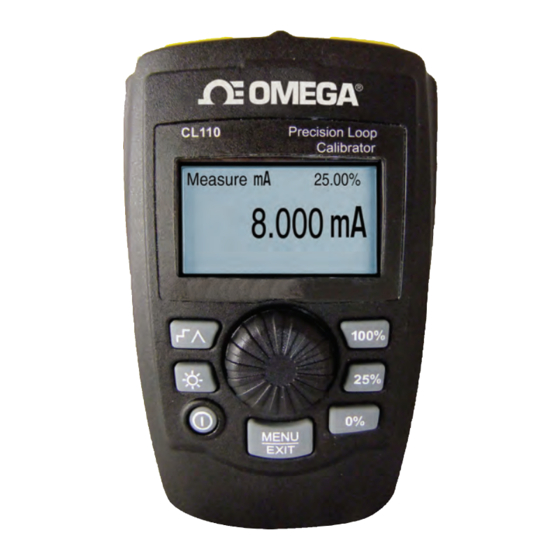
- Page 1 User’s Guide Shop online at omega.com e-mail: info@omega.com For latest product manuals: www.omegamanual.info NORWALK, CT CL110 Precision Loop Calibrator...
- Page 2 Fax: (203) 359-7700 e-mail: info@omega.com For Other Locations Visit omega.com/worldwide The information contained in this document is believed to be correct, but OMEGA accepts no liability for any errors it contains, and reserves the right to alter specifications without notice.
- Page 3 Introduction The OMEGA CL110 mA (loop) calibrator is designed to be simple to use and to offer the highest accuracy of any loop calibrator in it’s class. The calibrator supports the following functions: • Current measurement and sourcing, including selectable 24V supply •...
-
Page 4: Safety Information
1.3 Safety information Symbols Used The following table lists the International Electrical Symbols. Some or all of these symbols may be used on the instrument or in this manual. Symbol Description AC (Alternating Current) AC-DC Battery CE Complies with European Union Directives Double Insulated Electric Shock Fuse... - Page 5 The following definitions apply to the terms “Warning” and “Caution”. • “ Warning” identifies conditions and actions that may pose hazards to the user. • “ Caution” identifies conditions and actions that may damage the instrument being used. Use the calibrator only as specified in this manual, otherwise injury and damage to the calibrator may occur. Warning To avoid possible electric shock or personal injury: • D o not apply more than the rated voltage. See specifications for supported ranges.
- Page 6 • W hen servicing the calibrator, use only specified replacement parts. • T o avoid false readings, which could lead to possible electric shock or personal injury, replace the battery as soon as the battery indicator appears. • T o avoid a violent release of pressure in a pressurized system, shut off the valve and slowly bleed off the pressure before you attach the pressure module to the pressure line. Caution To avoid possible damage to calibrator or to equipment under test: • U se the proper jacks, function, and range for your measurement or sourcing application.
-
Page 7: Calibrator Interface And Operation
2. Calibrator Interface and Operation Simultaneous % Display Precision Loop 4mA = 0.00% Mode Calibrator 20mA = 100.00% Source 0.00% 4.000mA Cursor Step / Ramp Enable 100% Key: Sets Output to 20mA 100% 25% Key: Steps 4, 8, 12, 16, 20mA Backlight On / Off 0% Key: Sets Output to 4mA... -
Page 8: Milliamp Source
2.1 Milliamp Source In the mA Source mode the calibrator outputs a signal from 0 to 24mA into a load of up to 1000 ohms (750 ohms if the internal HART resistor is switched on). Figure 2 shows the main display and typical connections for this mode. -
Page 9: Milliamp Simulate
• P ress MENU/EXIT to enter the main menu described in section 3. • T he text ‘Valve Test’ is shown in the lower center when the valve test function has been enabled on the Setup Menu, section 4.3. Valve test is described in more detail in section 5.2. • T he text ‘250Ω’ text is shown in the lower right corner when the HART resistor has been enabled on the Setup Menu, section 4.4. 2.2 Milliamp Simulate In the mA Simulate mode the calibrator functions like a 2-wire transmitter by controlling the loop current from an external power... -
Page 10: Milliamp Measure Without 24V Power
Automatic step: ∧ Automatic ramp: • P ress MENU/EXIT to enter the main menu described in section 3. • T he text ‘Valve Test’ is shown in the lower center when the valve test function has been enabled on the Setup Menu, section 4.3. Valve test is described in more detail in section 5.2. • T he text ‘250Ω’ text is shown in the lower right corner when the HART resistor has been enabled on the Setup Menu, section 4.4. 2.3 Milliamp Measure without 24V power In the mA Measure mode, the calibrator displays the loop current. -
Page 11: Milliamp Measure With 24V Power
2.4 Milliamp Measure with 24V power In the mA Measure with 24V mode, the calibrator outputs 24VDC while displaying the loop current. The mode is useful for powering a transmitter without the need for a separate power supply. Figure 5 shows the main display and typical connections for this mode. Precision Loop Calibrator Measure 24V... - Page 12 VOLTAGE OUTPUT DEVICE ( – Precision Loop Calibrator Measure 10.000V 100% MENU EXIT Figure 6 3. Main Menu The Main Menu is used to select the primary operating mode of the calibrator or to access the calibrator setup functions. mA Source mA Simulate mA Measure mA Measure with 24V...
-
Page 13: Calibrator Setup Menu
4. Calibrator Setup Menu The calibrator setup menu consists of two screens. The second screen is reached by selecting ‘Other Parameters’ on the first screen. Auto Ramp Time Auto Step Time Valve Test HART 250Ω Resistor Other Parameters mA Span Contrast Auto Shutdown Time Rotate the knob to select an action by moving the reverse video highlight up and down. -
Page 14: Setting Auto Step Time
4.2 Setting Auto Step Time Auto Step Time 10 SEC. Press & hold to Save This function sets the step interval time for the mA Auto Step feature described in more detail in section 5.1. The value can be set from 5 to 300 seconds. -
Page 15: Enabling The Hart Resistor
4.4 Enabling the Hart Resistor HART Resistor Enable This function enables and disables the Hart resistor described in more detail in section 5.3. Rotate the knob to move the reverse video highlight to the desired selection. Press the knob to save the highlighted selection. Press MENU/EXIT to restore the previous selection and return to the main display. -
Page 16: Configuring Auto Shutdown
text modes. Press the knob to save the contrast value. Press MENU/ EXIT to restore the previous selection and return to the main display. 4.7 Configuring Auto Shutdown Auto Shutdown Time 10 MIN. This function sets or disables the time before the unit automatically shuts down if the keypad is not used. -
Page 17: Hart 250Ω Resistor
4. Press the “25%” key to step the output in 25% of span increments, from 0% of span to 100% of span and back. 5.1.2 Automatic Stepping and Ramping 1. Use the main menu to set the calibrator to source or simulate current. -
Page 18: Maintenance
6.1 Replacing Batteries Replace batteries as soon as the battery indicator turns on to avoid false measurement. If the batteries discharge too deeply the CL110 will automatically shut down to avoid battery leakage. Note: Use only AAA size alkaline, lithium batteries, or rechargeable NiMh cells. -
Page 19: Specifications
7. Specifications Functions: mA source, mA simulate, mA read, mA read/ loop power, and volts read. Ranges: mA (0 to 24mA) and Volts (0 to 30VDC) Resolution: 1uA on mA ranges and 1mV on voltage range Accuracy: 0.01% +/- 2LSD all ranges (@23° +/- 5°C) Operating Temp Range: -10°C to 55°C Humidity Range: 10 to 95% non-condensing... - Page 20 Department will issue an Authorized Return (AR) number immediately upon phone or written request. Upon examination by OMEGA, if the unit is found to be defective, it will be repaired or replaced at no charge. OMEGA’s WARRANTY does not apply to defects resulting from any action of the purchaser, including but not limited to mishandling, improper interfacing, operation outside of design limits, improper repair, or unauthorized modification.
- Page 21 Where Do I Find Everything I Need for Process Measurement and Control? OMEGA…Of Course! Shop online at omega.com TEMPERATURE Thermocouple, RTD & Thermistor Probes, Connectors, Panels & Assemblies Wire: Thermocouple, RTD & Thermistor Calibrators & Ice Point References Recorders, Controllers & Process Monitors...
Need help?
Do you have a question about the CL110 and is the answer not in the manual?
Questions and answers