
Related Manuals for Omega PCL1200


Summary of Contents for Omega PCL1200
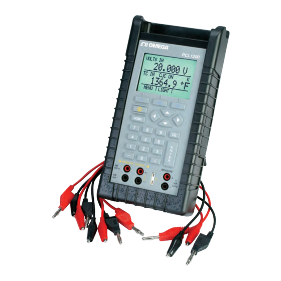
- Page 1 User’s Guide Shop online at omega.com e-mail: info@omega.com For latest product manuals: ww w .omegamanual.info NORWALK, CT PCL1200 Portable, High Accuracy Multifunction Calibrator...
- Page 2 For Other Locations Visit omega.com/worldwide The information contained in this document is believed to be correct, but OMEGA accepts no liability for any errors it contains, and reserves The information contained in this document is believed to be correct, but OMEGA accepts no liability for any errors it contains, and reserves the right to alter specifications without notice.
-
Page 3: Table Of Contents
1. Introduction ..........1.1 Customer Service . -
Page 5: Introduction
1. Introduction The OMEGA PCL1200 Multifunction Process Calibrator is a handheld, battery-operated instrument that measures and sources electrical and physical parameters. The calibrator has the following features and functions: • A dual display. The upper display is used for the measurement of volts, current, and pressure. -
Page 6: Safety Information
1.3 Safety information Symbols Used The following table lists the International Electrical Symbols. Some or all of these symbols may be used on the instrument or in this manual. Symbol Description AC (Alternating Current) AC-DC Battery CE Complies with European Union Directives Double Insulated Electric Shock Fuse... - Page 7 The following definitions apply to the terms “Warning” and “Caution”. • “Warning” identifies conditions and actions that may pose hazards to the user. • “Caution” identifies conditions and actions that may damage the instrument being used. Use the calibrator only as specified in this manual, otherwise injury and damage to the calibrator may occur.
- Page 8 • Disconnect test leads before changing to another measure or source function. • When servicing the calibrator, use only specified replacement parts. • To avoid false readings, which could lead to possible electric shock or personal injury, replace the battery as soon as the battery indicator appears.
-
Page 9: Calibrator Interface
2. Calibrator Interface Figure 1 shows the location of the input and output connections on the calibrator, while Table 1 describes their use. Figure 1. Input/Output Terminals Table 1: Input and Output Terminals Name Description 1, 2 Measure Isolated V, Input terminals for measuring current, voltage, mA terminals and supplying loop power. -
Page 10: Main Display
Figure 2 shows the location of the keys on the calibrator. Table 2 lists the functions of each key. Figure 2. Keypad Table 2. Key Functions Name Function Function Keys F1, Used to operate the menu bar at the bottom of F2, F3 the calibrator display. - Page 11 The display of the calibrator, shown in Figure 3, is divided into three main sections: the upper display, the lower display, and the menu bar. The upper display is used for measuring dc voltage, dc current with and without loop power, and pressure. The lower display can be used for both measuring and sourcing.
- Page 12 2.2 Menu Bar The parameters on the display are controlled by the menu bar, which is located at the bottom of the LCD. The function keys (F1, F2, and F3) are used to navigate through all the levels and choices of the menu bar.
- Page 13 [NEXT] proceeds to the auto off main menu, and [DONE] returns to home menu. Contrast is adjusted using the arrow options, which are available after choosing [CONTRAST]. NOTE: The PCL1200 calibrator offers a wide range contrast adjustment feature to accommodate operation in extreme temperatures.
-
Page 14: Cursor Control / Setpoint Control
[FREQ LEVEL] option is used to adjust the amplitude of the wave. [NEXT] is used to access the contrast main menu, and [DONE] returns to the home menu. When the calibrator is in RTD CUSTOM mode, the RTD custom setup menu, is inserted after the main menu. Options [SET CUSTOM], [NEXT], and [DONE] are available. - Page 15 The three function keys are associated with 0, 25, and 100% values, respectively. 0 and 100% values can be stored by entering a value and then holding down the corresponding function key. The 25% key will then automatically step through the 25% values. Figure 4.
-
Page 16: Using Measure Modes (Lower Display)
3. Using Measure Modes (Lower Display) 3.1 Measuring volts and frequency Electrical parameters volts and frequency can be measured using the lower display. To make the desired measurements, follow these steps: 1. Switch to the lower display [LOWER] from Main Menu. 2. -
Page 17: Measuring Temperature
3.3 Measuring Temperature 3.3-1 Using Thermocouples The calibrator supports the following thermocouple types: B, C, E, J, K, L, N, R, S, T, U, BP , and XK. The characteristics of all the types are described in Specifications section. The calibrator also has a Cold Junction Compensation (CJC) function. -
Page 18: Measuring Pressure
This option can be used along with a table to measure an RTD which is not programmed into the calibrator. 3.4 Measuring Pressure Note: The Omega Pressure Module connector 700mA needs to be purchased to connect pressure module to calibrator. - Page 19 Note: The PCL1200 is compatible with Omega Calibrator Pressure Modules. The accessory PCL-PMA is required for pressure measurement. Note: Pressure is not read from modules with frequency or pulse train mode enabled. Note: On high pressure modules engineering units normally...
-
Page 20: Using Source Modes (Lower Display)
Figure 9. Connections for Measuring Pressure 3.4-1 Zeroing with Absolute Pressure Modules. To zero, adjust the calibrator to read a known pressure, such as barometric pressure. To adjust the calibrator, follow these steps: Enter the pressure zeroing menu. Select [ZERO ]. -
Page 21: Setting 0% And 100% Output Parameters
4.1 Setting 0% and 100% Output Parameters To set the 0% and 100% points, use the following steps: 1. Select the lower display [LOWER] from Main Menu, and choose the desired primary parameter. 2. Select output [OUT] from the input/output control, and enter the desired value. - Page 22 Figure 10. Connections for Sourcing Current 4.3-1 HART Resistor Selection ® The PCL1200 can be set-up so that the 250 ohm resistor required for Hart configuration devices resides inside the PCL1200. Enabling ® the PCL1200's internal 250 ohm resistor eliminates the need to manually add a series resistor during a Hart calibration process.
-
Page 23: Simulating A Transmitter
Figure 10a. 4.4 Simulating a Transmitter To have the calibrator supply a variable test current to a loop in place of a transmitter, follow these steps: 1. Select lower display from the Main Menu. 2. Choose mA simulation from the primary parameters [mA 2W SIM], and enter the desired current. -
Page 24: Sourcing Volts
4.5 Sourcing volts To source volts follow these steps: 1. Select lower display from the Main Menu. 2. Choose [VOLTS] from the primary parameters. Switch to input/ output control and select output [OUT]. 3. Connect the leads for the voltage source terminals, as shown in Figure 12. -
Page 25: Sourcing Thermocouples
a period of 1 second. To source a pulse, use the same connection as for frequency, and proceed as follows: 1. Switch to the lower display and select pulse from the primary parameters. 2. Choose the desired unit and enter the frequency using the keypad. 3. -
Page 26: Sourcing Ohms/Rtds
Figure 14. Connections for Outputting RTDs 4.9 Sourcing Ohms/RTDs To source an RTD, follow these steps: 1. Select lower display from the Main Menu, and choose [RTD] from the primary parameters. 2. Choose output [OUT] from the input/output control, and select RTD type from the sensor types. - Page 27 Note: The calibrator simulates a 2-wire RTD. To connect 3- or 4-wire transmitter, use stacking cables, as shown in Figure 15. 4.9-1 Custom RTD A custom curve-fit PRT may be entered into the calibrator for sourcing and measuring. To do so follow these steps: Switch to lower display.
-
Page 28: Using Isolated Measure Modes
5. Using Isolated Measure Modes (Upper Display) 5.1 Measuring volts and mA Use the following steps to measure the voltage or current output of a transmitter. 1. Select the upper display from the Main Menu. 2. Select the desired primary parameter to be measured. Connect the leads to the isolated inputs of the calibrator, as in Figure 16. -
Page 29: Hart Resistor Selection
® 5.2-1 HART Resistor Selection The PCL1200 can be set-up so that the 250 ohm resistor required for Hart con guration devices resides inside the PCL1200. Enabling the ® PCL1200's internal 250 ohm resistor eliminates the need to manually add a series resistor during a Hart calibration process. - Page 30 To avoid damaging the pressure module from overpressure, never apply pressure above the rated maximum printed on the module. To avoid damaging the pressure module from corrosion, use it only with specified materials. Refer to the pressure module documentation for material compatibility. To measure pressure, follow these steps: 1.
-
Page 31: Using The Upper And The Lower Display For Calibration And Testing
6. Using the Upper and the Lower Display for Calibration and Testing 6.1 Testing an Input or Indicating Device To test and calibrate actuators, recording, and indicating devices using the source functions, follow these steps: 1. Select the lower display and choose the correct primary parameter. -
Page 32: Calibrating A Transmitter
Figure 20. Calibrating an I/P Device 6.3 Calibrating a Transmitter To calibrate a transmitter both the upper and the lower displays will be used; one for measuring and the second a source. This section covers all but the pressure transmitters. A thermocouple temperature transmitter is used in this example. -
Page 33: Calibrating A Pressure Transmitter
Figure 21. Calibrating a Transmitter 6.4 Calibrating a Pressure Transmitter To calibrate a pressure transmitter, use these steps: 1. Select upper display from the Main Menu, and choose current [mA LOOP] from the primary parameters. Return to Main Menu. 2. Select lower display, and choose [PRESSURE] from the primary parameters. -
Page 34: Remote Operation
7. Remote Operation The calibrator can be remotely controlled using a PC terminal, or by a computer program running the calibrator in an automated system. It uses an RS-232 serial port connection for remote operation. With this connection the user can write programs on the PC, with Windows languages like Visual Basic to operate the calibrator, or use ®... -
Page 35: Changing Between Remote And Local Operation
3. For Name enter ASC300. Select the serial port that the unit is connected to. 4. Enter the above information for port settings. 5. Select ASCII setup from File/Properties/Settings and mark these choices: Echo typed characters locally Wrap lines that exceed terminal width 6. - Page 36 Common Commands Standard commands used by most devices. These commands always begin with an "*". For example *IDN? tells the calibrator to return its identification. Query Commands Commands that ask for information. They always end with a "?". For example: FUNC? Returns the current modes of the upper and lower displays.
- Page 37 RTD_TYPE? returns PT385_10 Indefinite ASCII (IAD) Any ASCII characters followed by a terminator. For example: *IDN? returns OMEGA, ASC300, 250, 1.00 7.3-4 Calibrator Status Status registers, enable registers, and queues provide status information on the calibrator. Each status register and queue has a summary bit in the Serial Poll Status Byte.
- Page 38 Service Request Enable Register (SRE) Enables or disables the bits of the STB. Cleared when power is reset. Setting bits to 0 disables them in the STB. Setting the bits to 1 enables them. Bit assignments for the SRE and the STB are shown below.
-
Page 39: Remote Commands And Error Codes
Power On. Set to 1 if power was turned on and off before the Event Status Register was read. Command Error. Set to 1 when the calibrator receives an invalid command. Entering an unsupported RTD type may cause such an error. Execution Error. - Page 40 Table 5: Common Commands Command Description *CLS *CLS (Clear status.) Clears the ESR, the error queue, and the RQS bit in the status byte. Terminates pending Operation Complete commands *ESE Loads a byte into the Event Status Enable register. *ESE? Returns the contents of the Event Status Enable register.
- Page 41 FREQ_LEVEL Sets the frequency and pulse amplitude FREQ_LEVEL? Returns the frequency and pulse amplitude FREQ_TYPE Set the frequency output to continuous (frequency) or pulse. FREQ_TYPE? Returns frequency output type, continuous or pulse FREQ_UNIT Sets the unit for frequency and pulse FREQ_UNIT? Returns the unit for frequency and pulse FUNC?
- Page 42 Table 7: Parameter units Units Meaning milliamps of current Voltage in millivolts Voltage in volts Frequency in cycles per minute Frequency in Hertz Frequency in kiloHertz Ohms Resistance in Ohms Temperature in Celsius Temperature in Fahrenheit Pressure in pounds per square-inch InH2O4C Pressure in inches of water at 4°C InH2O20C...
-
Page 43: Entering Commands
Error Number Error Description The serial input buffer overflowed Too many entries in the command line The serial output buffer overflowed Output is overloaded Calibrator not in pulse train mode when TRIG was received An invalid FREQ_TYPE was received 7.5 Entering Commands Commands for the calibrator may be entered in upper or lower case. - Page 44 *IDN? Returns the manufacturer, model number, and firmware revision of the Calibrator. For example: *IDN? will return OMEGA, PCL1200, 250, 1.00 *OPC Enables the Operation Complete setting in the ESR. This setting makes it possible to check if an operations is complete after it has been initialized.
- Page 45 *SRE? Returns a byte from the SRE. The byte is returned in decimal format. For example: If 40 is returned, bits 5 and 3 are enabled. *STB Returns the status byte in decimal form from the Serial Poll Status Byte. For example;...
- Page 46 CPRT_COEFA This command is used for entering a custom RTD into the calibrator. The numeric value entered after the command will be set as the first coefficient of the polynomial used by the custom RTD. For example: CPRT_COEFA 3.908E-03 enters 3.908e-3 as coefficient A. CPRT_COEFA? Returns the number which was entered for the first coefficient of the polynomial used in the custom RTD.
- Page 47 CPRT_MIN_T Sets the minimum temperature of the custom RTD range. The temperature value must be entered with a degrees label, CEL for Celsius and FAR for Fahrenheit. For example: CPRT_MIN_T -260 CEL enters -260°C as the minimum temperature. CPRT_MIN_T? Returns the value entered for minimum temperature in the range for a custom RTD.
-
Page 48: Freq_Level
FAULT? Returns the error code number of an error that has occurred. The command may be entered when the previous command did not do what it was meant to do. For example, if a value for current output is entered that is bigger than the supported range (0-24mA) FAULT? Would return: 103 which is the code number for an entry over range. -
Page 49: Freq_Unit
FREQ_UNIT Sets the unit for frequency. There are three ranges of frequencies for frequency and pulse modes, CPM (cycles per minute), Hz, and kHz. Use this command to select the right range. For example: FREQ_UNIT HZ sets the frequency to Hz range FREQ_UNIT? Returns the frequency unit currently being used by the frequency and pulse modes. -
Page 50: Out
Returns the model and serial number of the attached pressure unit. Returns NONE if no pressure unit is attached. For example: PRES? Will return OMEGA, 001PNS, 3, 0 PRES_UNIT? Returns the pressure units of both the upper and the lower display. -
Page 51: Remote
REMOTE Puts the calibrator in remote mode. From the remote mode the user can still use the keypad to get back to local unless the command LOCKOUT was entered before REMOTE. Than the keypad is totally locked out, and the user has to send the LOCAL command to get back to local operation. -
Page 52: Tc_Type
SIM? Returns the output of the current simulation. With the example above, the output would be: 5.000000E-03, A TC_TYPE Sets the type of the thermocouple. All available types are shown in the TC Types table in Section 8. (Specifications). For example: TC_TYPE B sets thermocouple type to B TC_TYPE? Returns the type of thermocouple the calibrator is set to. -
Page 53: Tsens_Type
TSENS_TYPE Sets the temperature sensor type to thermocouple, or to RTD for temperature measurement. After the command add TC for thermocouple, or RTD for RTDs. For example: TSENS_TYPE TC sets the sensor type to thermocouple TSENS_TYPE? Returns the type of sensor that is currently set to measure temperature, either TC or RTD. -
Page 54: Speci Cations
8. Specifications All measurements apply at 23°C ± 5°C. unless specified otherwise. Outside of this range the stability of the measurements is ± 0.005%of reading/°C. Table 9: General Specifications Operating Temperature -10°C to 50° Storage Temperature -20°C to 70°C Power 4 X AA batteries;... - Page 55 Table 12: Frequency Measurement/Source Range Accuracy (% of reading ± floor) Read 2.0CPM - 600.0CPM 0.05% ± 0.1CPM 1.0Hz - 1000.0Hz 0.05% ± 0.1Hz 1.00KHz - 10.00KHz 0.05% ± 0.01KHz Source 2.0CPM - 600.0CPM 0.05% 1.0Hz - 1000.0Hz 0.05% 1.00KHz - 10.00KHz 0.250% Input voltage amplitude range on frequency is 1V to 20V zero based square wave only.Output amplitude is adjustable from 1V to 20V, and is a square wave...
- Page 56 Table 16: Thermocouple Read and Source (errors in °C) Range (°C) Accuracy (°C) TC Type Minimum Maximum CJC OFF CJC ON -210.0 -150.0 -150.0 1200.0 -200.0 -100.0 -100.0 600.0 600.0 1000.0 1000.0 1372.0 -250.0 -200.0 -200.0 400.0 -250.0 -200.0 -200.0 -100.0 -100.0 1000.0...
- Page 57 Table 17: RTD Read and Source RTD Type Range (°C) Accuracy Ni120 (672) -80.0 - 260.0 Cu10 -100.0 - 260.0 Cu50 -180.0 - 200.0 Cu100 -180.0 - 200.0 YSI400 15.00 - 50.00 Pt100 (385) -200.0 - 100.0 100.0 - 300.0 300.0 - 600.0 600.0 - 800.0 Pt200 (385)
-
Page 58: Maintenance
Replace batteries as soon as the battery indicator turns on to avoid false measurements. If the batteries discharge too deeply the PCL1200 will automatically shut down to avoid battery leakage. Note: Use only AA size alkaline batteries or optional rechargeable batteries. - Page 59 Department will issue an Authorized Return (AR) number immediately upon phone or written request. Upon examination by OMEGA, if the unit is found to be defective, it will be repaired or replaced at no charge. OMEGA’s WARRANTY does not apply to defects resulting from any action of the purchaser, including but not limited to mishandling, improper interfacing, operation outside of design limits, improper repair, or unauthorized modification.
- Page 60 Where Do I Find Everything I Need for Process Measurement and Control? OMEGA…Of Course! Shop online at omega.com TEMPERATURE Thermocouple, RTD & Thermistor Probes, Connectors, Panels & Assemblies Wire: Thermocouple, RTD & Thermistor Calibrators & Ice Point References Recorders, Controllers & Process Monitors...
Need help?
Do you have a question about the PCL1200 and is the answer not in the manual?
Questions and answers