Ingenico iUP 250 Integration Manual
Hide thumbs
Also See for iUP 250:
- Troubleshooting manual (57 pages) ,
- Quick start and installation manual (2 pages)

Related Manuals for Ingenico iUP 250


Summary of Contents for Ingenico iUP 250
- Page 1 250 & iUR 250 Ingenico – 28-32 Boulevard de Grenelle - 75015 PARIS Tél. 33(0)1 58 01 80 00 - Fax 33 (0)1 58 01 91 35...
- Page 2 Ingenico UNattended products (iUN) such as iUP250 and iUR250, both certified PCI PTS 3.x, or others. It offers all information needed for a successful integration of iUP250 and iUR250 products into unattended kiosk machines. For any sales information please refer to your Ingenico contact into the region. Updates table Version...
-
Page 3: Table Of Contents
Secure management of software ..............39 3.1.3 Operating system ..................40 3.1.4 TELIUM MANAGER ................... 41 3.1.5 Software downloading ................43 3.1.6 Development station ................... 45 iUR250 ......................47 Intégration Guide_iUP250&iUR250 3/83 Copyright © 2012 Ingenico 900009151 R11 000 01/1223 All rights reserved... - Page 4 TERMINAL MANAGEMENT SYSTEM ............... 50 Introduction ..................... 50 Basic functions ....................50 Advanced functions ..................50 Customers savings with Ingenico TMS solution ......... 50 INSTALLATION PROCEDURE IN KIOSKS ............51 Security requirement ..................51 Kiosk mechanical requirements ..............51 General installation recommendations ............51 Kiosk suggested layouts for iUR250 IUP250 ..........
- Page 5 EC standard compliance marking .............. 80 12.5 IC statements ....................81 12.6 Environment (WEEE, Batteries and Packaging) ........83 12.7 Security of your terminal ................83 Intégration Guide_iUP250&iUR250 5/83 Copyright © 2012 Ingenico 900009151 R11 000 01/1223 All rights reserved...
-
Page 6: General
Secure Access Module – the chips storing the electronic cash register in a stored value scheme such as Moneo, Proton or VISA Cash. SubMiniature version A Universal Serial Bus Intégration Guide_iUP250&iUR250 6/83 Copyright © 2012 Ingenico 900009151 R11 000 01/1223 All rights reserved... -
Page 7: Iup250 & Iur250 Payment Solution Presentation
1.2 IUP250 & IUR250 PAYMENT SOLUTION PRESENTATION The iUN series is the new range of Ingenico UNattended (iUN) devices to offer payment into any kiosk through any segments (petrol, transport, vending, parking, etc.). The two first modules offered for contact cards and PIN management are: ... -
Page 8: Diagram Of Iup250 & Iur250 Connectivity And Communications
GSM / GPRS MDB slave (Option) Bluetooth Main Power (Option) MDB master supply (Option) Serial port com2 Card Reader iUR250 Serial port com0 USB device Intégration Guide_iUP250&iUR250 8/83 Copyright © 2012 Ingenico 900009151 R11 000 01/1223 All rights reserved... -
Page 9: Examples Of Integration
1.2.2 Examples of integration Intégration Guide_iUP250&iUR250 9/83 Copyright © 2012 Ingenico 900009151 R11 000 01/1223 All rights reserved... -
Page 10: Services
User licence for M²OS Softwares / Licences Licence for software signature tool, SAT Licence for "EMV Level 2 package " Licence for TCP/IP … Intégration Guide_iUP250&iUR250 10/83 Copyright © 2012 Ingenico 900009151 R11 000 01/1223 All rights reserved... -
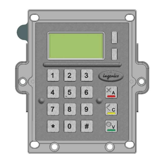
Page 11: Description Of Modules
1.3 DESCRIPTION OF MODULES 1.3.1 iUP250 Front view Rear view Intégration Guide_iUP250&iUR250 11/83 Copyright © 2012 Ingenico 900009151 R11 000 01/1223 All rights reserved... -
Page 12: Technical Hardware Characteristics
Buzzer RGB led internal status indicator 1 Maintenance Button Functionality µSD 2 SAM 1 SIM (optional) 1 Jack for external lighting wake-up mechanism on RS232 connectors Intégration Guide_iUP250&iUR250 12/83 Copyright © 2012 Ingenico 900009151 R11 000 01/1223 All rights reserved... - Page 13 * 55°C is a maximum using temperature for user safety (IEC 60950). The product is operational up to 65°C with no tampering issue. Storage conditions Storage temperature -20°C,+65°C Max relative humidity 85% at 55°C, non-condensing Intégration Guide_iUP250&iUR250 13/83 Copyright © 2012 Ingenico 900009151 R11 000 01/1223 All rights reserved...
-
Page 14: Iup250 Output Connectors Description
1.3.1.2 iUP250 output connectors description COM0 link MDB slave MDB master 2 SAM µSD Pinshield light output COM2 Link Intégration Guide_iUP250&iUR250 14/83 Copyright © 2012 Ingenico 900009151 R11 000 01/1223 All rights reserved... - Page 15 USB hosts USB Device Ethernet Bluetooth Antenna GSM Antenna LLT/Maintenance LED LLT/Maintenance Button Intégration Guide_iUP250&iUR250 15/83 Copyright © 2012 Ingenico 900009151 R11 000 01/1223 All rights reserved...
- Page 16 2 - Wake-up « 0 » => Wake-up « 0 » => Wake-up be compliant. Any devices design to HZ => Stand-by « 0 » => Wake-up Intégration Guide_iUP250&iUR250 16/83 Copyright © 2012 Ingenico 900009151 R11 000 01/1223 All rights reserved...
- Page 17 1.3.1.2.6 COM2 link (optional) The iUP250 PINPad unit can be connected to serial port COM2 if the option is available. The connector type is RJ11. Pin N° Function Wake-up Intégration Guide_iUP250&iUR250 17/83 Copyright © 2012 Ingenico 900009151 R11 000 01/1223 All rights reserved...
- Page 18 EXE power supply. A ferrite Würth ref 74271222 or equivalent must be added with two turns on the cable. Pin N° Function MDBM_RXD ISO_GND MDBM_TXD ISO_GND Intégration Guide_iUP250&iUR250 18/83 Copyright © 2012 Ingenico 900009151 R11 000 01/1223 All rights reserved...
- Page 19 Light off “0” Light on WARNING: This DC Jack is only an output power supply for the Lighting pinshield. Plugin a DC power could damage the iUP250. Intégration Guide_iUP250&iUR250 19/83 Copyright © 2012 Ingenico 900009151 R11 000 01/1223 All rights reserved...
- Page 20 When the iUP250 is ordered with Bluetooth option, it must be connected to an external Bluetooth antenna. Ingenico can provide an antenna, or a standard one can be used. This standard Antenna must have an impedance of 50 Ohm and a maximum gain of 0 dBi.
- Page 21 When the PINPad unit is provided with GPRS functionality (configuration upon request), the external antenna is not provided with the unit. Ingenico can provide an antenna, or a standard one can be used. This standard Antenna must have an impedance of 50 Ohm and a maximum gain of 3.5 dBi.
-
Page 22: Sam & Μsd Installation
After insertion, the cards position is 4 mm out of the products as shown on picture. Cut angle orientation (SIM) 1.3.1.4 Buzzer The buzzer is controlled by application. The frequency depends of software. Intégration Guide_iUP250&iUR250 22/83 Copyright © 2012 Ingenico 900009151 R11 000 01/1223 All rights reserved... -
Page 23: Rgb Backlight
To enter Maintenance mode, press the button at power up or at restart, until the red led starts blinking. To restart the product, press the button until the blue led lights on. Intégration Guide_iUP250&iUR250 23/83 Copyright © 2012 Ingenico 900009151 R11 000 01/1223 All rights reserved... -
Page 24: Cable Protection
Connect the cables, and snap in the part on the rear cover to cover the cables. This sleeve also holds the antenna tool for GPRS and BT options. Cable sealing sleeve clipped on back cover Intégration Guide_iUP250&iUR250 24/83 Copyright © 2012 Ingenico 900009151 R11 000 01/1223 All rights reserved... -
Page 25: Antenna Installation
2. Insert the SMA antenna cable through the slot of the antenna tool. 3. Slide the antenna tool over the SMA Cable connector. 4. Screw the cable. Intégration Guide_iUP250&iUR250 25/83 Copyright © 2012 Ingenico 900009151 R11 000 01/1223 All rights reserved... -
Page 26: Pinpad And Reader Interconnectivity
Connection between the iUP250 and iUR250 is done through USB. Plug the USB cable on iUP250 and iUR250 with a standard USB cable (not provided) or with low profile Ingenico USB cable (spare part reference 29129367) Warning : iUP250 & iUR250 have to be grounded to respect IEC 60950. -
Page 27: Iur250
1.3.2 iUR250 Front view Rear view Intégration Guide_iUP250&iUR250 27/83 Copyright © 2012 Ingenico 900009151 R11 000 01/1223 All rights reserved... -
Page 28: Technical Hardware Characteristics
RGB led indicator Level lock (optional) USB device Link RS232 connection only for wake-up mechanism Storage conditions Storage temperature -20°C,+65°C Max relative humidity 85% at 55°C, non-condensing Intégration Guide_iUP250&iUR250 28/83 Copyright © 2012 Ingenico 900009151 R11 000 01/1223 All rights reserved... -
Page 29: Iur250 Output Connectors Description
1.3.2.2 iUR250 output connectors description USB Device Wake-up connectt Intégration Guide_iUP250&iUR250 29/83 Copyright © 2012 Ingenico 900009151 R11 000 01/1223 All rights reserved... - Page 30 2 - Wake-up « 0 » => Wake-up « 0 » => Wake-up be compliant. Any devices design to HZ => Stand-by « 0 » => Wake-up Intégration Guide_iUP250&iUR250 30/83 Copyright © 2012 Ingenico 900009151 R11 000 01/1223 All rights reserved...
-
Page 31: Rgb Leds
1.3.2.4 iUR250 Optional Lever Lock The Lever lock is controlled by application. It may be used to forbid the withdrawal of the card during chip access. Intégration Guide_iUP250&iUR250 31/83 Copyright © 2012 Ingenico 900009151 R11 000 01/1223 All rights reserved... -
Page 32: Professional Installation Requirement
1.4 PROFESSIONAL INSTALLATION REQUIREMENT Ingenico only sells its products, to qualified partners and integrators. They are in charge of professionally resell, integrate, and install these products inside complete solution for end customers. These end customers solution can be: Petrol station. -
Page 33: Main Accessories
This cable is designed to optimize the required volume for iUR250 & iUP250 installation in the kiosk 2.1.3 iUP250 Power supply Ingenico power supply can be ordered under reference 192017549 (only for 0 to 40°C use) Input: Main voltage supply ranging from 100V to 240V... -
Page 34: Optional Pinshield
Designed specifically for the iUP250, optional privacy shield is compliant with EPC343-08. There are 2 optional privacy shields: standard (no light) and lighting. Standard pinshield Front view Rear view Intégration Guide_iUP250&iUR250 34/83 Copyright © 2012 Ingenico 900009151 R11 000 01/1223 All rights reserved... - Page 35 Lighting pinshield Intégration Guide_iUP250&iUR250 35/83 Copyright © 2012 Ingenico 900009151 R11 000 01/1223 All rights reserved...
- Page 36 Global dimensions 3D design on demand Dimensions of the pinshield Intégration Guide_iUP250&iUR250 36/83 Copyright © 2012 Ingenico 900009151 R11 000 01/1223 All rights reserved...
-
Page 37: Software
The inputs and outputs are managed by interrupts. This provides for simultaneous processing of peripherals, thus increasing system unit performance. It is downloadable to FLASH memory. Intégration Guide_iUP250&iUR250 37/83 Copyright © 2012 Ingenico 900009151 R11 000 01/1223 All rights reserved... -
Page 38: Software Architecture
Application manager UCM component Local Remote Downloading diagno diagnostics stics Applications Transaction USB slave/ Flow PSU 5V Management CB Appli Appli 2 Appli 3 Appli n Intégration Guide_iUP250&iUR250 38/83 Copyright © 2012 Ingenico 900009151 R11 000 01/1223 All rights reserved... -
Page 39: Secure Management Of Software
2. Before running a software, the terminal checks : Its presence by looking for the software’s identity. Its integrity by checking checksums and CRCs. Intégration Guide_iUP250&iUR250 39/83 Copyright © 2012 Ingenico 900009151 R11 000 01/1223 All rights reserved... -
Page 40: Operating System
Inter-application isolation is managed by the Memory Management Unit (MMU). Application download management : The operating system offers the downloading services described in the « Software download » section. Intégration Guide_iUP250&iUR250 40/83 Copyright © 2012 Ingenico 900009151 R11 000 01/1223 All rights reserved... -
Page 41: Telium Manager
Application call time: remote collection, loading, etc. Total number of transactions in each application file contained in system unit. Intégration Guide_iUP250&iUR250 41/83 Copyright © 2012 Ingenico 900009151 R11 000 01/1223 All rights reserved... - Page 42 Diagnostics by USB key Diagnostic files are copied to a USB key if present at start-up. Intégration Guide_iUP250&iUR250 42/83 Copyright © 2012 Ingenico 900009151 R11 000 01/1223 All rights reserved...
-
Page 43: Software Downloading
The LLT is formed by: A PC running with Windows Seven, Vista Pro, XP, 2003 Server, 2000 Professional SP2 A INGENICO loading software, A PC-terminal connecting cable Local loading is performed: From a PC equipped with the Local Loading Tool (LLT) on the COM serial or slave USB link ... - Page 44 The downloaded software is run in a secure context by authenticity check. Intégration Guide_iUP250&iUR250 44/83 Copyright © 2012 Ingenico 900009151 R11 000 01/1223 All rights reserved...
-
Page 45: Development Station
The software is written in high level C language in a multi-application environment. Ingenico provides the complete set of software and the equipment required for development. This also includes the documentations. Training sessions can also be proposed. - Page 46 This includes the hot line, and updates to the documentations and softwares during this period. Software package A set of software packages, used to simplify development of applications (EMV level 2, contactless…) is available. Intégration Guide_iUP250&iUR250 46/83 Copyright © 2012 Ingenico 900009151 R11 000 01/1223 All rights reserved...
-
Page 47: Iur250
/ output handling, simultaneous management of all the peripherals is ensured, enhancing PINPad performance. Data can be loaded in the internal flash memory of the processor. Intégration Guide_iUP250&iUR250 47/83 Copyright © 2012 Ingenico 900009151 R11 000 01/1223 All rights reserved... -
Page 48: Software Architecture
RSA algorithm with 2048 bits key size. Intégration Guide_iUP250&iUR250 48/83 Copyright © 2012 Ingenico 900009151 R11 000 01/1223 All rights reserved... -
Page 49: Operating System
They can be used later by the maintenance subsystem during remote or local diagnostics. Tamper proof Application / System management: the operating system offers the devices described in the data security section. Intégration Guide_iUP250&iUR250 49/83 Copyright © 2012 Ingenico 900009151 R11 000 01/1223 All rights reserved... -
Page 50: Terminal Management System
4 TERMINAL MANAGEMENT SYSTEM 4.1 INTRODUCTION Ingenico developed its own Terminal Estate Management System called IngEstate. It is a link between an organisation with an estate of payment terminals and their merchants. It allows users to remotely manage payment terminals, modify their software content and interact with merchants. -
Page 51: Installation Procedure In Kiosks
(according to PCI PTS - Modular Derived Test Requirements Version 3.1 October 2011). If the unattended device doesn’t provide such protection, an Ingenico privacy shield option can be provided. iUP250 and iUR250 must be mounted on the unattended machine as indicated in the installation guide to activate removal detector. -
Page 52: Vertical Pinpad Above The Reader
5.4.1 Vertical PINPad above the reader This is the most common layout and simplest installation. Minimum distance between reader and PINPad is 23 mm. 23 mm Intégration Guide_iUP250&iUR250 52/83 Copyright © 2012 Ingenico 900009151 R11 000 01/1223 All rights reserved... -
Page 53: Leaned Backward Pinpad Above Vertical Reader
This installation provides a good ergonomic integration. Maximum leaning of the keypad is 30 degrees. Minimum distance between reader and PINPad is 25mm for cable access. Intégration Guide_iUP250&iUR250 53/83 Copyright © 2012 Ingenico 900009151 R11 000 01/1223 All rights reserved... -
Page 54: Leaned Forward Reader Above Leaned Backward Pinpad
The reader must be Horizontal or 45° max leaned in order to evacuate liquids by the front. Maximum backward leaning of the keypad is 30 degrees. Intégration Guide_iUP250&iUR250 54/83 Copyright © 2012 Ingenico 900009151 R11 000 01/1223 All rights reserved... -
Page 55: Optional Pinshield Layout Considerations
A large air intake must be provided in the kiosk. It is also recommended to have the kiosk in overpressure to avoid dust. Intégration Guide_iUP250&iUR250 55/83 Copyright © 2012 Ingenico 900009151 R11 000 01/1223 All rights reserved... -
Page 56: Kiosk Grounding Consideration
5.7 KIOSK GROUNDING CONSIDERATION All parts of the kiosk should be connected to the ground using ground cables. Connect to Ground Intégration Guide_iUP250&iUR250 56/83 Copyright © 2012 Ingenico 900009151 R11 000 01/1223 All rights reserved... -
Page 57: Assembly Procedure For Iur250 Card Reader
The iUR250 requires a minimum volume inside the kiosk. It is detailed in the drawing below. 3D design on demand. The minimum volume is 108 mm width x 73 mm height x 146 mm deep. Picture of iUR250 minimum volume Intégration Guide_iUP250&iUR250 57/83 Copyright © 2012 Ingenico 900009151 R11 000 01/1223 All rights reserved... -
Page 58: Kiosk Preparation For Iur250 Installation
Fixing must be done by 4 M4 to M6 x12mm welded studs. iUR250 footprint area iUR250 Anti-removal switches area Cut-out drawing for iUR250. 3D design on demand. Intégration Guide_iUP250&iUR250 58/83 Copyright © 2012 Ingenico 900009151 R11 000 01/1223 All rights reserved... -
Page 59: Installing The Reader Iur250
Screw the 4 nuts with a 1.0-1.3 N.m torque. It is recommended to use threadlocker fluid to prevent unscrewing with vibrations. Picture showing the installation of the iUR250 Intégration Guide_iUP250&iUR250 59/83 Copyright © 2012 Ingenico 900009151 R11 000 01/1223 All rights reserved... -
Page 60: Water Evacuation Consideration
The pipe is provided with the product and has to be sticked to the evacuation hole. Evacuation pipe Picture showing evacuation pipe Intégration Guide_iUP250&iUR250 60/83 Copyright © 2012 Ingenico 900009151 R11 000 01/1223 All rights reserved... -
Page 61: Connecting The Iur250 To The Kiosk Ground
The iUR250 should be connected to the ground of kiosk chassis using a copper braid fastened with the provided grounding screw and washer. Grounding screw Grounding hole Picture showing the grounding ground hole and screw of the iUR250 Intégration Guide_iUP250&iUR250 61/83 Copyright © 2012 Ingenico 900009151 R11 000 01/1223 All rights reserved... -
Page 62: Assembly Procedure For Iup250 Pinpad
3D design on demand. The minimum volume is 123mm width x 154 mm height x 52 mm depth Picture showing the minimum volume for the iUR250 Intégration Guide_iUP250&iUR250 62/83 Copyright © 2012 Ingenico 900009151 R11 000 01/1223 All rights reserved... -
Page 63: Kiosk Preparation For Iup250 New Installation
3D step files are also available upon request. Fixing must be done by 6 M4x16mm welded studs. Drawing of the cut-out for the iUP250 3D design on demand. Intégration Guide_iUP250&iUR250 63/83 Copyright © 2012 Ingenico 900009151 R11 000 01/1223 All rights reserved... -
Page 64: Installing The Iup250 Pinpad In New Kiosk
Screw the 6 nuts with a 1.0 N.m torque. It is recommended to use threadlocker fluid to prevent unscrewing with vibrations. Picture showing a new installation of the iUP250 Intégration Guide_iUP250&iUR250 64/83 Copyright © 2012 Ingenico 900009151 R11 000 01/1223 All rights reserved... -
Page 65: Kiosk Preparation For Iup250 Installation As Replacement Of I9530 Product
AS REPLACEMENT OF I9530 PRODUCT The installation of iUP250 as replacement of i9530 product requires an adapting sheet metal part. This part is not provided by Ingenico. It is required by security regulation that this part must be permanently mounted on the kiosk (i.e by soldering) and cannot be removed from the kiosk. -
Page 66: Installing The Iup250 Pinpad As Replacement Of I9530
Top studs need to be cut to 11 mm to avoid interference with the cable sleeve. Picture showing the installation of the iUP250 in existing i9530 kiosk Intégration Guide_iUP250&iUR250 66/83 Copyright © 2012 Ingenico 900009151 R11 000 01/1223 All rights reserved... -
Page 67: Connecting The Iup250 To The Kiosk Ground
2 grounding studs and connect this braid to the chassis. Ground studs to connect copper braid to ground. Picture showing the grounding of the iUP250 Intégration Guide_iUP250&iUR250 67/83 Copyright © 2012 Ingenico 900009151 R11 000 01/1223 All rights reserved... -
Page 68: Installing The Optional Pinshield
A diameter 10 additional hole is required for the Lighting pinshield to pass the cable through the kiosk. Picture showing the cut-out and holes for the iUP250 pinshield Intégration Guide_iUP250&iUR250 68/83 Copyright © 2012 Ingenico 900009151 R11 000 01/1223 All rights reserved... -
Page 69: Installing The Standard Pinshield
Wedge thickness 2.5 3 mm Wedge thickness 3.5 4 mm Wedge thickness 4.5 5 mm Wedge thickness 5.5 Wedge Picture showing installation of the iUP250 standard pinshield. Intégration Guide_iUP250&iUR250 69/83 Copyright © 2012 Ingenico 900009151 R11 000 01/1223 All rights reserved... -
Page 70: Installing The Lighting Pinshield
Wedge thickness 3.5 4 mm Wedge thickness 4.5 5 mm Wedge thickness 5.5 Wedge Light module with cable Picture showing installation of the iUP250 lighting pinshield. Intégration Guide_iUP250&iUR250 70/83 Copyright © 2012 Ingenico 900009151 R11 000 01/1223 All rights reserved... -
Page 71: Informations On Iuc150 Or Iuc180 Contacless Unattended Modules
For the grounding connection both studs must be connected to get the best ESD performance. The kiosk panel thickness must be between 2 mm and 5 mm. The iUC150 or iUC180 use EVA (European vending association) mounting standard. Intégration Guide_iUP250&iUR250 71/83 Copyright © 2012 Ingenico 900009151 R11 000 01/1223 All rights reserved... -
Page 72: Maintenance
Ingenico). This operation can be performed using the LLT or a USB key (see § Loading by USB key) For more information concerning configuration, contact Ingenico Technical Support. 9.2 PRODUCTS COMMISIONNING Please refer to ICO/ETU/11/1849/YM : Commissioning User's Guide. To be able to perform the commissioning procedure the anti-removal must be correctly mounted see chapter 6.2 for iUR250 and 7.2 for iUP250. -
Page 73: Reactivation
The reactivation process can be achieved with a tool terminal and two smart cards with pin codes. (For more information, contact commercial department of Ingenico) On the iUR250 if reactivation process fails, check that the application has been re- charged and re-attempt. -
Page 74: Cleaning Instructions
Do not put anything into the slot of the smart card reader It is recommended to clean regularly the hybrid reader smart connector with dry cleaning cards. Intégration Guide_iUP250&iUR250 74/83 Copyright © 2012 Ingenico 900009151 R11 000 01/1223 All rights reserved... -
Page 75: Disassembling The Products According To Weee Directive
Ce document est destiné aux installations de traitement et de recyclage. Il fournit les instructions de base pour le démontage de produits Ingenico afin de retirer les composants et matériaux nécessitant un traitement sélectif, tel que défini par la directive européenne 2002/96/CE, sur les Déchets d’Equipements Electriques et Electroniques (DEEE). - Page 76 Oter les 6 écrous maintenant l’entretoise plastique. Oter l’entretoise plastique, puis la tôle arrière, puis le support plastique de Remove the keypad card. Oter la carte clavier Remove the battery from the keypad printed circuit board Oter la pile rechargeable de la carte clavier. Intégration Guide_iUP250&iUR250 76/83 Copyright © 2012 Ingenico 900009151 R11 000 01/1223 All rights reserved...
-
Page 77: Iur250 End-Of-Life Disassembly Instructions
Ce document est destiné aux installations de traitement et de recyclage. Il fournit les instructions de base pour le démontage de produits Ingenico afin de retirer les composants et matériaux nécessitant un traitement sélectif, tel que défini par la directive européenne 2002/96/CE, sur les Déchets d’Equipements Electriques et Electroniques (DEEE). - Page 78 Unclip, and remove the dome support and the water collector Déclipser et retirer le Support dôme et le réceptacle eau Remove the battery from the main circuit board Retirer la pile du circuit imprimé principal Intégration Guide_iUP250&iUR250 78/83 Copyright © 2012 Ingenico 900009151 R11 000 01/1223 All rights reserved...
-
Page 79: Standards
12.2 TEMPERATURE AND HUMIDITY Operating & Storage conditions : o Relative humidity: 5% to 85% non-condensing. o External temperature range: -20 °C to 65 °C. Intégration Guide_iUP250&iUR250 79/83 Copyright © 2012 Ingenico 900009151 R11 000 01/1223 All rights reserved... -
Page 80: Environmental Specification Continued
- Limits and measurement methods. EN 55022 2006 + A1 (2007) EN 55024: Data processing equipment – Immunity characteristics - Limits and measurement methods. Issue 1998 + A1- 2001 + A2 – 2003 Intégration Guide_iUP250&iUR250 80/83 Copyright © 2012 Ingenico 900009151 R11 000 01/1223 All rights reserved... -
Page 81: Ic Statements
Les types d'antenne non inclus dans cette liste, ou dont le gain est supérieur au gain maximal indiqué, sont strictement interdits pour l'exploitation de l'émetteur. Intégration Guide_iUP250&iUR250 81/83 Copyright © 2012 Ingenico 900009151 R11 000 01/1223 All rights reserved... - Page 82 This device must be installed to provide a separation distance of at least 20cm from all persons and must not be co-located or operating in conjunction with any other antenna or transmitter. Intégration Guide_iUP250&iUR250 82/83 Copyright © 2012 Ingenico 900009151 R11 000 01/1223 All rights reserved...
-
Page 83: Environment (Weee, Batteries And Packaging)
The associated symbol means that WEEE and waste batteries must not be thrown away but collected separately and recycled. Ingenico ensures that efficient collection and recycling schemes are set-up for WEEE and batteries according to the local regulation of your country. Please contact your retailers for more detailed information about the compliance solution in place for disposing of your old product and used batteries.
Need help?
Do you have a question about the iUP 250 and is the answer not in the manual?
Questions and answers