Sign In
Upload
Download
Table of Contents
Contents
Add to my manuals
Delete from my manuals
Share
URL of this page:
HTML Link:
Bookmark this page
Add
Manual will be automatically added to "My Manuals"
Print this page
×
Bookmark added
×
Added to my manuals
Manuals
Brands
Ingenico Manuals
Payment Terminal
iUC150
Integration manual
Ingenico iUC150 Integration Manual
Contactless payment
Hide thumbs
1
2
Table Of Contents
3
4
5
6
7
8
9
10
11
12
13
14
15
16
17
18
19
20
21
22
23
24
25
26
27
28
29
30
31
32
33
34
35
36
37
38
39
40
41
42
43
44
45
46
47
48
49
50
51
52
53
54
55
56
57
58
59
60
61
62
63
64
65
66
67
68
69
70
page
of
70
Go
/
70
Contents
Table of Contents
Bookmarks
Table of Contents
Table of Contents
1 General
Definition of Acronyms
Iuc150 & Iuc180 Payment Solution Presentation
Diagram of Iuc180 & Iuc150 Connectivity and Communications
Services
Description of Modules
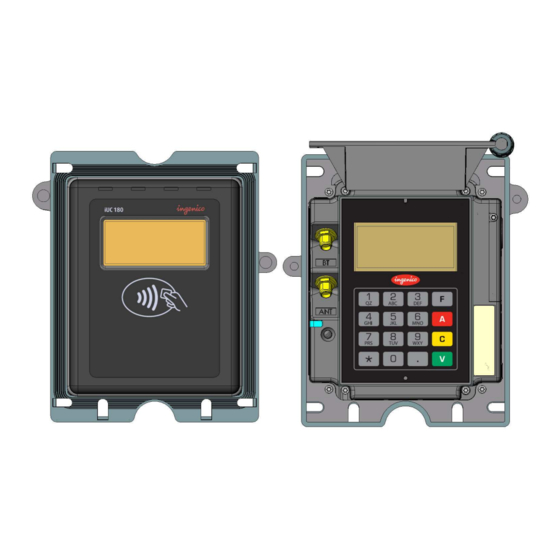
Iuc180
Technical Hardware Characteristics
Iuc180 Output Connectors Description
SAM & Μsd Installation
Buzzer
RGB Backlight
Contactless Leds & Contactless Logo
Maintenance Button and LED
Keypad
Cable Protection
Antenna Installation
Grounding Connections
Appearance Personalisation
Iuc150
Technical Hardware Characteristics
Iuc150 Output Connectors Description
SAM Installation
Buzzer
Contactless Leds & Contactless Logo
Cable Protection
Grounding Connections
Appearance Personalisation
Contactless Reader Iuc150 and I9500 Interconnectivity
Professional Installation Requirement
2 Main Accessories
Generality
Optional USB Cable
Iuc150 Power Supply
Serial Cable
Adapter Cable
LLT Cable
Stand-By Management Cable
3 Iuc180/Iuc150 Software
Software Architecture
Secure Management of Software
Operating System
TELIUM MANAGER on Iuc180 Only
Software Downloading
Development Station (Iuc180)
4 Terminal Management System (Iuc180)
Introduction
Basic Functions
Advanced Functions
Customers Savings with Ingenico TMS Solution
5 Installation Procedure in Kiosks
Kiosk Mechanical Requirements
General Installation Recommendations
Kiosk Suggested Layouts for Iuc150 Iur250 IUP250
6 Assembly Procedure for Iuc180 and Iuc150
Kiosk Minimum Volume for Iuc180
Kiosk Minimum Volume for Iuc150
Kiosk Preparation for Iuc150 or 180 New Installation
Installing the Iuc150/Iuc180 in New Kiosk
Connecting the Iuc180 or 150 to the Kiosk Ground
Kiosk Mechanical Requirements
7 Maintenance
Configuration
Operating Life
8 Cleaning Instructions
9 Disassembling the Products According to Weee Directive
Iuc180 End-Of-Life Disassembly Instructions
IUC150 End-Of-Life Disassembly Instructions
10 Standards
Iuc 150 Electrical Consumptions
Iuc 180 Electrical Consumptions
Temperature and Humidity
Environmental Specification Continued
EC Standard Compliance Marking
IC Statements
FCC Statement
Environment (WEEE, Batteries and Packaging)
Advertisement
Quick Links
1
Diagram of Iuc180 & Iuc150 Connectivity and Communications
2
Technical Hardware Characteristics
3
Configuration
Download this manual
Contactless payment
iUC150 & iUC180
Ingenico – 28-32 Boulevard de Grenelle - 75015 PARIS
Tél. 33(0)1 58 01 80 00 - Fax 33 (0)1 58 01 91 35
Table of
Contents
Previous
Page
Next
Page
1
2
3
4
5
Advertisement
Table of Contents
Need help?
Do you have a question about the iUC150 and is the answer not in the manual?
Ask a question
Questions and answers
Related Manuals for Ingenico iUC150
Payment Terminal Ingenico iUP 250 Integration Manual
(83 pages)
Payment Terminal Ingenico iPP320 Troubleshooting Manual
Telium guide (57 pages)
Payment Terminal Ingenico iUP250 Quick Start And Installation Manual
(2 pages)
Payment Terminal Ingenico iSelf Series Integration Manual
Worldline six payment services (23 pages)
Payment Terminal Ingenico iUC280 Owner's Manual
Compact multiple reader (10 pages)
Payment Terminal Ingenico iUC250 Owner's Manual
Compact multiple reader (10 pages)
Payment Terminal Ingenico iUC285 Owner's Manual
Compact multiple reader (10 pages)
Payment Terminal Ingenico iUC180 Integration Manual
Contactless payment (70 pages)
Payment Terminal Ingenico IUC150B Quick Start And Installation Manual
(13 pages)
Payment Terminal Ingenico iUP250LE Integration Manual
Worldline six payment services (23 pages)
Payment Terminal Ingenico ICT220 User Manual
(17 pages)
Payment Terminal Ingenico ICT250 Quick Reference Manual
(15 pages)
Payment Terminal Ingenico ICT-250 Home Working Manual
(8 pages)
Payment Terminal Ingenico iCT250 Setup Manual
By elavon talech (9 pages)
Payment Terminal Ingenico iWL220 Manual
(19 pages)
Payment Terminal Ingenico iSMP-Companion User Manual
(24 pages)
This manual is also suitable for:
Iuc180
Table of Contents
Print
Rename the bookmark
Delete bookmark?
Delete from my manuals?
Login
Sign In
OR
Sign in with Facebook
Sign in with Google
Upload manual
Upload from disk
Upload from URL


Need help?
Do you have a question about the iUC150 and is the answer not in the manual?
Questions and answers